Article

Printing Cu on a Cold-Sprayed Cu Plate via Selective Laser Melting—Hybrid Additive Manufacturing

1
College of Mechanical Engineering, Yangzhou University, Yangzhou 225127, China
2
Materials Technology, Helmut-Schmidt-University/University of the Federal Armed Forces Hamburg, 22043 Hamburg, Germany
3
The Key Lab of Guangdong for Modern Surface Engineering Technology, National Engineering Laboratory for Modern Materials Surface Engineering Technology, Institute of New Materials, Guangdong Academy of Sciences, Guangzhou 510651, China
4
Department of Mechanical, Manufacturing and Biomedical Engineering, Trinity College Dublin, The University of Dublin, Parsons Building, D02 PN40 Dublin, Ireland
5
Department of “Engineering of Control Systems, Materials and Technologies in Mechanical Engineering”, Kuban State Technological University, Moskovskaya Street 2, 350072 Krasnodar, Russia
*
Authors to whom correspondence should be addressed.
J. Manuf. Mater. Process. 2023, 7(6), 188; https://doi.org/10.3390/jmmp7060188
Submission received: 6 September 2023 / Revised: 28 September 2023 / Accepted: 18 October 2023 / Published: 24 October 2023
(This article belongs to the Special Issue Hybrid Manufacturing)

Abstract

:
The development of the additive manufacturing (AM) technology proffers challenging requirements for forming accuracy and efficiency. In this paper, a hybrid additive manufacturing technology combining fusion-based selective laser melting (SLM) and solid-state cold spraying (CS) was proposed in order to enable the fast production of near-net-shape metal parts. The idea is to fabricate a bulk deposit with a rough contour first via the “fast” CS process and then add fine structures and complex features through “slow” SLM. The experimental results show that it is feasible to deposit an SLM part onto a CS part with good interfacial bonding. However, the CS parts must be subject to heat treatment to improve their cohesion strength before being sending for SLM processing. Otherwise, the high tensile residual stress generated during the SLM process will cause fractures and cracks in the CS part. After heat treatment, pure copper deposited by CS undergoes grain growth and recrystallization, resulting in improved cohesive strength and the release of the residual stress in the CS parts. The tensile test on the SLM/CS interfacial region indicates that the bonding strength increased by 38% from 45 ± 7 MPa to 62 ± 1 MPa after the CS part is subject to heat treatment, and the SLM/CS interfacial bonding strength is higher than the CS parts. This study demonstrates that the proposed hybrid AM process is feasible and promising for manufacturing free-standing SLM-CS components.

1. Introduction

Selective Laser Melting (SLM) is an additive manufacturing (AM) process where a high-power laser is applied to selectively melt metallic powders layer by layer and eventually build a near-net-shape component. It offers the ability to rapidly produce a component having complex geometry with fine details, allowing for the customization of products at an acceptable cost, giving no material waste through recycling unprocessed powder. It is hence well recognized as the technology of future industry. SLM is a promising technology for producing metal parts with excellent mechanical properties, including high-density pure copper and other metals. Several investigations and developments have focused on optimizing laser parameters, scanning strategies and post-processing to achieve the desired results [1,2,3,4,5]. Adjusting laser parameters such as power, wavelength, spot size, and scanning speed is crucial for achieving the desired results in SLM. Optimizing these parameters can lead to better control over the melting and solidification of the metal powder, resulting in parts with improved mechanical properties. The way the laser scans and fuses the metal powder layers can significantly impact the quality of the final part. Various scanning strategies, such as hatch patterns, layer thickness, and laser path planning, can be optimized to reduce defects and ensure high-density parts. The choice of metal powder is critical. Pure copper is a material that can be challenging to work with due to its high thermal conductivity. However, with the right processing parameters and strategies, it is possible to achieve high-density parts with good mechanical properties. Post-processing steps, such as heat treatment and stress relief, can further enhance the mechanical properties of SLM-produced metal parts. These steps can help reduce residual stresses and improve the overall part quality. Implementing quality control measures during and after the SLM process is essential to ensure that the final parts meet the desired standards. Non-destructive testing methods, such as CT scanning, can be used to identify and address defects. Ongoing research and development in the field of SLM are essential to continually improve the process and push the boundaries of what is achievable in terms of material selection, part complexity, and mechanical properties. SLM is a rapidly evolving technology, and as advancements in laser technology, materials, and process control continue, it is becoming increasingly feasible to produce high-density, high-quality metal parts, including pure copper and other metals, for a wide range of applications. These developments have the potential to revolutionize industries such as aerospace, automotive, and medical devices, where high-performance metal components are essential.
Some studies [6,7,8] are focused on the microstructure evolution, formation of defects such as cracks, differences in mechanical properties, process parameters and methods of various alloy materials such as Inconel 718, Al-Si-10Mg, and Ti-6Al-4V during additive manufacturing. The studies involve experiments, analysis, and simulations to explore how these factors interact and influence the final product. These works can contribute to the advancement of SLM processes, optimal process window, and quality optimization. Due to the high cooling rate and fast solidification during the manufacturing process, SLM 316L stainless steel typically has a fine grain structure, thus having higher yield strength, tensile strength, and hardness as compared to forged and casted stainless steel [9]. With heat treatment, such fine grains of SLM 316L stainless steel grow into coarse grain, resulting in a significant decrease in strength and an increase in ductility [10,11]. Guo et al. [12] prepared Ti6Al4V-x Cu alloy using Ti6Al4V and Cu powder through SLM. The microstructure, corrosion resistance, antibacterial performance, and cell compatibility of Ti6Al4V-x Cu alloy were analyzed, which has important value in practical applications in orthopedics and dentistry. However, since a laser is required to locally melt powder over a very small area point by point and then layer by layer, the deposition rate of SLM process is rather low, which results in long manufacturing time, especially when making large components. This significantly limits the application of SLM technology in a broader field. Also, the printing efficiency of SLM process is relatively low. The processing speed of SLM is highly dependent on many factors, including processing powder materials, machine brands and models, processing parameters, and the complexity of the object to be printed. Generally, a deposition rate between 0.4 kg/h and 5.0 kg/h can be achieved for SLM [13,14,15].
Cold spray (CS) is an emerging solid particle deposition and AM technology [16,17,18]. Feedstock powders are accelerated by a supersonic gas passing through a de-Laval nozzle and subsequently impacting onto a substrate to form a coating or bulk structure. CS feedstock can be deposited onto various substrates without experiencing melting; therefore, defects associated with other fusion-based AM processes can be avoided in CS. Due to the deformation-induced dynamic recrystallization, the grains of CS 316L stainless steel are refined during deposition. Most importantly, the material deposition rate of CS is much faster than that of SLM [18]. For CS, the deposition rate of materials such as Al and Cu can easily reach dozens of kilograms per hour [19], which is far higher than that in SLM processes. However, due to the lack of manufacturing precision, CS products typically have a near net shape but with simple geometry and a rough surface in their as-fabricated state [17].
As discussed above and is also well addressed in the literature, SLM and CS each have unique advantages and drawbacks. The fusion-based SLM process excels in the production of complex parts which requires high spatial resolution but not in a time efficient manner, while the solid-state CS process builds component rapidly but lacks manufacturing accuracy [18]. Considering these, in 2018, Yin et al. have proposed a ‘hybrid additive manufacturing’ concept that combines SLM and CS to take the benefits of each process to realize fast and high-precision fabrication [17]. As preliminary studies, they successfully cold-sprayed metal materials onto substrates made by SLM and studied the CS/SLM interfacial microstructures, which is not difficult to implement. However, CS materials onto an SLM substrate may not be frequently encountered in practical engineering applications. A more realistic manufacturing route for the “hybrid” is to fabricate a bulk deposit with a rough contour first via CS and then add fine structures and complex features through SLM. Therefore, in this paper, in order to prove the feasibility of the aforementioned hybrid SLM/CS concept, we selected Cu as an exemplar material, used CS to make bulk Cu substrates, and then added fine features on the CS substrates via SLM. Following fabrication, the microstructures at the SLM/CS interfaces of the hybrid parts and bonding strength at the interface were also investigated.

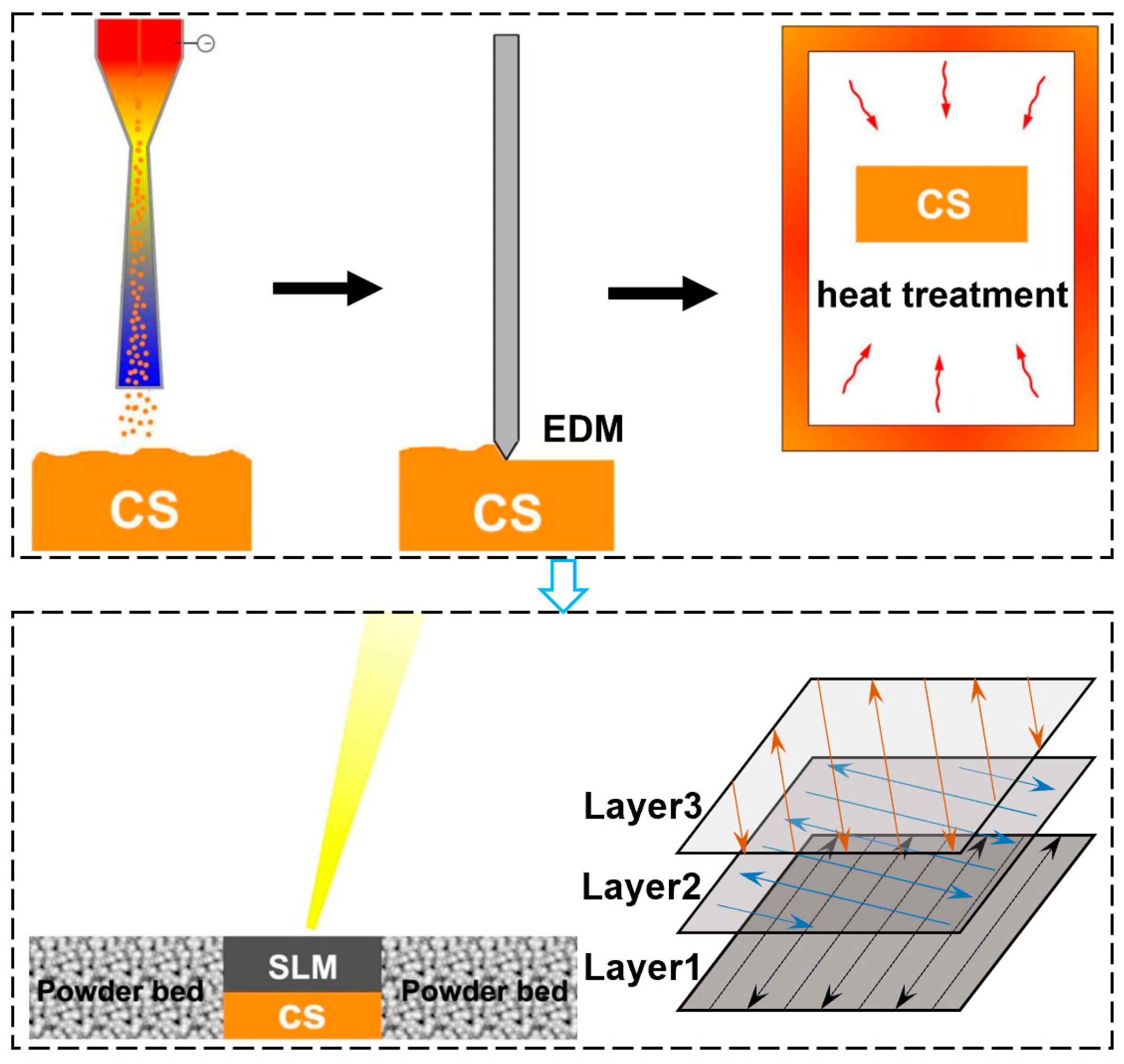
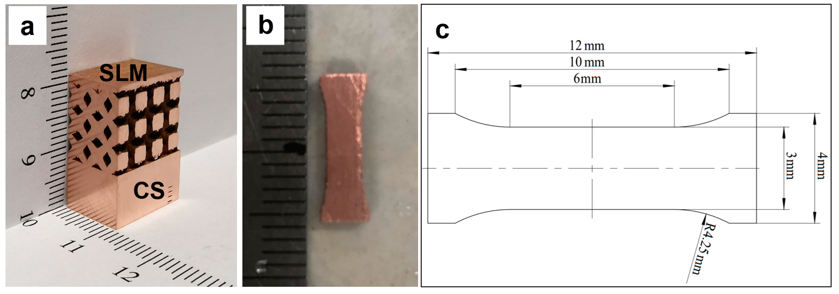
2. Material and Methods

Figure 1 shows the schematic of the hybrid AM process. CS processes were conducted on a commercial CS system (PCS-1000, Plasma Giken, Japan) to fabricate thick plates for the following SLM processing. During the manufacturing process, the CS nozzle trajectory followed the standard zigzag pattern. Nitrogen is used as a propulsion gas. The SLM process was conducted on a commercial SLM machine (EOS M290, Germany) under a high-purity argon environment (Oxygen content below 1%). The Cu plates made from the previous CS processes were flattened via electrical discharge machining (EDM) and then used as the substrates for the SLM part fabrication. The substrates were preheated to 80 °C before spreading powders. Laser scans were applied in a zigzag pattern with an angle of 67° between adjacent layers. Detailed CS and SLM processing parameters are provided in Table 1.
Spherical Cu powders (Beijing COMPO Advanced Technology, Beijing, China) were used as raw materials for the fabrication of hybrid AM samples. The particle size range is 15~53 µm. The morphology of Cu powders is shown in Figure 2. In addition, for studying how the heat treatment of the CS part influences the SLM/CS interfacial microstructure and bonding, a CS Cu substrate was subject to heat treatment at 500 °C for 4 h with a heating rate of 10 °C/min before SLM processing. Based on the authors previous study [20], the cohesion strength of CS Cu could be significantly improved by the chosen of the heat treatment parameters. Figure 3a shows the photo of the Cu parts made via the hybrid AM process.
Figure 3a shows the as-fabricated part made with the hybrid AM process. A network structure is deposited on the CS block, with the black color as the empty part. Following fabrication, the microstructure of the hybrid AM parts was studied using an OM (optical microscope, Leica, Germany) and SEM (Carl Zeiss ULTRA, Germany). All samples were polished using standard metallographic procedures with the final polishing step applied using 0.06 μm colloidal silica solution. The polished Cu samples were etched with a regent of 5 g FeCl3, 10 mL HCl and 100 mL water. The porosity of CS and SLM components was measured using binary image analysis with open-source image analysis software (ImageJ). The cross-sectional image was converted to binary format, and then porosity was calculated as the area ratio between the black pores and the white surface background. The porosity of each sample was considered as the average of three randomly selected micrographs in each sample cross-section. Struers DuraScan 70 was used to perform Vickers microhardness measurements in the cross-section using a load of 200 g (HV 0.2) and distance between indentations of 0.2 mm. In order to measure the interfacial bonding strength between the SLM and CS parts, non-standard dog-bone-shaped tensile samples with a length of 12 mm, a gauge length of 6 mm, a width of 3 mm, and a thickness of 3 mm were extracted from the SLM/CS interfacial region with the interface located exactly in the middle of the tensile samples as shown in Figure 3b,c. The tensile samples were tested on Instron 5982 at a cross-head displacement rate of 0.2 mm/min.

3. Results and Discussion

To analyze the feasibility of the hybrid AM method for the SLM Cu deposited on the CS Cu, we conducted a comparative study on two types of mixed additive manufacturing samples with and without heat treatment. The microstructure, hardness, and bonding strength of the sample under the two conditions were discussed separately.

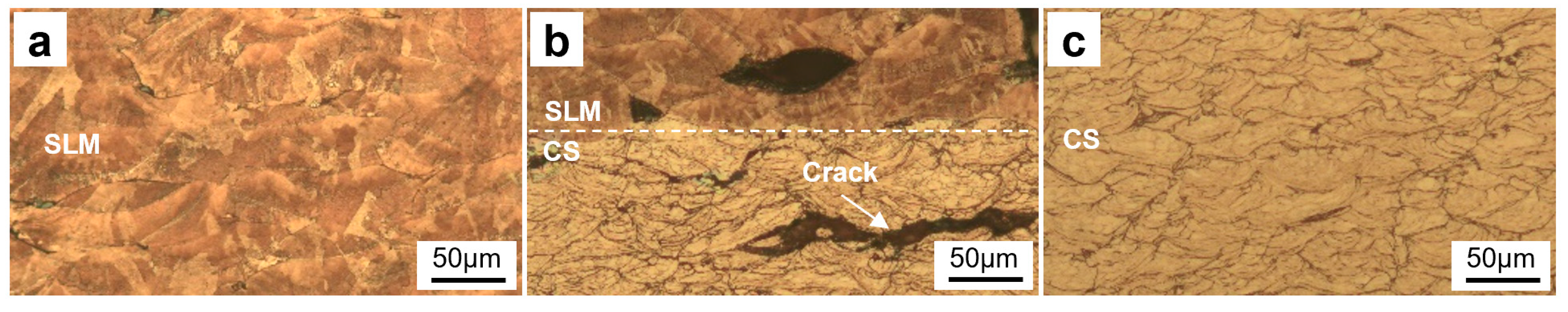
3.1. Microstructures of the Hybrid AM Sample (SLM Cu on as-Fabricated CS Cu)

Figure 4 shows the microscopic images of the interfacial microstructure of the SLM Cu deposited on as-fabricated CS Cu. As can be seen from the global view of the hybrid sample shown in Figure 4a, a large crack was found beneath the SLM/CS interface in the CS part, which almost detached the SLM part from the CS part. However, interestingly, the SLM/CS interface seems clear and well bonded, as shown in Figure 4b,c. The reason for the crack is possibly the high tensile residual stress generated in the CS part that was caused by the high energy density of the laser during the SLM process over the weak cohesion strength of the CS part [21]. It is well known that the strength of CS parts was normally much lower than the SLM counterparts since the interparticle bonding in CS parts is dominated by localized metallurgy and mechanical interlocking rather than complete metallurgy which dominates the interparticle bonding in SLM parts. Such a difference in microstructure can also be found in Figure 4c. The white dashed line in Figure 4c represents the interface between the SLM and CS parts. Due to the supersonic impact of the powder in the CS process, the deformed powder particle boundaries can be clearly seen below the dashed line. Above the dashed line, the boundaries of the powder particles are completely invisible, replaced by clear grain boundaries. In this study, interparticle boundaries that indicate incomplete metallurgical bonding between adjacent particles were clearly seen in the CS part after etching, while in the SLM part nearly all powder particles were fully melted to form complete metallurgy.
For further revealing the microstructural characteristics in the hybrid sample, Figure 5 shows the etched microstructure of the SLM/CS part. Clearly, there was a significant difference in microstructure between the CS part and the SLM part. For the SLM part, the boundaries between adjacent tracks can be clearly seen, together with some micro-pores, as shown in Figure 5a, which are the typical microstructure for SLM Cu. Due to the thermal effect of the laser, metallurgical bonding occurs among Cu particles. For the CS part in the as-fabricated state, the interparticle boundaries could be observed clearly after etching, as shown in Figure 5c. The particles in the CS part exhibit significant plastic deformation. The pores appearing in the SLM part of Figure 5b are a small number of local pores. From Figure 5a, it can be seen that there are few pores in the SLM part, while Figure 5c reflects the presence of more pores in the CS part. The CS part seems to have lower porosity than the SLM part. The SLM/CS interface shown in Figure 5b presents a large crack just beneath the interface. These findings are in consistent with the SEM observation shown in Figure 4.
During the hybrid AM process, the strength of the CS part is normally weak, as discussed above. The rapid local heat generation and high cooling rates typically result in significant thermal gradients, leading to the formation of greater residual stresses within the sample [22]. The main factor causing these residual stresses is the shrinkage that occurs after the laser processing. However, the colder CS part below limits this shrinkage, leading to the development of compressive stress at the top layer of the CS part (interface) and tensile stress below it [23]. Therefore, once the tensile residual stress exceeds the strength of the CS Cu part, cracks nucleate and propagate at the location where residual stress reaches the maximum [24,25,26]. Such cracks will be significantly harmful to the bonding strength between SLM and CS parts. Despite the formation of large crack in the CS part, the SLM/CS interface itself had no significant defects (e.g., large cracks and pores), as revealed by Figure 4b,c. The SLM part bonded well with the CS part. This phenomenon implies that it is feasible to deposit Cu on CS Cu via SLM as long as the formation of cracks is prevented. Our solution is, hence, to heat-treat the CS Cu part to improve its interparticle metallurgical bonding before it is subject to SLM processing, which will be described in the next section.

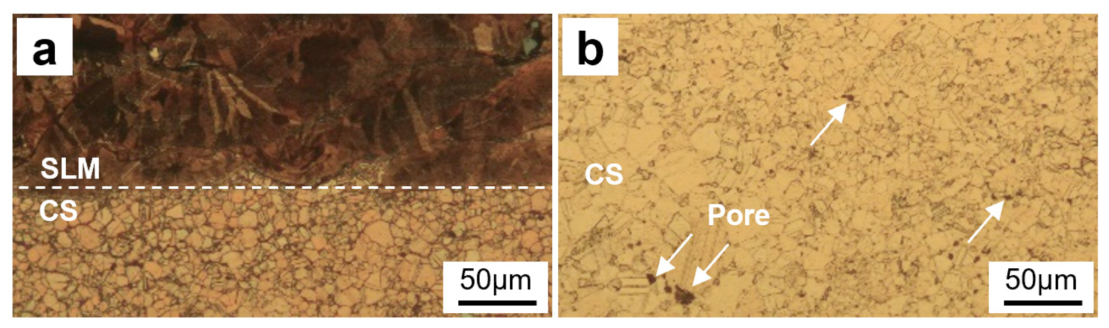
3.2. Microstructures of the Hybrid AM Sample (SLM Cu on Heat-Treated CS Cu)

Figure 6 shows the interfacial microstructures of the hybrid AM sample (SLM Cu on heat-treated CS Cu). The white dashed line is the boundary line of the SLM/CS interface. As can be seen, after the CS Cu substrate was heat-treated, the CS part remained intact with no cracks found beneath the SLM/CS interface. This is because the interparticle bonding and overall cohesion strength of the CS part were significantly improved after heat treatment. From Figure 6c, it can be seen that, due to the process without heat treatment in the SLM part, the microstructure displayed above the dashed line is consistent with Figure 4c. However, due to the heat treatment of the CS part, the microstructure below the dashed line underwent significant changes. The boundary between the powder particles in the CS part disappears. The stronger bond is formed in the material. This can be proved by the etched OM microstructure shown in Figure 7, where interparticle boundaries could not be observed anymore in the CS Cu part. Instead, the CS part was characterized by large equiaxed grains and twining due to the recovery and recrystallization during the heat treatment [27,28]. Therefore, even though the SLM process caused high residual stress in the CS part, the high cohesion strength is able to withstand the nucleation of cracks. In addition, it can also be seen from Figure 6 and Figure 7 that the SLM/CS interface exhibited good metallurgical bonding features and is free of significant metallurgical defects. These facts suggest that improving the CS Cu strength through conventional heat treatment can prevent the formation of cracks and provide good SLM/CS interfacial bonding.
According to the measurement of the porosity, the porosity of SLM parts in their as-fabricated state is approximately 0.27%, which is larger than that of CS parts at 0.07%, further confirms the lower density of SLM parts than that of CS parts. During the heat treatment process, there are chemical reactions occurring in the material which generate some oxides while generating even more pores. From Figure 7, we can see that pores were formed in the CS part after heat treatment. The following text also shows the generation of oxides after heat treatment. Therefore, the porosity of heat-treated SLM parts is increased compared to the as-fabricated state, estimated to be 0.68%, and it is also one of the important reasons for the sharp decrease in the hardness of the CS part after heat treatment. Another reason for the increase in porosity is the shrinkage of the material after the heat treatment. However, the stronger bond is formed in the material.

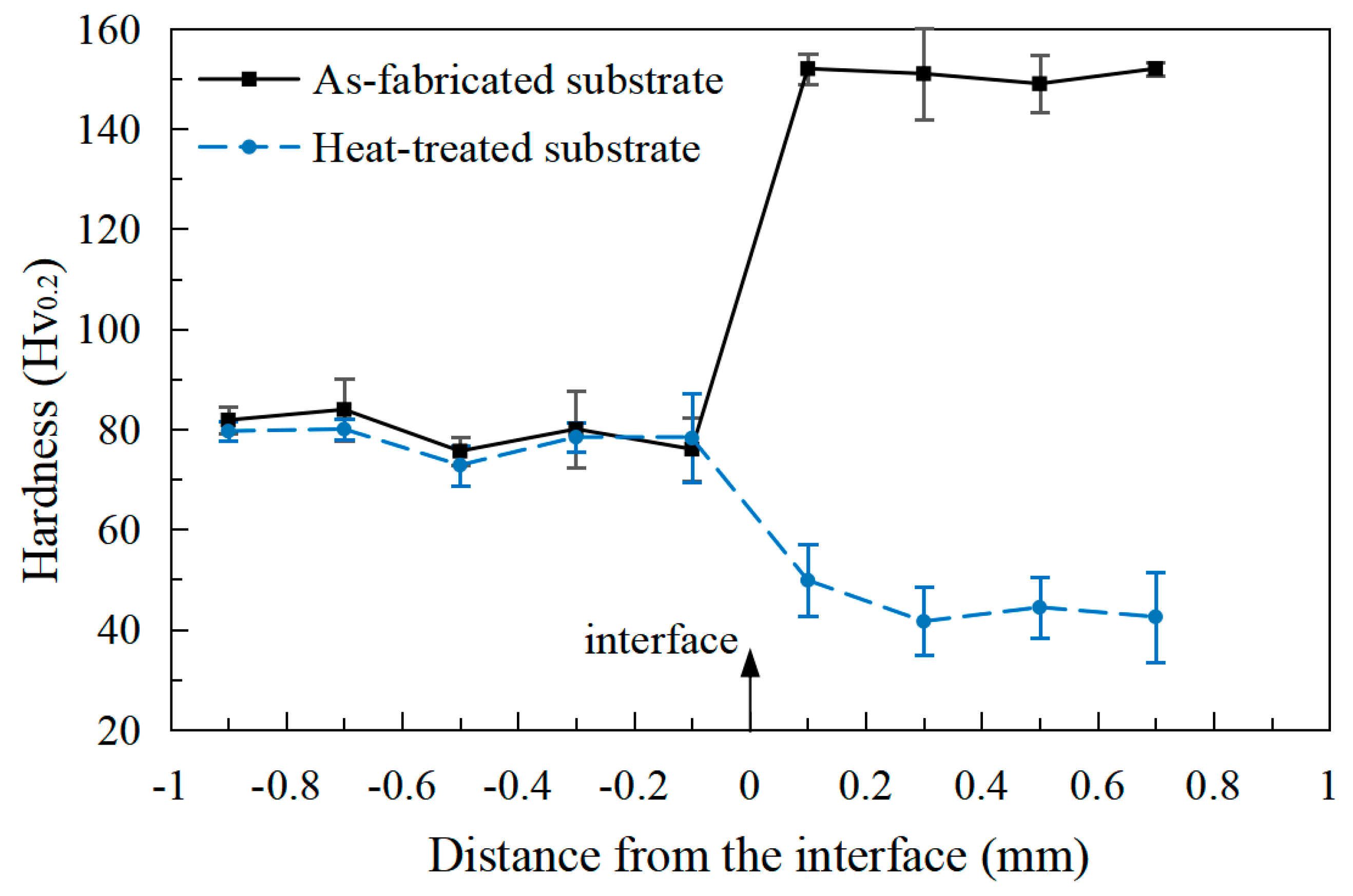
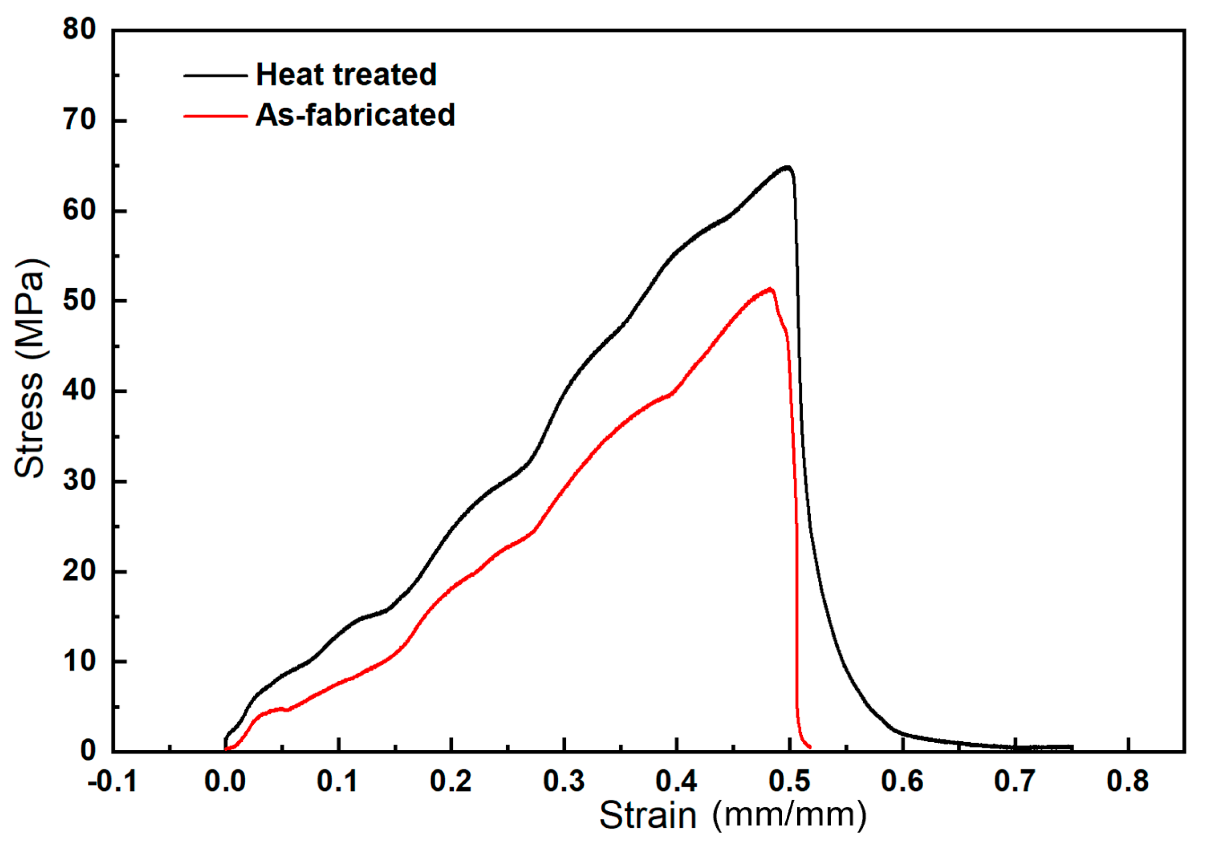
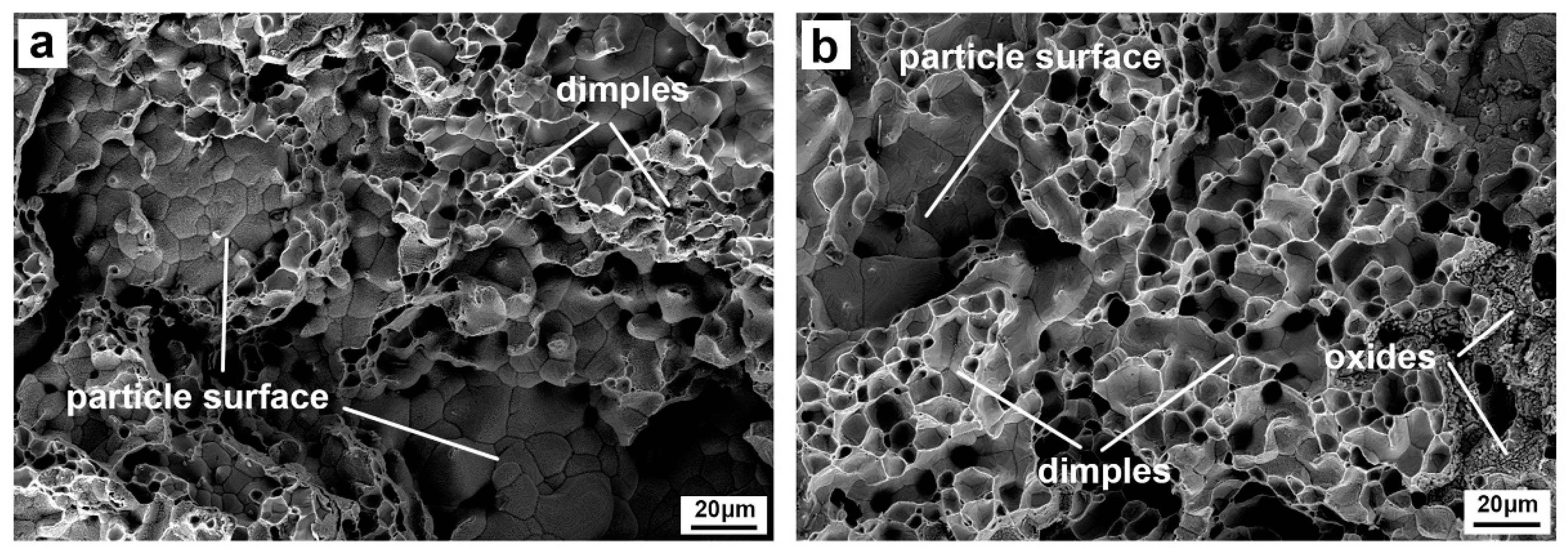
3.3. Hardness and Interfacial Bonding Strength of the Hybrid AM Cu Sample

Figure 8 shows the hardness of the two hybrid samples measured across the SLM/CS interface. For the SLM Cu on as-fabricated CS Cu, the hardness of the SLM part is relatively consistent, approximately 80 MPa. However, at the SLM/CS interface, there was a dramatic change in the hardness of the tested surface, from 80 HV0.2 to around 145 HV0.2. The hardness of the CS part is also relatively consistent, about 145 HV0.2. For the SLM Cu on heat-treated CS Cu, the hardness variation of the tested surface is exactly the opposite. The hardness at the SLM/CS interface sharply decreased from 80 HV0.2 to 40 HV0.2. Finally, the hardness of the CS part after heat treatment remains at 40 HV0.2. It is seen that heat treatment dramatically reduced the hardness of the CS part from 145 HV0.2 to 40 HV0.2 due to the grain growth and micro pores. After heat treatment, the hardness difference between the SLM and CS parts were reduced.
Section 3.1 and Section 3.2 of this study have yielded insights into the enhancement of interfacial bonding between the SLM and the CS parts through a strategic heat treatment of the CS part before SLM processing. The intention behind this approach was to systematically assess and quantify the improvements in interfacial bonding. In the following discourse, we delve into the details of this process and the mechanisms responsible for the observed changes.
Figure 9 presents the stress–strain curves of the tensile samples extracted from the interfaces, along with the corresponding average strength values. These results vividly illustrate the significant improvement in interfacial bonding strength. Prior to the heat treatment, the interfacial bonding strength was measured to be 45 ± 7 MPa. However, after the CS part underwent the prescribed heat treatment, this strength increased by an impressive 38% to 62 ± 1 MPa. This remarkable boost in interfacial bonding strength can be attributed to several factors, primarily centered around the effects of the heat treatment process. The enhancement in interfacial bonding strength after heat treatment can be directly correlated with the intensified mass diffusion and recrystallization occurring at the interface between the CS and SLM parts. These phenomena are consistent with the well-established principles of metallurgy, specifically the concepts of grain boundary migration and recrystallization that strengthen the bonds at the interface. These findings are consistent with prior research in the field [29,30,31], adding valuable insights to the existing body of knowledge.
In addition, it is also found that both samples fractured in the CS part rather than the interface, which indicates that the SLM/CS interfacial bonding is stronger than the CS parts even after heat treatment. The SLM/CS combination can withstand higher stresses without failure due to the superior bonding at the interface. For a deeper understanding of the fracture mechanism and the validation of the aforementioned findings, Figure 10 provides the SEM images of the fracture surfaces of the tensile samples. The fracture mechanism in the as-fabricated CS part exhibits a bi-modal pattern, characterized by a portion of the fractures occurring through the interparticle boundaries, as evidenced by smooth particle surfaces and equiaxed grains. The rest of the fractures are observed to traverse the particles themselves, as indicated by the presence of dimples on the fracture surfaces. However, in the heat-treated CS part, a noteworthy transformation is observed while the bi-modal fracture mechanism is still present. Notably, the heat treatment process leads to the formation of new oxides on the particle surfaces. These oxides play a crucial role in enhancing the bond at the interface. Furthermore, the presence of more dimples on the fracture surfaces of heat-treated specimens implies improved bonding, as dimples are characteristic of ductile failure and energy-absorbing mechanisms.
The results from Section 3.1 and Section 3.2 confirm that the application of heat treatment to the CS part before SLM processing leads to a significant improvement in interfacial bonding strength. This improvement can be attributed to enhanced mass diffusion, recrystallization, and the formation of new oxides at the interface. The fact that fractures occurred primarily within the CS part, even after heat treatment, underscores the effectiveness of the SLM/CS interfacial bonding. These findings shed light on the promising prospects of utilizing heat treatment as a means to strengthen the interfacial bonding between the SLM and CS components.

4. Conclusions

This paper presents a hybrid additive manufacturing (AM) process, combining fusion-based selective laser melting (SLM) and solid-state cold spraying (CS), for producing near-net-shape metal parts with high speed. The process begins with the deposition of a bulk deposit with a rough contour via the “fast” CS process, and then fine structures and complex features are added via the “slow” SLM process. It was found that SLM processing onto CS parts can lead to good interfacial bonding, but the CS parts must undergo heat treatment to improve the cohesion strength prior to SLM processing. Without addressing the high tensile residual stress caused by the SLM process, fractures and cracks may occur in the CS part. Applicable heat treatment conditions can transform the mechanical engagement of the CS part into metallurgical bonding and produce some high-strength oxides, thereby improving the bonding strength and reducing the cracks in the CS part. The results from the tensile tests on the SLM/CS interfaces indicated that the bonding strength increased by 38% from 45 ± 7 MPa to 62 ± 1 MPa following heat treatment. This study provides evidence that the proposed hybrid AM process is feasible and promising for the rapid production of free-standing SLM-CS components.

Author Contributions

Methodology, Q.C., Y.X., X.Y., and S.Y.; conceptualization, C.H., Y.X., R.L., and C.Z.; investigation Q.C., C.J., and C.H.; validation C.J. and R.L.; formal analysis, C.J., C.H., X.Y., R.L., and P.R.; data curation, Q.C., Y.X., X.Y., C.Z., and P.R.; writing—original draft, Q.C. and S.Y.; writing—review and editing, S.Y. and P.R.; supervision, C.Z. and S.Y.; funding acquisition, Y.X. All authors have read and agreed to the published version of the manuscript.

Funding

This research was funded by [Guangdong Academy of Sciences Special Fund for Comprehensive Industrial Technology Innovation Center Building] grant number [2022GDASZH-2022010107] and [GDAS’ project of Science and Technology Development] grant number [2022GDASZH-2022010203-003].

Data Availability Statement

The data presented in this study are available on request from the corresponding author.

Acknowledgments

We acknowledge the financial support.

Conflicts of Interest

The authors declare no conflict of interest.

References

  1. Jadhav, S.; Dadbakhsh, S.; Goossens, L.; Kruth, J.; Humbeeck, J.; Vanmeensel, K. Influence of selective laser melting process parameters on texture evolution in pure copper. J. Mater. Process. Technol. 2019, 270, 47–58. [Google Scholar] [CrossRef]
  2. Colopi, M.; Caprio, L.; Demir, A.; Previtali, B. Selective laser melting of pure Cu with a 1 kW single mode fiber laser. Procedia CIRP 2018, 74, 59–63. [Google Scholar] [CrossRef]
  3. Sun, Z.; Tan, X.; Tor, S.; Yeong, W. Selective laser melting of stainless steel 316L with low porosity and high build rates. Mater. Des. 2017, 126, 197–204. [Google Scholar] [CrossRef]
  4. Liverani, E.; Toschi, S.; Ceschini, L.; Fortunato, A. Effect of selective laser melting (SLM) process parameters on microstructure and mechanical properties of 316L austenitic stainless steel. J. Mater. Process. Technol. 2017, 249, 255–263. [Google Scholar] [CrossRef]
  5. Jia, G.; Yang, H.; Zhang, H.; Xu, S.; Peng, T.; Zhu, Y. Electrical energy consumption and mechanical properties of selective-laser-melting-produced 316L stainless steel samples using various processing parameters. J. Clean. Prod. 2018, 208, 77–85. [Google Scholar] [CrossRef]
  6. Wang, J.; Zhu, R.; Liu, Y.; Zhang, L. Understanding melt pool characteristics in laser powder bed fusion: An overview of single- and multi-track melt pools for process optimization. Adv. Powder Mater. 2023, 2, 100137. [Google Scholar] [CrossRef]
  7. Zhang, L.; Chen, L.; Zhou, S.; Luo, Z. Powder bed fusion manufacturing of beta-type titanium alloys for biomedical implant applications: A review. J. Alloys Compd. 2023, 936, 168099. [Google Scholar] [CrossRef]
  8. Bai, C.; Lan, L.; Xin, R.; Gao, S.; He, B. Microstructure evolution and cyclic deformation behavior of Ti-6Al-4 V alloy via electron beam melting during low cycle fatigue. Int. J. Fatigue 2022, 159, 106784. [Google Scholar] [CrossRef]
  9. Wang, Y.; Voisin, T.; McKeown, J.; Ye, J.; Calta, N.; Li, Z.; Zeng, Z.; Zhang, Y.; Chen, W.; Roehling, T.; et al. Additively manufactured hierarchical stainless steels with high strength and ductility. Nat. Mater. 2018, 17, 63–71. [Google Scholar] [CrossRef]
  10. Saeidi, K.; Gao, X.; Lofaj, F.; Kvetková, L.; Shen, Z. Transformation of austenite to duplex austenite-ferrite assembly in annealed stainless steel 316L consolidated by laser melting. J. Alloys Compd. 2015, 633, 463–469. [Google Scholar] [CrossRef]
  11. Kong, D.; Dong, C.; Ni, X.; Zhang, L.; Yao, J.; Man, C.; Cheng, X.; Xiao, K.; Li, X. Mechanical properties and corrosion behavior of selective laser melted 316L stainless steel after different heat treatment processes. J. Mater. Sci. Technol. 2019, 35, 1499–1507. [Google Scholar] [CrossRef]
  12. Guo, S.; Lu, Y.; Wu, S.; Liu, L.; He, M.; Zhao, C.; Gan, Y.; Lin, J.; Luo, J.; Xu, X.; et al. Preliminary study on the corrosion resistance, antibacterial activity and cytotoxicity of selective-laser-melted Ti6Al4V-xCu alloys. Mater. Sci. Eng. C 2017, 72, 631–640. [Google Scholar] [CrossRef] [PubMed]
  13. Herzog, D.; Seyda, V.; Wycisk, E.; Emmelmann, C. Additive manufacturing of metals. Acta Mater. 2016, 117, 371–392. [Google Scholar] [CrossRef]
  14. Yuan, W.; Li, R.; Chen, Z.; Gu, J.; Tian, Y. A comparative study on microstructure and properties of traditional laser cladding and high-speed laser cladding of Ni45 alloy coatings. Surf. Coat. Technol. 2020, 405, 126582. [Google Scholar] [CrossRef]
  15. Xi, W.; Song, B.; Zhao, Y.; Yu, T.; Wang, J. Geometry and dilution rate analysis and prediction of laser cladding. Int. J. Adv. Manuf. Technol. 2019, 103, 4695–4702. [Google Scholar] [CrossRef]
  16. Wang, Q.; Ma, N.; Luo, X.; Li, C. Capturing cold-spray bonding features of pure Cu from in situ deformation behavior using a high-accuracy material model. Surf. Coat. Technol. 2021, 413, 127087. [Google Scholar] [CrossRef]
  17. Yin, S.; Yan, X.; Chen, C.; Jenkins, R.; Liu, M.; Lupoi, R. Hybrid additive manufacturing of Al-Ti6Al4V functionally graded materials with selective laser melting and cold spraying. J. Mater. Process. Technol. 2018, 255, 650–655. [Google Scholar] [CrossRef]
  18. Yin, S.; Cavaliere, P.; Aldwell, B.; Jenkins, R.; Liao, H.; Li, W.; Lupoi, R. Cold spray additive manufacturing and repair: Fundamentals and applications. Addit. Manuf. 2018, 21, 628–650. [Google Scholar] [CrossRef]
  19. Ozdemir, O.; Widener, C.; Carter, M.; Johnson, K. Predicting the effects of powder feeding rates on particle impact conditions and cold spray deposited coatings. J. Therm. Spray Technol. 2017, 264, 1598–1615. [Google Scholar] [CrossRef]
  20. Yin, S.; Jenkins, R.; Yan, X.; Lupoi, R. Microstructure and mechanical anisotropy of additively manufactured cold spray copper deposits. Mater. Sci. Eng. A 2018, 7349, 67–76. [Google Scholar] [CrossRef]
  21. Rttger, A.; Geenen, K.; Windmann, M.; Binner, F.; Theisen, W. Comparison of microstructure and mechanical properties of 316L austenitic steel processed by selective laser melting with hot-isostatic pressed and cast material. Mater. Sci. Eng. A 2016, 678, 365–376. [Google Scholar] [CrossRef]
  22. Li, C.; Liu, J.F.; Guo, Y.B. Prediction of Residual Stress and Part Distortion in Selective Laser Melting. Procedia CIRP 2016, 45, 171–174. [Google Scholar] [CrossRef]
  23. Lu, W.; Liu, Y.; Wu, X.; Liu, X.; Wang, J. Corrosion and passivation behavior of Ti-6Al-4V surfaces treated with high-energy pulsed laser: A comparative study of cast and 3D-printed specimens in a NaCl solution. Surf. Coat. Technol. 2023, 470, 129849. [Google Scholar] [CrossRef]
  24. Xie, D.; Lv, F.; Yang, Y.; Shen, L.; Tian, Z.; Shuai, C.; Chen, B.; Zhao, J. A Review on Distortion and Residual Stress in Additive Manufacturing. Chin. J. Mech. Eng. Addit. Manuf. Front. 2022, 1, 10039. [Google Scholar] [CrossRef]
  25. Gu, D.D.; Meiners, W.; Wissenbach, K.; Poprawe, R. Laser additive manufacturing of metallic components: Materials, processes and mechanisms. Int. Mater. Rev. 2012, 57, 133–164. [Google Scholar] [CrossRef]
  26. Yadroitsev, I.; Yadroitsava, I. Evaluation of residual stress in stainless steel 316L and Ti6Al4V samples produced by selective laser melting. Virtual Phys. Prototyp. 2015, 10, 67–76. [Google Scholar] [CrossRef]
  27. Yan, X.; Chang, C.; Dong, D.; Gao, S.; Ma, W.; Liu, M.; Liao, H.; Yin, S. Microstructure and mechanical properties of pure copper manufactured by selective laser melting. Mater. Sci. Eng. A 2020, 789, 139615. [Google Scholar] [CrossRef]
  28. Haubrich, J.; Gussone, J.; Barriobero-Vila, P.; Kürnsteiner, P.; Jägle, E.; Raabe, D.; Schell, N.; Requena, G. The role of lattice defects, element partitioning and intrinsic heat effects on the microstructure in selective laser melted Ti-6Al-4V. Acta Mater. 2019, 167, 136–148. [Google Scholar] [CrossRef]
  29. Li, Y.; Liang, X.; Yu, Y.; Wang, D.; Lin, F. Review on Additive Manufacturing of Single-Crystal Nickel-based Superalloys. Chin. J. Mech. Eng. Addit. Manuf. Front. 2022, 1, 100019. [Google Scholar] [CrossRef]
  30. Ci, S.; Liang, J.; Li, J.; Zhou, Y.; Sun, X. Microstructure and tensile properties of DD32 single crystal Ni-base superalloy repaired by laser metal forming. J. Mater. Sci. Technol. 2020, 45, 23–34. [Google Scholar] [CrossRef]
  31. Yin, S.; Fan, N.; Huang, C.; Xie, Y.; Zhang, C.; Lupoi, R.; Li, W. Towards high-strength cold spray additive manufactured metals: Methods, mechanisms, and properties. J. Mater. Sci. Technol. 2024, 170, 47–64. [Google Scholar] [CrossRef]
Figure 1. The flowchart of the hybrid AM process.
Jmmp 07 00188 g001
Figure 2. The morphology of the Cu powders used for SLM and CS.
Jmmp 07 00188 g002
Figure 3. (a) The photo of the hybrid AM Cu part, (b) non-standard dog-bone tensile sample, and (c) dimensional diagram of the tensile specimen.
Jmmp 07 00188 g003
Figure 4. Interfacial microstructure of the hybrid SLM Cu on as-fabricated CS Cu observed using SEM. (a) Global view of the SLM/CS part, (b) local SLM/CS interface, (c) etched local SLM/CS interface.
Jmmp 07 00188 g004
Figure 5. The cross-sectional microstructure of the hybrid SLM Cu on as-fabricated CS Cu after etching observed via OM. (a) SLM part, (b) SLM/CS interface, and (c) CS part.
Jmmp 07 00188 g005
Figure 6. Interfacial microstructure of the hybrid SLM Cu on heat-treated CS Cu observed via SEM. (a) Global view of the SLM/CS part, (b) local SLM/CS interface, (c) etched local SLM/CS interface.
Jmmp 07 00188 g006
Figure 7. The cross-sectional microstructure of the hybrid SLM Cu on heat-treated CS Cu after etching observed via OM. (a) SLM/CS interface, (b) CS part.
Jmmp 07 00188 g007
Figure 8. Hardness of the two hybrid samples measured across the SLM/CS interface.
Jmmp 07 00188 g008
Figure 9. Stress–strain curves of the tensile samples extracted from the interfaces and the corresponding average strength.
Jmmp 07 00188 g009
Figure 10. SEM images of the fracture surfaces of the tensile samples. (a) The as-fabricated CS part, (b) the heat-treated CS part.
Jmmp 07 00188 g010
Table 1. Manufacturing parameters of the hybrid AM process.
CSGasPressureTemperatureStandoff DistanceHatch DistanceNozzle Moving Speed
N23.0 MPa800 °C35 mm3.5 mm50 mm/s
SLMChamberLaser spot diameterLaser powerLayer thicknessHatch distanceLaser moving speed
Ar100 μm300 W30 μm80 μm1.0 m/s
Disclaimer/Publisher’s Note: The statements, opinions and data contained in all publications are solely those of the individual author(s) and contributor(s) and not of MDPI and/or the editor(s). MDPI and/or the editor(s) disclaim responsibility for any injury to people or property resulting from any ideas, methods, instructions or products referred to in the content.

