Article

Filament Development for Laser Assisted FFF 3D Printing

1
Department of Industrial and Manufacturing Engineering, University of Malta, 2080 Msida, Malta
2
Faculty of Agricultural and Environmental Sciences, Hungarian University of Agriculture and Life Sciences (MATE), 3200 Gyöngyös, Hungary
*
Author to whom correspondence should be addressed.
J. Manuf. Mater. Process. 2021, 5(4), 115; https://doi.org/10.3390/jmmp5040115
Submission received: 27 September 2021 / Revised: 26 October 2021 / Accepted: 27 October 2021 / Published: 29 October 2021

Abstract

:
The aim of this paper was to develop filaments which can be used for laser assisted fused filament fabrication (FFF) 3D printing in order to increase the inter-layer bonding strength of the printed part. The filaments were developed from the most commonly used filament materials, acrylonitrile butadiene styrene (ABS) and polylactic acid (PLA) with the addition of different polymer additives. After performing near infrared (NIR) absorption tests, graphite was selected for further development as it possesses excellent NIR absorption capabilities whilst resulting in consistent filaments’ diameter and being economically viable. A conventional FFF 3D printer was initially used to test the printability of the developed filaments. Afterwards, a fiber couple laser diode was integrated within the printing head to heat up the previously extruded layer. The produced filaments were used to 3D print specimens for shear and tensile testing. With the laser heating, an increase of 14.5% in the elastic modulus and an increase of 27.8% in the tensile strength of the printed parts were noticed. This showed that adding additives into filament materials for localized laser heating is an effective method of increasing the inter-layer bonding, and therefore, the overall strength and durability of FFF 3D printed parts.

1. Introduction

Fused Filament Fabrication (FFF) forms part of the most common additive manufacturing process, namely 3D printing. This process transforms a spooled filament into a 3D part by melting the material and extruding it into a 3D object [1,2].
The major drawbacks of FFF 3D printing are due to unsatisfactory mechanical properties wherein the printed parts lack long-term durability. In FFF 3D printing, the part is manufactured through a layer-by-layer extrusion technique which will inevitably create weak spots between the layers since a molten layer is extruded onto the previously deposited layer (which would have cooled to a temperature well below the polymer molten temperature) [3,4,5]. Recently, the integration of laser energy within 3D printing technology has been introduced, most notably within FFF where laser energy is used to heat the previously extruded layer prior to the deposition of the next layer.
Although the above-mentioned integration of laser energy to reheat deposited layers exists, the effort to increase the laser absorption by adding laser absorbing additives into the polymer for such a laser assisted FFF 3D printing has not yet been made. The goal of this study was therefore to increase the adhesive bond strength between the layers, thus making the printed part stronger and more durable through the addition of laser heating and NIR absorbing polymer additives.

In-Process Laser Heating

The relationship between the FFF 3D printing process parameters and the bonding formation between the printed layers was investigated. After meticulous research [4,5], it was concluded that the most critical factors that directly affect the layer bonding strength are the temperature of the nozzle, the temperature of the surrounding build environment, and the transfer of heat surrounding the bond site. Of these factors, the most important is the build environment temperature. Increasing the build environment temperature will directly increase the inter-layer bond strength of the filament. However, the ramification of such action will prove to be detrimental to the structural accuracy and part dimension of the part [6].
After reviewing the relevant literature, mainly [6,7], it was concluded that the temperature of the critical interface must not only be reached but also maintained for a critical time duration in order to obtain adequate bond formation between the previously deposited layer and the next filament layer being extruded onto it. The critical interface temperature must be maintained in order to allow the three stages of bonding formation. First there is wetting, followed by diffusion, and finally randomization [7]. In this research, the localized laser heating on the previously deposited layer was investigated where lasers are used to supply the thermal energy on to a localized, focused spot on the part’s surface (as can be seen in Figure 1). In their study, the previously extruded layer is placed in front of the travelling extrusion nozzle just before depositing the next layer. Once the polymer was extruded and came into contact with the localized, laser heated region, wetting, diffusion, and randomization stages occur. These three stages directly resulted in an increase in the interlayer bonding strength by up to 50%.
In current FFF 3D printers, the highest temperature around the build envelop is around half of the glass transition temperature (Tg) of the filament’s polymer material in order to prevent geometrical and dimensional issues. However, due to the fact that laser preheating is extremely localized on a specific bond site, the heating temperatures can be well above Tg without any negative impacts on the part’s geometry and dimension. Besides the increase in inter-layer bond strength, the inter-layer interface becomes ductile as a result of the increase in the bonding of the inter-layer interface due to the rise in interface temperature and interpenetrating diffusion [7,8].
The increase in the part’s inter-layer strength is mainly due to the healing of the interface as a result of higher reptation and entanglement of the polymer chains when in presence of laser heating on the previously deposited layer. Reptation refers to the thermal motion of the linearly long and entangled macromolecules within the polymer melt. It is apparent that the strength in inter-layer bonding resulted from the increased temperature as it promoted time-dependent relaxation of the polymer. The obtained results which were reviewed from the literature show that laser pre-deposition heating is a feasible method to improve the isotropy of the FFF 3D printed part [6].

2. Filament Development

2.1. Polymers and Additives

It was decided that semi-crystalline PLA and amorphous ABS would be used as the raw polymeric materials for the filaments as these are the most commonly used polymers for FFF 3D printing [9,10]. The grade of polymers to be used for filament development were PLA 4043D and ABS 3453. The PLA 4043D is a multipurpose extrusion grade that can be converted into 3D printer monofilament and is known as a grade that well-suited for 3D printing applications. Although the ABS 3453 grade is generally used within injection molding, this grade of ABS was selected due to its variety of applications and its good flowability which makes it suitable for filament extrusion. The properties of both materials which are relevant for this research can be seen in Table 1. Both ABS and PLA are hydroscopic, and therefore, prior to filament development, both materials were dried to ensure that the desired filament quality would be achieved.
The next systematic step was to identify the required laser output and respective wavelength. The optimal wavelength for both PLA and ABS lies at a range of 450 ± 50 nm, as at this wavelength, optimal absorbance was achieved. In order to obtain this range of wavelength, blue diode lasers are required. However, these lasers are extremely expensive and will not be suitable to implement on a larger scale.
Therefore, an alternative, fiber coupled infrared laser diode was selected. This laser operated at a wavelength range of 900 ± 50 nm, which was found to be the second best with regard to the optimal wavelength for PLA and ABS. Hence, it was concluded that fiber coupled infrared laser diode would be selected as they were cost effective compared to the blue laser diode. The wavelength range of 900 ± 50 nm falls within the infrared region. However, the fiber coupled laser diode does not promote optimal absorbance in PLA and ABS, and therefore polymer additives would need to be added to the raw materials to promote NIR absorbance [13].
Hence, a suitable additive should be selected to be added with the polymers to promote infrared absorption. Additives were researched in order to find potential additives which would promote NIR absorption within the filaments. The selected additives were graphite, CNT, and Luniri1®. The latter (Luniri1®) is an NIR absorbing pigment with an absorption region of 800–1100 nm which is usually used in the manufacturing of currency. Graphite and carbon nanotubes dependent on their shape and size possess high absorption in the visible light range (~380–740 nm), which makes them black. It is highly possible that their absorption value does not change significantly for the 900 nm wavelength [13,14,15]. In contrast to graphite and carbon nano tubes, Luniri1® is transparent, which was one of the reasons for the selection of this additive. Besides NIR light absorption, another selection criterion was considered, namely the price. Table 2 shows the difference in cost to purchase of the different additives. Although the price of carbon nano tubes is relatively high, studies indicate that they possess remarkable mechanical properties, including an elastic modulus near 1000 GPa and tensile strength of several tens of GPa, which is similar to sheets of graphite ones [16]. Thus, it was decided to include carbon nano tubes in this study.

2.2. Filament Making

2.2.1. Filament Maker

The filament maker used for this research was the 3Devo’s composer 450 which is a compact, desktop filament maker. As can be seen in Figure 2, the filament maker consists of a hopper, an extruder, cooling fans, a diameter sensor, a positioner, and a filament winder. All of these components are controlled by the user via the control panel during the filament extrusion process [17].

2.2.2. Processing Parameters

The three most important processing parameters during filament extrusion are the heating element, the screw speed, and the cooling fans.
The heating element, which comprises of four identical heaters, is directly responsible for melting the raw material whilst being transferred inside the extruder screw. If the temperature of the heaters is too low, the raw pellets will not melt completely and may even cause blockage in the extruder nozzle. On the other hand, if the temperature is too high, the material will either burn inside the extruder screw or else be extruded in a way that makes it extremely difficult to maintain the filament’s diameter or even spool the filament [17].
The speed of the extruder screw, expressed in revolutions per minute (RPM), directly controls the material throughput being extruded from the nozzle. If the screw’s RPM is above its optimal setting, the material throughput will be excessive, resulting in a higher filament diameter.
On the contrary, if the screw’s RPM is below its optimal setting, the material throughput will be too low, resulting in a lower filament diameter. The temperatures of the heating element will also directly affect the optimal speed of the screw as the viscosity of the material is directly proportional to the material’s throughput at the nozzle [18].
As soon as the material is extruded from the nozzle and is in a liquid state, it must be cooled down to a temperature which allows for a uniform filament formation. When the speed of the cooling fans is too low, the material will be too soft at the diameter sensor which results in the filament being deformed and thus will not have a circular cross section. If the speed is too high, and the material cools down too much, it will not allow the filament’s cross-sectional diameter to be altered at the diameter sensor since it will be too hard to change its cross section. The ambient temperature will have a significant impact on the optimal speed of the cooling fans. When the filament was being developed at a room temperature of around 25 °C, the optimal cooling speed for the fans was found to be at around 60%. On the contrary, when the filament was being developed at an ambient temperature of around 15 °C, the optimal speed was found to be at around 30% due to the filament being cooled further due to the ambient temperatures [19,20].

2.2.3. Filament Extrusion with PLA

Prior to filament development, the raw PLA pellets were dried at a temperature of 80 °C for a drying period of four hours so as to ensure that the moisture content of the raw material was within the required limits. The selected additives were added with the raw PLA at the correct amounts. Due to the extreme volume difference between the pellets and the additives, it was extremely difficult to ensure homogeneous mixing. The filaments were then developed using the processing parameters which can be seen in Table 3. The extruder screw speed was optimized for each different filament mixture [20,21].
As seen in Table 3, the screw speed was varied with different additive combinations in order to achieve the desired consistent diameter. The additives directly affected the viscosity of the filament mixture and, therefore, the screw speed had to be varied in order to counteract for the change in material viscosity. The addition of graphite powder did not have any significant impact on the filament’s viscosity. However, CNT and even more so, Luniri1®, reduced the overall filament’s viscosity. Therefore, the screw speed had to be increased to counteract such change in the material’s properties [19,21].
In general, it was extremely strenuous to achieve a constant filament diameter of 1.75 mm. When extruding raw PLA, a decent tolerance of around ±0.05 mm was achieved.
Extruding PLA with 1% and 2% Luniri1® was slightly more challenging and after plenty of parameter experimentation, a tolerance of around ±0.1 mm was achieved. When extruding PLA with 1% and 2% graphite, similar results to Luniri1® were achieved.
However, as can be clearly seen in Figure 3, it was extremely difficult to maintain a consistent filament diameter when extruding PLA with CNT. The PLA with 1% CNT filament was varying up to ±0.25 mm, and this can be clearly seen in Figure 3, where the filament is evidently thinner and more inconsistent than all the other extruded filaments. It can be assumed that the CNT particles could not be dispersed properly in the polymer melt using the filament maker. Therefore, further research in the future to improve the CNT particle dispersion is necessary so that the tolerances would be within an acceptable limit.

2.2.4. Filament Extrusion with ABS

Similar to PLA, ABS pellets were dried at a temperature of 90 °C for a drying period of four hours so as to ensure that the moisture content of the raw material was within the acceptable limits. The selected additives were added with the raw ABS at the correct amounts. It is worth mentioning that due to the extreme volume difference between the pellets and the additives, it was tremendously arduous to ensure homogeneous mixing. The filaments were then developed using the processing parameters which can be seen in Table 4. The extruder screw speed was varied for each different filament mixture.
As seen in Table 4, the heating temperatures were kept constant for all different material combination and only the screw speed was varied in order to achieve the desired consistent diameter. The additives directly affected the viscosity of the filament mixture and therefore, the screw speed had to be varied in order to counteract for the change in material viscosity. The addition of graphite powder CNT and Luniri1®, reduced the overall filament’s viscosity. Consequently, the screw speed had to be increased to counteract such a change in the material’s properties.
When comparing with PLA filament development, it was slightly easier to achieve a constant filament diameter of 1.75 mm with ABS. When extruding raw ABS, a decent tolerance of around ±0.05 mm was achieved. Extruding ABS with 1% and 2% graphite also achieved admirable results with a tolerance similar to raw ABS, at around ±0.05 mm. When extruding ABS with 1% and 2% Luniri1®, the tolerance was still within an acceptable limit of around ±0.1 mm.
However, as can be clearly seen in Figure 4, it was extremely difficult to maintain a consistent filament diameter when extruding ABS with CNT, similar to what was noticed when extruding PLA with CNT. The ABS with 1% CNT filament proved to be the most difficult since the filament diameter was varying up to ±0.25 mm. This can be clearly seen in Figure 4, where the filament is evidently thinner and inconsistent especially when being compared to other extruded filaments. Therefore, it was clear that if CNT would be chosen for further filament development, more time would need to be dedicated in order to fully optimize the process parameters of the filament development with the aim of tightening the tolerance to an acceptable limit (around ±0.1 mm).
In general, it was exceedingly exacting to extrude filament with a consistent diameter. As mentioned in the above section, it was decided that only the extruder screw speed would be varied during the filament development in order to not allow process parameter bias to skew the filament development process.

2.3. Filament Characterization and Selection

2.3.1. Filament Characterization Using DMA

A dynamic mechanical analyzer (DMA) from Mettler Toledo (DMA 1) was used on the different filaments in order to characterize them with the aim of understanding the effects of the additives on the raw filaments. The DMA test for all filaments was carried out in tension mode with a displacement of 10 µm and a frequency of 1 Hz. The PLA based filaments were tested from a starting temperature of 20 °C up to a temperature of 150 °C with a heating rate of 2 K/minute. Similarly, the ABS based filaments were tested from a starting temperature of 20 °C up to a temperature of 170 °C with a heating rate of 2 K/minute. The ABS based filaments were tested at greater temperatures than PLA based filaments due to the temperature difference (since the Tg of ABS is significantly higher than that of PLA).
Filament characterization was carried out using the DMA on all the different filament extrusions. For PLA based filaments, the glass transition temperature, represented by Tg, is an approximation within the glass transition range since glass transition will occur at a range of temperatures rather than at a single point. The approximate Tg for the PLA + 2% graphite filament is around 60 °C. This Tg approximation is further supported by literature. When the filament is heated above the glass transition range, approximately above 70 °C, the polymer will enter a rubbery plateau which is between Tg and the polymer reaching its melting temperature, Tm.
As can be seen in Figure 5 and Figure 6, due to the amorphous structure of ABS, the heat energy required to change from a solid to a glassy state is higher than that of PLA. Hence the glass transition temperature range is between 90 °C and 110 °C. The typical Tg for ABS was taken to be approximately 100 °C, which is similar to what was expected from literature. The discrepancy in the DMA results of both PLA and ABS filaments with different additives is caused by the diameter inconsistency of the filaments during extrusion.
As previously shown in Figure 4, the ABS + 2% graphite filaments showed negligibly minor inconsistency in the filaments’ diameter which reflects the relatively consistent DMA results as can be seen in Figure 7.

2.3.2. Filament Characterization Using DSC

For this test, a differential scanning calorimeter (DSC) from Mettler Toledo (DSC3+) was used on the different filaments in order to fully understand the effects of the additives on the raw filaments.
Given the fact that PLA is semicrystalline and ABS is amorphous, the heating cycles were different. The ABS based filaments were only subjected to a single heating test with an initial starting temperature 25 °C up to temperature of 160 °C with a heating rate of 2 K/minute. Only a single heating was performed on ABS based filaments due to the fact that since it is amorphous, there is limited results which can be extracted from DSC tests. PLA was subjected to a completely different heating cycle which consisted of heating up to a temperature of 180 °C with a heating rate of 2 °C/minute and cooling to a temperate of 25 °C, followed by a second heating in order to investigate the difference to the material’s characteristics between the two heating cycles.
As seen in Figure 8, every heating cycle for PLA consisted of two endothermic peaks and one exothermic trough. In an endothermic peak, heat energy is drawn into the filament whereas in an exothermic trough heat energy is released from the filament to its surroundings.
The first endothermic peak of the first heating represents the glass transition range. The peak temperature will be the taken as the Tg of the material [22]. The area under this peak can be found by integrating the curve of the peak. This area will represent the heat energy, Hg required for the filament to generate a phase change, from a solid to a glassy state.
The second reference identified during the first heating is the exothermic trough as seen in Figure 8. This exothermic trough shows heat energy being released during the cold crystallization range. Heat is being released due to conformational energy where the molecules will be arranging themselves into a lower energy configuration. As the temperature is increased to the cold crystallization range, the molecules will gain order. The peak of the trough during the cold crystallization range is expressed as Tcc. As the molecules gain order, they run into a crystalline structure whilst releasing energy, given as cold crystallization enthalpy, Hcc. The greater the Hcc, the greater is the degree of crystallinity, Xc of the material.
The third reference was the second endothermic and the largest peak which represents the melting range. This peak represents the heat energy required, Hm to generate a phase change where the molecules change from crystals to amorphous. Since the PLA is semi-crystalline, crystals are formed during the cold crystallization range, and these will exhibit randomization once the temperature is within the melting range. The temperature at the peak is the Tm and at this temperature, the molecules are fully amorphous as the polymer is molten. Table 5 shows the obtained results from the DSC thermograms for PLA based filaments with different polymer additives.
When studying the DSC thermograms, another significant material property can be evaluated, the degree of crystallinity, Xc. The Xc is dependent on the Hm, found in Table 5 and the theoretical melting enthalpy of 100% crystalline PLA (H100%), namely 93 J/g [23]. These parameters are related to one another as expressed in the follow equation:
                                          X c = H m H 100 × 100 %
The Xc of all different filaments were calculated using Equation (1) and their results can be seen in Table 6.
As expected, since the Hm during the second heating was significantly lower for all filaments, the Xc is also significantly lower when compared with the first heating. The PLA filaments with the CNT additives showed a significantly greater Xc for either heating when compared with the other additives.

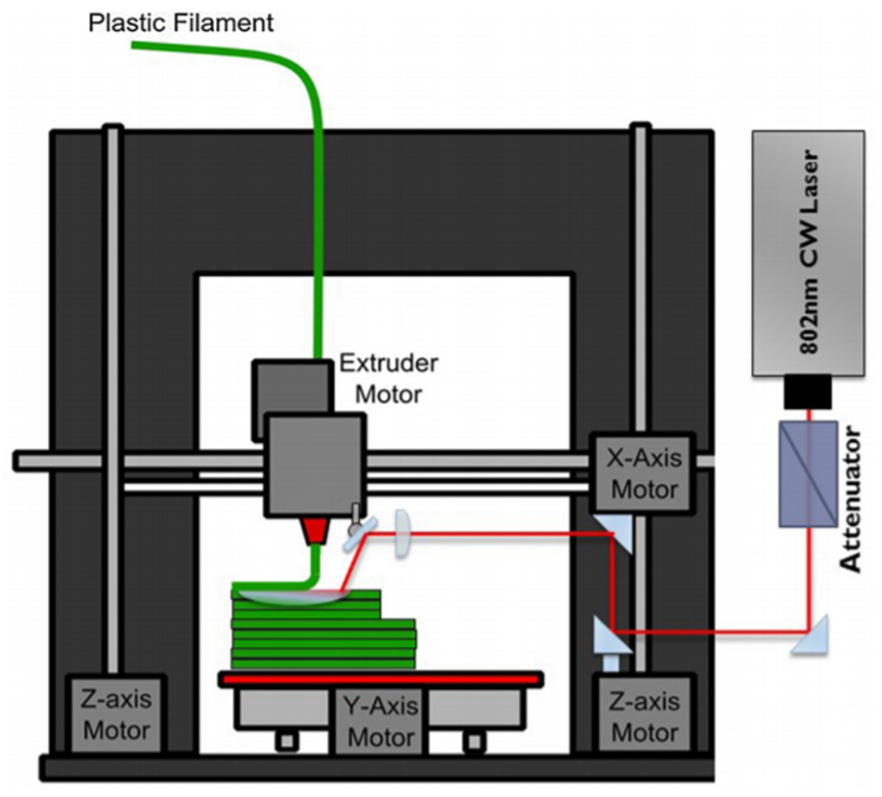
2.3.3. NIR Absorption Measurement for Additive Selection

A photometer was used to measure the light transmission of the extruded filaments. The filament with the additive that gives the lowest value will be selected since the lower the light transmission is, the higher is the light absorption.
Since the laser selected for localized heating operates with the NIR spectrum, the wavelength range which was of concern was the NIR range taken between 825 nm and 912.5 nm as this complements the operating range of the selected diode laser. Therefore, intensity curves were plotted, as shown in Figure 9 and Figure 10 for PLA and ABS, respectively, to show how the extruded filament absorb light within the NIR spectrum.
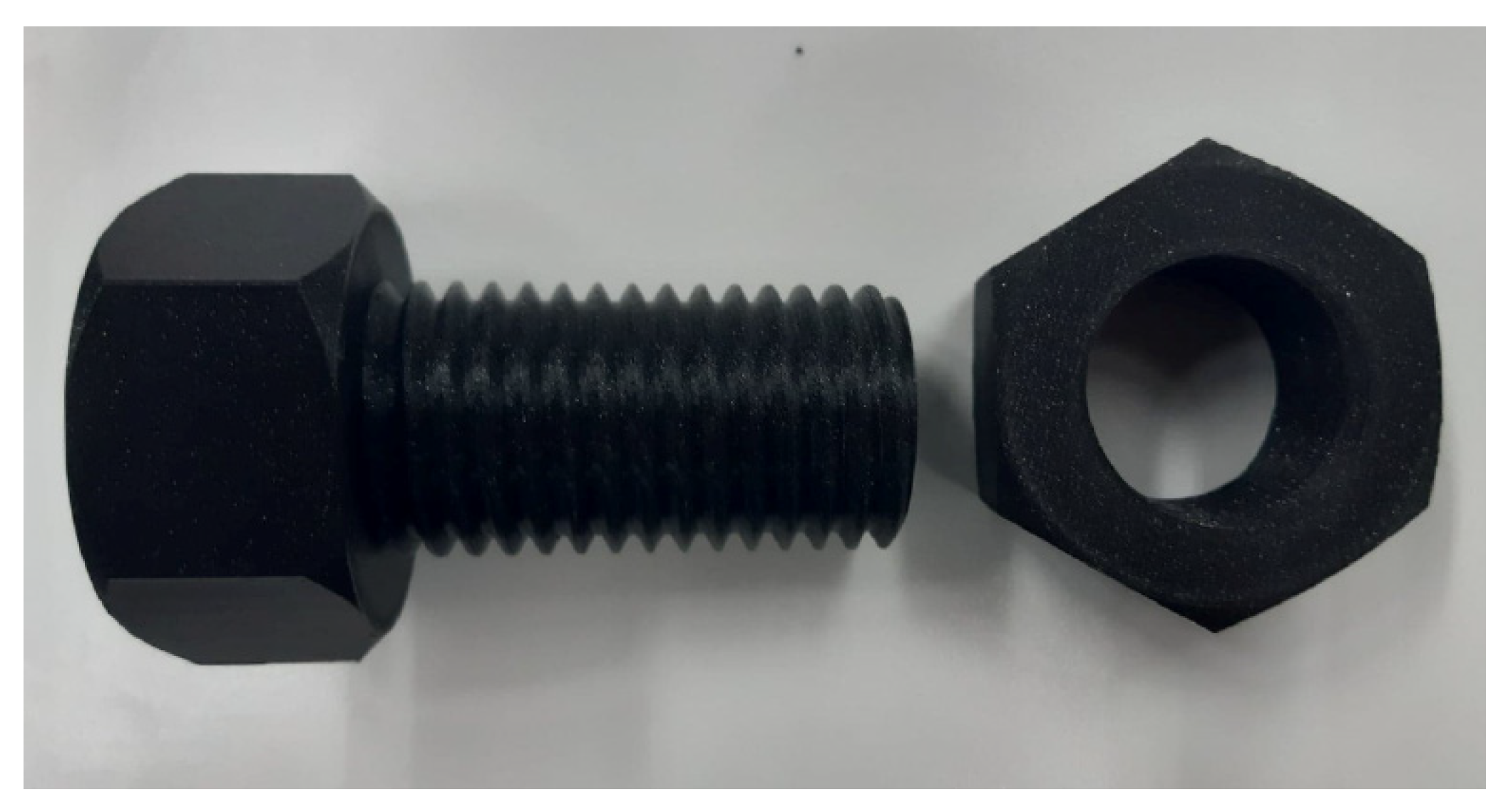
Graphite and CNT achieved the best NIR absorption for both PLA and ABS. Graphite was selected for further filament extrusion as it is exponentially cheaper and results in a consistent filaments’ diameter than CNT whilst having similar NIR absorption properties. Hence, PLA and ABS with 2% graphite filaments would be used for FFF 3D printing of testing specimen.

3. FFF 3D Printing Experiments

3.1. Filament Printability Test

Prior to the experiments using the laser assisted 3D printer, the filaments needed to be tested using a conventional FFF 3D printer. In this paper, the conventional FFF 3D printer refers to 3D printer without laser heating, or in other words, not equipped with laser diode. These experiments were conducted to determine the printability of the extruded filaments. The printer which was selected for conventional FFF 3D printing was the Prusa I3 MK3S printer, developed by Josef Prusa.
The default parameters of Prusa I3 MK3S printer were used to print a case study part using the extruded filaments made from the selected PLA and ABS based composites. These are 0.4 mm nozzle diameter, 15% infill, 0.2 mm layer thickness, 40 mm/s perimeter printing speed as well as monotonic pattern for top/bottom layers and gyroid pattern for the infill. After carefully analyzing and testing different printing parameters, the bed temperature of 60 °C and nozzle temperature of 215 °C were found to be the most optimum parameters for PLA filaments. On the other hand, the most optimal bed temperature for ABS to ensure sufficient bonding between the printing bed and the initial printed layer was at 100 °C, whereas the nozzle temperature to effectively print using ABS material was found to be 255 °C.
As an example for the printability results, the parts seen in Figure 11 were printed using ABS + 2% Graphite filament and the final parts portrayed excellent part quality and the layer bonding was visually exceptional. The additives did not seem to have significant effect on the printability of the filaments.

3.2. Conventional FFF 3D Printing

Using the same conventional Prusa I3 MK3S printer and printing parameters above, testing specimens were printed using different types of filament combinations in order to analyze analytically their material properties.
The CAD part for the tensile specimen was modelled according to ATSM D638 IV standard. The reason behind these tensile tests is to ensure adequate printability of all filaments. However, these tensile tests will also indicate how the material properties will be affected due to the additives and the printing infill. These tensile specimens were printed with PLA + 2% graphite at 25% and 80% printing infill percentages and similarly with ABS + 2% graphite at 25% and 80% printing infill. The infill pattern for the 3D prints was kept constant, namely gyroid structure, with the aim of increasing mechanical properties while reducing part weight. As can be seen in Figure 12, the quality of the printed tensile specimens was exceptional thanks to process parameter optimization. Both PLA and ABS based printed parts had excellent surface finish and from visual inspection, no printing defects were evident.

3.3. Laser Assisted FFF 3D Printing

After being satisfied with the printability of the developed filament, focus shifted on testing whether localized laser heating will directly improve the inter-layer bonding strength between printed layers. For these printing experiments, the Wanhao Duplicator i3 printer was selected and modified. The setup, which can be seen in Figure 13, consisted of a small diode laser, to heat up the previously extruded layer prior to printing the next layer, which was powered by an external power supply. The selected laser mechanism to perform the heating process was a non-wavelength stabilized fiber coupled diode laser, specifically, the M915±10-20-F105/22-T2.
Since the printing of ABS filaments using this printer was not successful yet due to printer’s limitation, as well as due to time restraints, the laser assisted FFF 3D printing experiments were only carried out on PLA + 2% graphite filaments.
To determine the effect of laser heating on the layer-interface’s thermomechanical behavior, lap shear specimen was designed and printed. Since the shear experiments were carried out on the DMA machine in tension mode, the lap shear specimen was designed with alignment tabs so that the center of the bonding interface coincides with the center of the applied force as can be seen in Figure 14. During the printing process of the lap shear specimens, support structures were incorporated to ensure that the layers were as smooth as possible.
Figure 15 shows the shear testing specimens that were printed with the same orientation and part dimension as mentioned in the previous section. There were three main differences with regards to printing parameters; the printer’s bed temperature was lowered to 50 °C, the nozzle temperature lowered to 210 °C and the percentage infill was increased to 100% in order to ensure successful localized laser heating of the previously extruded layer.
For tensile specimens, the printing orientation was changed to vertical direction to be able to determine their interlayer bonding strength using tensile testing with and without laser heating. The default parameters were also to be modified by changing the gcode manually. This was necessary due to the vertical printing direction and since the specimen’s cross-sectional area is relatively small (as well as the laser heating, which was carried out only on one side using one laser, as can be seen in Figure 16). The infill was 100% and a layer was made from filament lines placed next to each other. The printing direction was only toward the laser heating source to be able to utilize the maximum laser pre-heating effect. The bed and nozzle temperature were kept the same as for the shear specimen, namely 50 °C and 210 °C, respectively.
The visual quality of the laser assisted FFF 3D printed tensile specimens left a lot to be desired as there were plenty of evident printing defects. This visual quality issue could also be related to the vertical printing orientation of such a slender specimen. Figure 17 shows surface fractures due to the laser pre-deposition heating. These tears on the surface fracture indicate that the inter-layer interfaces within the part have been eliminated and hence, a stronger inter-layer bond is expected [6,24].
The diode laser which was employed to heat the localized spot on the printed layer lacked optimization with regards to wavelength and heating time. These specimens were printed perpendicular to the printer’s bed and this orientation resulted in severe instability especially when printing the elevated ends of the tensile specimen. This instability is expected to be a weak point when the specimens are subjected to tensile testing.

3.4. Testing and Characterization of Printed Specimen

3.4.1. Tensile Testing

Firstly, tensile tests were conducted on specimens conventionally printed with PLA and ABS with 2% graphite at infills of 25% and 80%. Their respective average results were tabulated in Table 7. It was evident that the graphite additive directly increased the elastic modulus and tensile strength. Comparably, when the infill percentage was increased, all of the mentioned material properties also increased. Therefore, it can be concluded that both the infill percentage as well as the graphite additives had significant positive impact on the material properties. The relatively low standard deviation values also showed the excellent printability of the filaments.
From Table 7 and Figure 18a,b, in the case of specimens printed without laser heating, it can be observed that PLA specimens show brittle fracture, while the ABS specimens exhibit ductile fracture. The latter can be confirmed by the whitening and slight necking of the ABS specimens. Generally, the added 2% graphite and the increase in the infill percentage lead to a higher elastic modulus, tensile strength, and strain at break, except the elastic modulus of PLA with 25% infill. This shows that, even without laser heating, the 2% graphite has already a contribution in increasing the mechanical properties of the specimens.
Secondly, tensile testing was also carried out on the laser assisted printed specimens using the same method. It is worth mentioning again that the printing orientation was upright with regards to the printing bed. Thus, it is extremely important to mention that results shown in Table 7 and Table 8 are not to be compared with one another since these results are obtained using different printers, printing orientations and printing processing parameters.
These tests were only carried out using PLA + 2% graphite filaments which were printed using the Wanhoa Duplicator equipped with the laser diode. Two types of specimens were printed, namely with laser heating ON and OFF. The tensile testing results can be seen in Table 8, while Figure 18c represents one of the tested specimens and shows the same brittle fracture of other PLA specimens.
From Table 8, it can be observed that the elastic modulus increased by approximately 14.5% and the tensile strength increased by approximately 27.8%. This clearly suggests that the NIR laser heating was successful in increasing overall strength.

3.4.2. Shear Testing

As described in the previous section, the lab shear specimens were printed from PLA + 2% graphite using the Wanhoa Duplicator equipped with the laser diode. As for filaments, the lap shear specimens were tested in tension mode with a displacement of 10 µm and a frequency of 1 Hz, starting from temperature of 20 °C up to a temperature of 150 °C with a heating rate of 2 K/minute. For comparison purposes, the elastic modulus at 20 °C and 50 °C was read and listed in Table 9.
As expected, the shear stress notably increased when shear specimens were printed using laser heating. The shear stress increased by approximately 22.1% at a temperature of 20 °C and by approximately 21.1% at a temperature of 50 °C. These results further support the fact that laser heating directly increase the interlayer bonding strength of 3D printed parts.

3.4.3. DSC Characterization

The DSC was used for material characterization on the FFF 3D printed parts. The expected differences in results were due to the fact that the samples from the 3D printed parts were subjected to an additional thermal cycle during the printing process when compared with the extruded filaments.
Characterization of the PLA + 2% graphite printed parts was carried out on samples which were printed with and without laser heating to monitor the effects of the laser heating.
As can be seen in Table 10, the crystallinity degree for printed parts was higher than that of the filaments as listed in Table 6. This is mainly due to the fact that during printing, the polymer material is subjected to an additional heating cycle. Similarly, the laser heated parts exhibited the highest crystallization degree from all the filaments and printed parts which were characterized using the DSC for both the first and second heating. This is further supported by the fact that during DSC characterization, the melting enthalpy was the highest during the first heating of the laser assisted printed specimen, since more energy was required to generate the phase change where the molecules change from crystals to amorphous.

4. Discussion and Conclusions

The main problem which was faced during the filament making was the lack of filament diameter consistency especially when CNT is used as the additive. This was assumed due to the continuous change in melt viscosity resulted from the inhomogeneous distribution or agglomeration of the CNT particles in the polymer melt. The use of mixing elements on the screw tip of the filament maker could help the mixing and distribution of the CNT particles.
The most cost-effective graphite showed the best NIR absorption and consistency in the filaments’ diameter. Thus, in contrast to CNT, graphite particles seem easier to be dispersed in the polymer melt. Due to their consistent diameter, the extruded ABS and PLA filaments with 2% graphite could be printed with a high accuracy and repeatability. Both filament types portrayed excellent part quality and the layer bonding was visually exceptional when printed using conventional 3D printer without laser heating. Adding the 2% graphite seems to have no adverse effect on the printability of the filaments, but it increased slightly the specimens’ mechanical properties. The 3D printed specimen of PLA showed a higher degree of crystallinity since the 3D printed specimens are subjected to an additional thermal cycle during the printing process when compared with the extruded filaments. Due to the absence of crystallites in ABS, it was not tested using DSC.
The laser assisted FFF 3D printing experiments were carried out using PLA + 2% graphite filaments since the laser assisted 3D printing of ABS filaments was not successful yet. As expected, with the laser heating and the addition of additive into the filaments, an increase in the crystallinity degree of 14.7% was observed. This shows that the laser heating delays the solidification of polymer, which promote the macromolecules diffusion between two deposited layers. In addition, the polymer melt has also more time to crystallize. Both contribute to strengthening the interlayer bond so that an increase of 14.5% in the elastic modulus and an increase of 27.8% in the tensile strength of the printed parts were noticed. The shear stress also increased by approximately 22% at a temperature of 20 °C and by approximately 21% at a temperature of 50 °C.
In conclusion, laser heating in conjunction with the use of suitable polymer additives is an effective method to increase the inter-layer bonding strength. However, further comprehensive research needs to be conducted to attain quasi-isotropic mechanical properties such in injection molded parts. By finding a way to significantly increase the inter-layer bonding strength, and therefore the strength and durability of the printed part, the 3D printing technology can be adopted by various sectors as the main drawback of FFF 3D printing is diminished.

Author Contributions

Filament development, conventional 3D printing G.B.; characterization of filaments and 3D printed specimens including results analysis, G.B. and A.R.; laser assisted printing head, laser absorption test, laser assisted 3D printing, S.K.; funding acquisition, project management, S.K. and A.R. All authors have read and agreed to the published version of the manuscript.

Funding

This research project, titled Development of 3D Printing Head with Laser Melting for Printers Using Fused Filament Fabrication (FFF) Technology (LASeeeR), was funded by the Malta Council for Science and Technology (MCST) through its FUSION RI Technology Development Programme, with the grant number RI-2017-025T.

Acknowledgments

We thank all researchers at our local industrial partner (Laser Engineering Development Limited) for their support in laser engineering field and for providing the laser assisted 3D printer.

Conflicts of Interest

The authors declare no conflict of interest.

Abbreviations

The following abbreviations are used in this manuscript.
FFFFused Filament Fabrication
DSCDifferential Scanning Calorimetry
DMADynamic Mechanical Analysis
CNTCarbon Nanotubes
NIRNear Infrared
ABSAcrylonitrile Butadiene Styrene
PLAPolylactic Acid
RPMRevolutions per Minute

References

  1. Chartier, T.; Badev, A. Chapter 6.5-rapid prototyping of ceramics. In Handbook of Advanced Ceramics, 2nd ed.; Somiya, S., Ed.; Academic Press: Oxford, UK, 2013; pp. 489–524. ISBN 978-0-12-385469-8. [Google Scholar]
  2. Wong, K.V.; Hernandez, A. A review of additive manufacturing. Int. Sch. Res. Not. 2012, 2012, 20876. [Google Scholar] [CrossRef] [Green Version]
  3. Manufacturing, M.T. Benefits and Disadvantages to 3D Printing in Manufacturing. Available online: https://www.mh-mfg.com/resource/benefits-and-drawbacks-to-3d-printing-in-manufacturing/ (accessed on 19 June 2018).
  4. Schirmeister, C.G.; Hees, T.; Licht, E.H.; Muelhaupt, R. 3D printing of high density polyethylene by fused filament fabrication. Addit. Manuf. 2019, 28, 152–159. [Google Scholar] [CrossRef]
  5. Varotsis, A.B. Introduction to FDM 3D Printing Beginners. Available online: https://www.hubs.com/knowledge-base/introduction-fdm-3d-printing/ (accessed on 28 December 2020).
  6. Han, P.; Tofangchi, A.; Deshpande, A.; Zhang, S.; Hsu, K. An approach to improve interface healing in FFF-3D Printed ULTEM 1010 using laser pre-deposition heating. Procedia Manuf. 2019, 34, 672–677. [Google Scholar] [CrossRef]
  7. Ravi, A.K.; Deshpande, A.; Hsu, K.H. An in-process laser localized pre-deposition heating approach to inter-layer bond strengthening in extrusion based polymer additive manufacturing. J. Manuf. Process. 2016, 24, 179–185. [Google Scholar] [CrossRef]
  8. Ahn, S.-H.; Montero, M.; Odell, D.; Roundy, S.; Wright, P.K. Anisotropic material properties of fused deposition modeling ABS. Rapid Prototyp. J. 2002, 8, 248–257. [Google Scholar] [CrossRef] [Green Version]
  9. Omnexus. Polylactic Acid or Polylactide, PLA Plastic, Lactic Acid Polymer Guide. Available online: https://omnexus.specialchem.com/selection-guide/polylactide-pla-bioplastic (accessed on 29 November 2020).
  10. Garlotta, D. A literature review of poly (lactic acid). J. Polym. Environ. 2001, 9, 63–84. [Google Scholar] [CrossRef]
  11. Ingeo™ Biopolymer 4043D Technical Data Sheet. Available online: https://www.natureworksllc.com/~/media/Files/NatureWorks/Technical-Documents/Technical-Data-Sheets/TechnicalDataSheet_4043D_3D-monofilament_pdf.pdf (accessed on 4 November 2020).
  12. MAGNUMTM 3453 ABS Resin. Available online: https://catalog.ulprospector.com/docselect.aspx?I=11770&E=57033&DOC=DOWTDSEN&DS=432&DK=STD&DC=en (accessed on 6 January 2021).
  13. Near Infra-Red (NIR) Dyes Pigments for Anti-Counterfeit Solutions. Available online: https://luminochem.com/nir-absorbing-pigments (accessed on 19 October 2020).
  14. Smausz, T.; Kondász, B.; Gera, T.; Ajtai, T.; Utry, N.; Pintér, M.; Kiss-Albert, G.; Budai, J.; Bozóki, Z.; Szabó, G.; et al. Determination of UV–Visible–NIR absorption coefficient of graphite bulk using direct and indirect methods. Appl. Phys. A 2017, 123, 1–7. [Google Scholar] [CrossRef]
  15. Norindr, F. Study of Inorganic Transparent Materials with Near-Infrared Absorbing Properties. Ph.D. Thesis, University of Southampton, Southampton, UK, 2009. [Google Scholar]
  16. Weisman, R.B.; Subramoney, S. Carbon Nanotubes. Electrochem. Soc. Interface 2006, 15, 42. [Google Scholar] [CrossRef]
  17. Meet the Composer and Precision-Desktop Filament Makers. Available online: https://3devo.com/filament-makers/ (accessed on 7 February 2021).
  18. Filament Extruder—3devo. Available online: https://3devo.com/filament-extruder/ (accessed on 7 February 2021).
  19. Dey, A.; Yodo, N. A systematic survey of FDM process parameter optimization and their influence on part characteristics. J. Manuf. Mater. Process. 2019, 3, 64. [Google Scholar] [CrossRef] [Green Version]
  20. Magdum, Y.; Pandey, D.; Bankar, A.; Harshe, S.; Parab, V.; Kadam, M. Process parameter optimization for FDM 3D printer. Int. Res. J. Eng. Technol. (IRJET) 2019, 6, 1–6. [Google Scholar]
  21. Spoerk, M.; Gonzalez-Gutierrez, J.; Sapkota, J.; Schuschnigg, S.; Holzer, C. Effect of the printing bed temperature on the adhesion of parts produced by fused filament fabrication. Plast. Rubber Compos. 2018, 47, 17–24. [Google Scholar] [CrossRef]
  22. Omnexus. Glass Transition Temperature (Tg) of Plastics-Definition Values. Available online: https://omnexus.specialchem.com/polymer-properties/properties/glass-transition-temperature (accessed on 27 April 2021).
  23. Fischer, E.W.; Sterzel, H.J.; Wegner, G. Investigation of the structure of solution grown crystals of lactide copolymers by means of chemical reactions. Kolloid-Z. Z. Polym. 1973, 251, 980–990. [Google Scholar] [CrossRef]
  24. Günaydın, K.; Türkmen, H.S. Common FDM 3D printing defects. In Proceedings of the International Congress on 3D Printing (Additive Manufacturing) Technologies and Digital Industry, Antalya, Turkey, 19–21 April 2018. [Google Scholar]
Figure 1. FFF printing using pre-deposition laser heating [7].
Jmmp 05 00115 g001
Figure 2. Filament Maker—Composer 450 [17].
Jmmp 05 00115 g002
Figure 3. Filament development of PLA with additives.
Jmmp 05 00115 g003
Figure 4. Filament development of ABS with additives.
Jmmp 05 00115 g004
Figure 5. DMA result of PLA based filaments.
Jmmp 05 00115 g005
Figure 6. DMA results of ABS based Filaments.
Jmmp 05 00115 g006
Figure 7. DMA results of ABS and ABS 2% graphite filaments.
Jmmp 05 00115 g007
Figure 8. DSC curve of PLA + 2% graphite filament.
Jmmp 05 00115 g008
Figure 9. Light transmission of PLA filaments with different additives.
Jmmp 05 00115 g009
Figure 10. Light transmission of ABS filaments with different additives.
Jmmp 05 00115 g010
Figure 11. Parts printed with ABS + 2% Graphite filament.
Jmmp 05 00115 g011
Figure 12. ABS tensile specimen during printing (a) and printed PLA tensile specimen (b), both with 2% graphite and an infill of 80%.
Jmmp 05 00115 g012
Figure 13. Setup for the Laser Assisted FFF 3D Printer.
Jmmp 05 00115 g013
Figure 14. CAD model of lap shear specimen.
Jmmp 05 00115 g014
Figure 15. Shear specimens printed using PLA + 2% graphite.
Jmmp 05 00115 g015
Figure 16. Fixed position of laser heating source relative to the nozzle.
Jmmp 05 00115 g016
Figure 17. Laser assisted FFF printed tensile specimen.
Jmmp 05 00115 g017
Figure 18. Tensile tested specimen: (a) PLA and (b) ABS both with 2% graphite and infill of 80% printed using the PRUSA I3 MK3S printer without laser heating, and (c) PLA + 2% graphite printed using the Wanhoa Duplicator equipped with the laser diode.
Jmmp 05 00115 g018
Table 1. Properties of the selected materials [11,12].
Material PropertiesPLA 4043DABS 3453
Melting temperature Tm (°C)145–160amorphous, no true (Tm)
Glass transition temperature Tg (°C)55–6095–105
Heat distortion temperature (°C) 55100
Tensile modulus (GPa)3.602.28
Tensile yield strength (MPa)6048
Tensile strength at break (MPa) 5342
Flexural stress (MPa)8365
Table 2. A comparison on price for different additives.
AdditivePrice (€)/g
Graphite0.10
Carbon Nanotubes70.00
Luniri1®15.00
Table 3. Processing parameters during PLA filament extrusion.
FilamentTemperature (°C)Screw Speed (RPM)Cooling Speed (%)
H4H3H2H1
Raw PLA1701851901703.570
PLA + 1% Graphite1701851901703.570
PLA + 2% Graphite1701851901703.570
PLA + 1% CNT1701851901704.270
PLA + 2% CNT1701851901704.570
PLA + 1% Luniri1®1701851901703.870
PLA + 2% Luniri1®1701851901704.070
Table 4. Processing parameters during ABS filament extrusion.
FilamentTemperature (°C)Screw Speed (RPM)Cooling Speed (%)
H4H3H2H1
Raw ABS2202352402203.560
ABS + 1% Graphite2202352402203.760
ABS + 2% Graphite2202352402204.560
ABS + 1% CNT2202352402203.960
ABS + 2% CNT2202352402204.760
ABS + 1% Luniri1®2202352402203.660
ABS + 2% Luniri1®2202352402204.360
Table 5. DSC results of PLA based filaments.
FilamentHeatingGlass TransitionCrystallizationMelting
Tg (°C)ΔHg (J/g)Tc (°C)ΔHcc (J/g)Tm (°C)ΔHm (J/g)
Raw PLAFirst58.762.42117.43−4.33151.1317.58
Second62.901.14122.10−3.70150.9912.82
PLA + 1% GraphiteFirst60.052.84120.73−2.76152.7314.65
Second63.071.61126.05−1.31152.305.44
PLA + 2% GraphiteFirst59.573.19119.42−2.97151.4613.15
Second62.990.25126.41−0.95152.024.08
PLA + 1% CNTFirst62.362.46119.74−10.17153.1518.09
Second63.051.15122.74−7.60152.0016.44
PLA + 2% CNTFirst59.021.51115.40−9.37151.8115.96
Second62.060.58122.74−4.02152.4813.76
PLA + 1% Luniri1®First58.522.18118.04−5.15153.1614.10
Second63.041.00127.35−1.08152.746.05
PLA + 2% Luniri1®First58.071.85118.75−4.19152.2415.00
Second62.741.27127.23−2.33152.137.27
Table 6. The degree of crystallinity for different filaments.
FilamentHeatingDegree of Crystallinity (%)
Raw PLAfirst18.9
second13.8
PLA + 1% GraphiteFirst15.8
Second5.8
PLA + 2% GraphiteFirst14.1
Second4.4
PLA + 1% CNTFirst19.5
Second17.7
PLA + 2% CNTFirst17.2
Second14.8
PLA + 1% Luniri1®First15.2
second6.5
PLA + 2% Luniri1®First16.1
Second7.8
Table 7. Tensile results to assess filaments’ printability using the PRUSA I3 MK3S printer without laser heating.
FilamentInfill (%)Elastic Modulus (GPa)Tensile Strength (MPa)Strain at Break (%)
PLA Raw252.08 ± 0.2226.86 ± 0.521.75 ± 0.35
802.16 ± 0.1733.25 ± 0.924.43 ± 1.37
PLA + 2% Graphite251.82 ± 0.1230.42 ± 0.543.13 ± 0.32
802.43 ± 0.1536.60 ± 0.415.00 ± 0.85
ABS Raw251.60 ± 0.1225.25 ± 0.532.47 ± 0.55
801.86 ± 0.1131.66 ± 0.409.57 ± 3.07
ABS + 2% Graphite251.63 ± 0.1026.34 ± 0.133.38 ± 1.73
801.97 ± 0.0332.52 ± 0.3210.06 ± 5.05
Table 8. Effect of laser heating during printing on the tensile properties of PLA + 2% graphite specimens.
Laser HeatingElastic Modulus (GPa)Tensile Strength (MPa)Strain at Break (%)
ON1.34 ± 0.2326.75 ± 0.481.53 ± 0.80
OFF1.17 ± 0.0520.93 ± 0.712.60 ± 0.36
Table 9. Effect of laser heating during printing on shear stress of PLA + 2% graphite specimens.
Laser HeatingShear Stress (MPa)
at 20 °Cat 50 °C
ON9486
OFF7771
Table 10. Effect of laser heating during printing on crystallinity degree of PLA + 2% graphite specimens.
Laser HeatingDSC HeatingDegree of Crystallinity (%)
ONfirst25.0
second18.9
OFFfirst21.8
second16.1
Publisher’s Note: MDPI stays neutral with regard to jurisdictional claims in published maps and institutional affiliations.

