Fabrication of Piezoelectric Composites Using High-Temperature Dielectrophoresis


1
Department of Mechanical and Construction Engineering, Faculty of Engineering and Environment, Northumbria University, Newcastle Upon Tyne NE1 8ST, UK
2
Novel Aerospace Materials Group, Faculty of Aerospace Engineering, Delft University of Technology, Kluyverweg 1, 2629 HS Delft, The Netherlands
3
SABIC Corporate Research & Development, Plasticslaan 1, 4612 PX Bergen op Zoom, The Netherlands
4
Holst Centre, TNO, High Tech Campus 31, 5605 KN Eindhoven, The Netherlands
*
Author to whom correspondence should be addressed.
J. Manuf. Mater. Process. 2019, 3(3), 77; https://doi.org/10.3390/jmmp3030077
Submission received: 13 August 2019
/
Revised: 28 August 2019
/
Accepted: 30 August 2019
/
Published: 2 September 2019
Abstract
:In this paper, we present a method to create a highly sensitive piezoelectric quasi 1–3 composite using a thermoplastic material filled with a piezoelectric powder. An up-scalable high-temperature dielectrophoresis (DEP) process is used to manufacture the quasi 1–3 piezoelectric polymer-ceramic composites. For this work, thermoplastic cyclic butylene terephthalate (CBT) is used as a polymer matrix and PZT (lead zirconium titanate) ceramic powder is chosen as the piezoelectric active filler material. At high temperatures, the polymer is melted to provide a liquid medium to align the piezoelectric particles using the DEP process inside the molten matrix. The resulting distribution of aligned particles is frozen upon cooling the composite down to room temperature in as little as 10 min. A maximum piezoelectric voltage sensitivity (g33) value of 54 ± 4 mV·m/N is reported for the composite with 10 vol% PZT, which is twice the value calculated for PZT based ceramics.
1. Introduction
Piezoelectric ceramics such as lead zirconium titanate (PZT) have been researchers’ preferred choice in sensing and actuation applications, owing to their low cost and high piezoelectric performance, compared to their counterparts [1,2,3]. Although PZT (and piezoelectric ceramics in general) have the aforementioned advantages, they are too brittle to be integrated into flexible devices. As the scope of sensors is shifting towards flexible and portable electronics, self-powered [4,5,6] and lightweight sensors [7] have to be developed with flexibility as an added feature. For flexible piezoelectric materials, polyvinylidene difluoride (PVDF)-based piezoelectric polymers offer relatively high dielectric constant values compared to other polymers, which results in superior piezoelectric properties. However, manufacturing of PVDF based sensors is an expensive process, which, in turn, demands alternative inexpensive material options.
Another candidate for flexible sensors is piezoelectric composite, in which piezoelectrically active ceramics nano/micro particles are embedded inside an inactive polymer matrix [8,9]. The orientation of particles inside composites is generally random, and these kinds of composites are referred to as 0–3 composites where the first and second integer designates filler and matrix connectivity, respectively. The manufacturing of said composites is not challenging and does not require intricate technology. However, in order to increase the sensitivity of these composites, higher weight/volume ratios of active filler within the matrix are required, however, that compromises flexibility of the composite [10]. This is due to the fact that the poling field in 0–3 composites is generally concentrated around the polymer and not over the random ceramic particles. Hence, a higher percentage of filler is required to observe a higher poling field.
On the other hand, it has been demonstrated that aligning ceramic particles inside the polymer matrix using dielectrophoresis (DEP) (composites designated as quasi 1–3) enhances the piezoelectric voltage coefficient (g33) significantly compared to the composites with a random orientation of the particles [3]. This is due to the fact that the inter-particle distance between the filler particles is reduced, which increases poling efficiency, resulting in higher g33 values at low volume fractions of fillers (~5–10%) [11]. Values of as high as 103 mV·m/N have been reported for various epoxy-based composites, which is much higher than the values reported for ceramics [12,13,14]. This proves DEP is an effective technique to manufacture piezoelectric composites that also helps to reduce material costs and implies a conservation of the flexibility and failure strain of the composites at a level close to that of the polymeric matrix. DEP alignment of particles depends upon the combination of viscosity of the polymer matrix, the density of the filler, and the applied alternating current (AC) field [15]. During the alignment process, particles experience a DEP force that helps them to move inside the polymer matrix [16]. As a result of the DEP force, particles (fillers) exert a drag force on the matrix, which depends upon the viscosity and density of the particles [17]. Most of the research on the dielectrophoretic alignment of particles inside polymer matrices has been limited to thermosetting polymers such as polydimethylsiloxane (PDMS) and epoxy [1,18], due to their ease of processing and suitable viscosity for DEP processing [10]. However, only certain types of thermosetting matrices with longer curing times can be used as the curing times plays a vital role in decreasing the viscosity of thermosets, which results in the low degree of alignment. On top of that, the curing of thermosets is an additional step that increases the processing time. Curing can be carried out at room temperature or it can be accelerated using heat or UV curing [4]; these techniques obviously can alter the inherent properties of the matrix [7] and are not always beneficial. There have been very few reports of the use of a thermoplastic matrix for particle alignment using a solvent to decrease matrix viscosity [17,19]. This process, however, is intricate and time consuming as the complete removal of solvent is desired to get optimum piezoelectric properties.
Cyclic butylene terephthalate (CBT) is an oligomer that polymerizes very quickly into polymerized CBT (pCBT) during subsequent cooling. One of the striking benefits of CBT is its water-like viscosity [20], which not only helps to improve the manufacturing possibilities but also improves the dispersion and interface when fillers are added for composite making [21]. Due to its comparable mechanical properties to epoxy, CBT has the potential to substitute thermosets and can solve the recycling issues of thermosetting matrices [22].
In this paper, aligned piezoelectric composite sensors are fabricated using a thermoplastic matrix with the high-temperature dielectrophoresis method. CBT (cyclic butylene terephthalate) is chosen as a polymer matrix owing to its low viscosity of only 20 cps at temperatures just above the melting point [20] and quick processing. Both these properties (time and viscosity) are crucial in the alignment of particles during DEP processing.
2. Materials and Methods
CBT®160 pellets (cyclic butylene terephthalate (CBT) supplied by the Cyclics Corporation and lead zirconate titanate powder (PZ 26) provided by Ferroperm (Humlebaek, Denmark) were used as ceramic filler. CBT is a low-molecular-weight oligomer that melts in the range of 130–150 °C. The initial viscosity of CBT is ~20 cps, which is expected to increase during polymerization, yielding pCBT (poly cyclic butylene terephthalate) [23]. CBT powder with different ratios of ceramic filler (5–20 vol%) were mixed using roll milling, and pellets of 15 mm diameter were made using a cold press under 5 tonnes of force.
The unconsolidated pellets were placed inside a mold made up of 1 mm thick Teflon sheet having cut outs of 15 mm in diameter. The Teflon sheet was sandwiched between two aluminum sheets (50 μm thick) that served as a top and bottom electrode. The whole assembly was covered with an alumina plate and placed on top of a heater (Bach Resistor Ceramics GmbH, Werneuchen, Germany) fitted with a temperature controller, as depicted in Figure 1a.
Paper clips were used to hold everything together and to apply a semi-constant pressure, as shown in Figure 1b. The complete assembly, together with the amplifier and function generator, is shown in Figure 1c. In order to align the particles inside the molten polymer, an electric field of 2 kV/mm at a frequency of 1 kHz was chosen [9,18]. AC electric field was applied at room temperature using a function generator linked to a high voltage amplifier. The reason for applying voltage at room temperature was to make sure sedimentation did not take place when the polymer started to melt due to its relatively low viscosity compared to epoxy. The mixture of CBT and the ceramic particles was heated to 235 °C at a rate of 400 °C/min, and the mixture was consequently held at this temperature for 3 min in order to ensure the complete polymerization of CBT to pCBT (poly cyclic butylene terephthalate) and alignment of ceramic particles. After 3 min, the heater was turned off and the mold was allowed to cool down naturally while applying the electric field. Once a temperature of 160 °C was reached, the field was removed and the mold was quenched in water at room temperature.
Dielectrophoretically structured composite discs were polished to remove the top and bottom layers and sputtered with gold on both sides using Q300T (Quorum, Laughton, UK) to create the electrodes. Following sputtering, the composite samples were poled at 100 °C under a DC field of 10 kV/mm in a water-cooled oil bath SE Class III (Julabo, Seelbach, Germany) in silicone oil for half an hour [1]. The electric field was removed once the samples were cooled down to room temperature. Cross sections of the samples were examined using a JSM-7500F SEM (Jeol, Tokypo, Japan). The relative dielectric constant (r) was measured using a parallel plate capacitor method with an 4263B (Agilent, Santa Clara, CA, USA) LCR meter at a voltage of 1 V and a frequency of 1 kHz, and the piezoelectric charge coefficient (d33) was measured using a PM300 d33 PiezoMeter System, (Piezotest, Singapore) [18]. The piezoelectric charge coefficient (g33) was calculated from the values of r and d33 using Equation (1).
where o is the permittivity of vacuum taken as 8.85 × 10⁻¹² F/m.
3. Results and Discussion
Figure 2a shows a differential scanning calorimetry (DSC) curve for CBT oligomers. The melting of CBT took place between 105 and 190 °C, which is consistent with previous findings [24]. There are two distinct melting peaks at 140 and 228 °C. The first peak is the melting of CBT, while an exothermic peak around 194 °C appeared before the second melting of CBT, which could have been related to simultaneous crystallization and polymerization of CBT to pCBT [25]. After polymerization of CBT to pCBT, a sharp melting peak at 228 °C was seen in Figure 2b, which represents melting of pCBT. In order to check if all the oligomers have been converted into polymer, a second heating run was imposed. During the second heating run, the pCBT exhibited no endothermic peak, suggesting that all oligomers were converted into to the polymer. As expected, no Tg (glass transition temperature) was observed and the melting peak shifted to a marginally lower temperature of 223 °C, which is in accordance with findings by Wu et al. [26].
Figure 3 shows SEM images of the CBT-PZT composite having 10 vol% of ceramic filler. Information regarding the particle size of the ceramic filler can be found elsewhere [9]. Figure 3a,b demonstrates the sedimentation of PZT in pCBT matrix in the absence of an electric field. Nearly all the particles settle down at the bottom of the sample due to the low initial viscosity of the oligomer and the high density of the PZT (7.86 g/cc). Figure 3c,d shows the alignment of ceramic fillers in the direction of the applied electric field. The alignment of particles yielding chain like structures without obvious macroscopic sedimentation is clearly visible. Agglomeration of particles within the chain like structure was observed, which is a common feature of dielectrophoretically structured composites [3]. Sedimentation could not be found in the structured composites. A magnified image of an area in the cross section of the sample is shown in Figure 3e, indicating perfect alignment of the particles.
Figure 4 shows the piezoelectric properties of the poled pCBT–PZT composites, which are compared with the values as predicted by an analytical model proposed by Van den Ende et al. [3]. The value for the dielectric constant increases continuously with an increasing volume fraction, as shown in Figure 4a. The experimental data match well with the analytical model at lower volume fractions. However, at higher volume fractions, the experimental value was higher than the one predicted by the analytical model. On the other hand, experimental d33 (Figure 4b) values were lower in magnitude than those predicted by the model, which indicates a further optimization of the poling procedure.
The piezoelectric voltage coefficient (g33) values were calculated using Equation (1) and are plotted in Figure 4c. The g33 value initially increased rapidly with increasing PZT vol%, but after reaching its maximum value it dropped slowly with increasing PZT volume fraction. A maximum g33 value of 54 ± 4 mV·m/N at 10 vol% of PZT was achieved, which is twice the values calculated for PZT-based ceramics (25 mV·m/N for PZ 26 and 28 mV·m/N for PZT5A4) [18]. Interestingly, the g33 values predicted by the Van den Ende model matched the values obtained for epoxy–PZT composites, another vital point proving the efficiency of high-temperature DEP technique without sacrificing performance. However, as the experimental d33 values for pCBT–PZT composites were lower than the ones predicted by Van den Ende model, the subsequent g33 values were also lower compared to the predicted values. These values can be matched by optimizing the poling conditions, which demands a comprehensive poling study on pCBT-based composites. Un-poled composites did not show any d33 values and hence did not show any piezoelectric voltage coefficient.
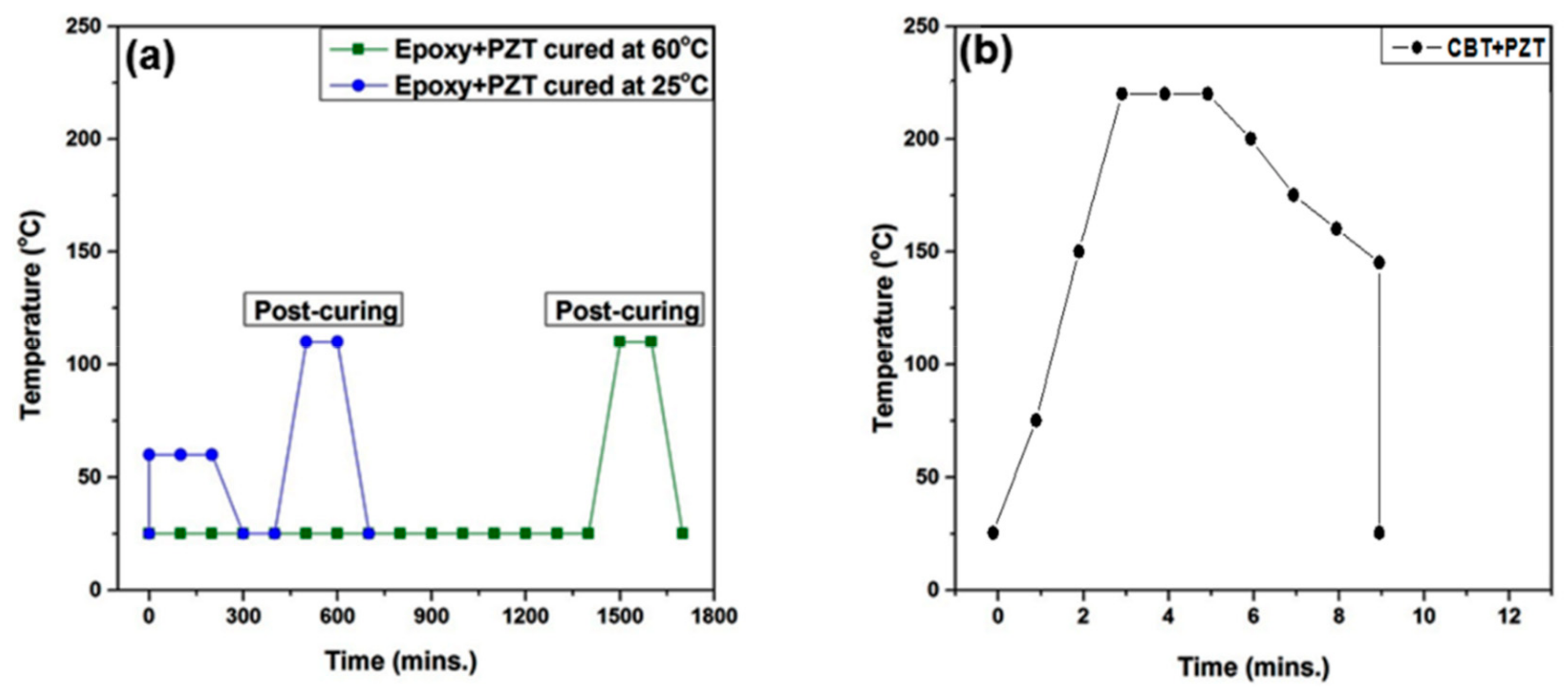
The main advantage of employing the high temperature dielectrophoresis process using a thermoplastic polymer is the relatively short processing time compared to epoxy-based piezoelectric composites. Figure 5 compares the time required to prepare composites using DEP for various systems. For epoxy-based composites, the time of preparation ranges from 5 to 24 h as epoxy needs to be cured in order to have its optimum properties. On the other hand, using the method proposed in this paper (high-temperature DEP), thermoplastic-based composites can be manufactured in as short a time as 10 min.
4. Conclusions
This work demonstrates that ceramic fillers can easily be aligned inside thermoplastic-based matrices using an AC electric field to manufacture composites with piezoelectric activity. A g33 value of 54 ± 4 mV·m/N at 10 vol% of PZT was obtained using cyclic butylene terephthalate as the matrix polymer. These results already show the huge potential of making highly sensitive piezoelectric composite sensors using a thermoplastic polymer filled with aligned piezoelectric particles. The high-temperature DEP method not only reduces the manufacturing time, it also increases the recycling opportunities of thermoplastic-based piezoelectric materials compared to thermosetting-based ones.
This method can further be extended to other thermoplastic matrices like polyethylene (PE), polylatic acid (PLA), acrylonitrile butadiene styrene (ABS), and polyether ether ketone (PEEK), together with other fillers such as barium titanate (BT), bismuth sodium titanate (BNT), sodium potassium niobate (KNN), and other piezoelectric ceramics. PLA is of significant importance due to its biocompatibility, cost effectiveness, and ease of use in additive manufacturing. Combining high-temperature DEP with fused deposition modeling (FDM) to align filler particles can enhance the sensitivity of the composites compared to the ones with random orientation of filler. This technique will present new opportunities to integrate sensors using additive manufacturing.
5. Patent
A US Patent Application 16/323,669, 2019 has emerged out of the work.
Author Contributions
Conceptualization, J.K. and P.G.; methodology, validation, formal analysis, data creation, original draft preparation, J.K.; review and editing, J.K, P.G., and T.H.; supervision, P.G. and T.H.; funding acquisition, P.G.
Funding
This research was funded by Saudi Basic Industries Corporation (SABIC).
Conflicts of Interest
The authors declare no conflict of interest.
References
- Deutz, D.B.; Mascarenhas, N.T.; Zwaag, S.; Groen, W.A. Poling piezoelectric (K,Na,Li)NbO3-polydimethylsiloxane composites. Ferroelectrics 2017, 515, 68. [Google Scholar] [CrossRef]
- Khan, M.N.; Jelani, N.; Li, C.; Khaliq, J. Flexible and low cost lead free composites with high dielectric constant. Ceram. Int. 2017, 43, 3923. [Google Scholar] [CrossRef]
- Van den Ende, D.A.; Bory, B.F.; Groen, W.A.; Van der Zwaag, S. Improving the d33 and g33 properties of 0-3 piezoelectric composites by dielectrophoresis. J. Appl. Phys. 2010, 107, 024107. [Google Scholar] [CrossRef]
- Mendes-Felipe, C.; Oliveira, J.; Etxebarria, I.; Vilas-Vilela, J.L.; Lanceros-Mendez, S. State-of-the-Art and Future Challenges of UV Curable Polymer-Based Smart Materials for Printing Technologies. Adv. Mater. Technol. 2019, 4, 1800618. [Google Scholar] [CrossRef]
- Makarovic, M.; Bencan, A.; Walker, J.; Malic, B.; Rojac, T. Processing, piezoelectric and ferroelectric properties of (x) BiFeO3-(1-x) SrTiO3 ceramics. J. Eur. Ceram. Soc. 2019, 39, 3693. [Google Scholar] [CrossRef]
- Lee, T.I.; Jang, W.S.; Lee, E.; Kim, Y.S.; Wang, Z.L.; Baik, H.K.; Myoung, J.M. Ultrathin self-powered artificial skin. Energy Environ. Sci. 2014, 7, 3994. [Google Scholar] [CrossRef]
- Hong, S. Influence of curing conditions on the strength properties of polysulfide polymer concrete. Appl. Sci. 2017, 7, 833. [Google Scholar] [CrossRef]
- Mao, Y.; Zhao, P.; McConohy, G.; Yang, H.; Tong, Y.; Wang, X. Sponge-like piezoelectric polymer films for scalable and integratable nanogenerators and self-powered electronic systems. Adv. Energy Mater. 2014, 4, 1301624. [Google Scholar] [CrossRef]
- Vivekananthan, V.; Alluri, N.R.; Purusothaman, Y.; Chandrasekhar, A.; Kim, S.-J. A flexible, planar energy harvesting device for scavenging road side waste mechanical energy via the synergistic piezoelectric response of K0.5Na0.5NbO3-BaTiO3/PVDF composite films. Nanoscale 2017, 9, 15122. [Google Scholar] [CrossRef]
- Yamada, T.; Ueda, T.; Kitayama, T. Architecture Engineering of Hierarchically Porous Chitosan/Vacuum-Stripped Graphene Scaffold as Bioanode for High Performance Microbial Fuel Cell. J. Appl. Phys. 1982, 53, 4328. [Google Scholar] [CrossRef]
- Khanbareh, H.; Hegde, M.; Bijleveld, J.C.; Zwaag, S.; Groen, P. Functionally graded ferroelectric polyetherimide composites for high temperature sensing. J. Mater. Chem. C 2017, 5, 9389. [Google Scholar] [CrossRef]
- Gao, X.; Zheng, M.; Yan, X.; Fu, J.; Zhu, M.; Hou, Y. The alignment of BCZT particles in PDMS boosts the sensitivity and cycling reliability of a flexible piezoelectric touch sensor. J. Mater. Chem. C 2019, 7, 961. [Google Scholar] [CrossRef]
- Bowen, C.P.; Newnham, R.E.; Randall, C.A. Dielectric properties of dielectrophoretically assembled particulate-polymer composites. J. Mater. Res. 1998, 13, 205. [Google Scholar] [CrossRef]
- Khanbareh, H.; Zwaag, S.; Groen, W.A. Effect of dielectrophoretic structuring on piezoelectric and pyroelectric properties of lead titanate-epoxy composites. Smart Mater. Struct. 2014, 23, 105030. [Google Scholar] [CrossRef]
- Wilson, S.A.; Maistros, G.M.; Whatmore, R.W. Journal of Physics D: Applied Physics Structure modification of 0–3 piezoelectric ceramic/polymer composites through dielectrophoresis. J. Phys. D Appl. Phys. 2005, 38, 175–182. [Google Scholar] [CrossRef]
- Jones, T.B. Dielectrophoretic force calculation. J. Electrost. 1979, 6, 69. [Google Scholar] [CrossRef]
- Choi, K.; Choi, W.; Yu, C.; Park, Y.T. Synthesis of gold nanoparticles dispersed in palm oil using laser ablation technique. J. Nanomater. 2017, 2017, 5. [Google Scholar]
- Khaliq, J.; Deutz, D.B.; Frescas, J.A.C.; Vollenberg, P.; Hoeks, T.; Zwaag, S.; Groen, P. Effect of the piezoelectric ceramic filler dielectric constant on the piezoelectric properties of PZT-epoxy composites. Ceram. Int. 2017, 43, 2774. [Google Scholar] [CrossRef]
- Khanbareh, H.; Hegde, M.; Zwaag, S.; Groen, W.A. Advanced processing of lead titanate-polyimide composites for high temperature piezoelectric sensing. In Proceedings of the 2015 Joint IEEE International Symposium on the Applications of Ferroelectric (ISAF), International Symposium on Integrated Functionalities (ISIF), and Piezoelectric Force Microscopy Workshop (PFM), Singapore, 24–27 May 2015; p. 265. [Google Scholar]
- Noh, Y.J.; Joh, H.-I.; Yu, J.; Hwang, S.H.; Lee, S.; Lee, C.H.; Kim, S.Y.; Youn, J.R. Ultra-high dispersion of graphene in polymer composite via solvent free fabrication and functionalization. Sci. Rep. 2015, 5, 9141. [Google Scholar] [CrossRef]
- Agirregomezkorta, A.; Martínez, A.B.; Sánchez-Soto, M.; Aretxaga, G.; Sarrionandia, M.; Aurrekoetxea, J. Impact behaviour of carbon fibre reinforced epoxy and non-isothermal cyclic butylene terephthalate composites manufactured by vacuum infusion. Compos. Part B Eng. 2012, 43, 2249. [Google Scholar] [CrossRef]
- Abt, T.; Sánchez-Soto, M. A review of the recent advances in cyclic butylene terephthalate technology and its composites. Crit. Rev. Solid State Mater. Sci. 2017, 42, 173. [Google Scholar] [CrossRef]
- Noh, Y.J.; Pak, S.Y.; Hwang, S.H.; Hwang, J.Y.; Kim, S.Y.; Youn, J.R. Enhanced dispersion for electrical percolation behavior of multi-walled carbon nanotubes in polymer nanocomposites using simple powder mixing and in situ polymerization with surface treatment of the fillers. Compos. Sci. Technol. 2013, 89, 29. [Google Scholar] [CrossRef]
- Halász, I.Z.; Bárány, T. Phase morphology and mechanical properties of cyclic butylene terephthalate oligomer-containing rubbers: effect of mixing temperature. Materials 2016, 9, 722. [Google Scholar] [CrossRef] [PubMed]
- Wu, W.; Xie, L.; Jiang, B.; Ziegmann, G. Influence of textile preforming binder on the thermal and rheological properties of the catalyzed cyclic butylene terephthalate oligomers. Compos. Part B Eng. 2013, 55, 453. [Google Scholar] [CrossRef]
- Wu, C.-M.; Jiang, C.-W. Crystallization and morphology of polymerized cyclic butylene terephthalate. J. Polym. Sci. Part B Polym. Phys. 2010, 48, 1127. [Google Scholar] [CrossRef]
Figure 1.
(a) Schematic of the mold and heater; (b) close-up view of the mold assembly; and (c) complete setup.
Figure 1.
(a) Schematic of the mold and heater; (b) close-up view of the mold assembly; and (c) complete setup.
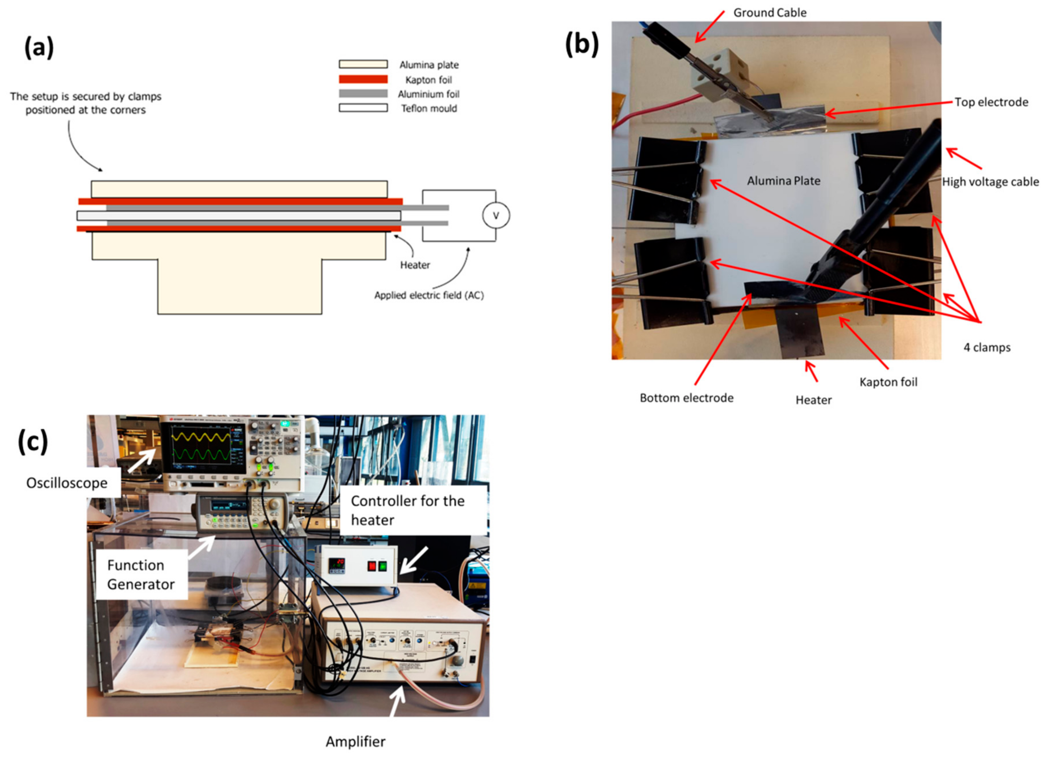
Figure 2.
Differential scanning calorimetry (DSC) curves for melting cyclic butylene terephthalate (CBT) polymer: (a) first heating; and (b) second heating.
Figure 2.
Differential scanning calorimetry (DSC) curves for melting cyclic butylene terephthalate (CBT) polymer: (a) first heating; and (b) second heating.

Figure 3.
(a,b) Lead zirconium titanate-polymerized CBT (PZT–pCBT) composite without application of electric field; (c,d) structured PZT–pCBT composite; and (e) magnified image of structured PZT–pCBT composite.
Figure 3.
(a,b) Lead zirconium titanate-polymerized CBT (PZT–pCBT) composite without application of electric field; (c,d) structured PZT–pCBT composite; and (e) magnified image of structured PZT–pCBT composite.
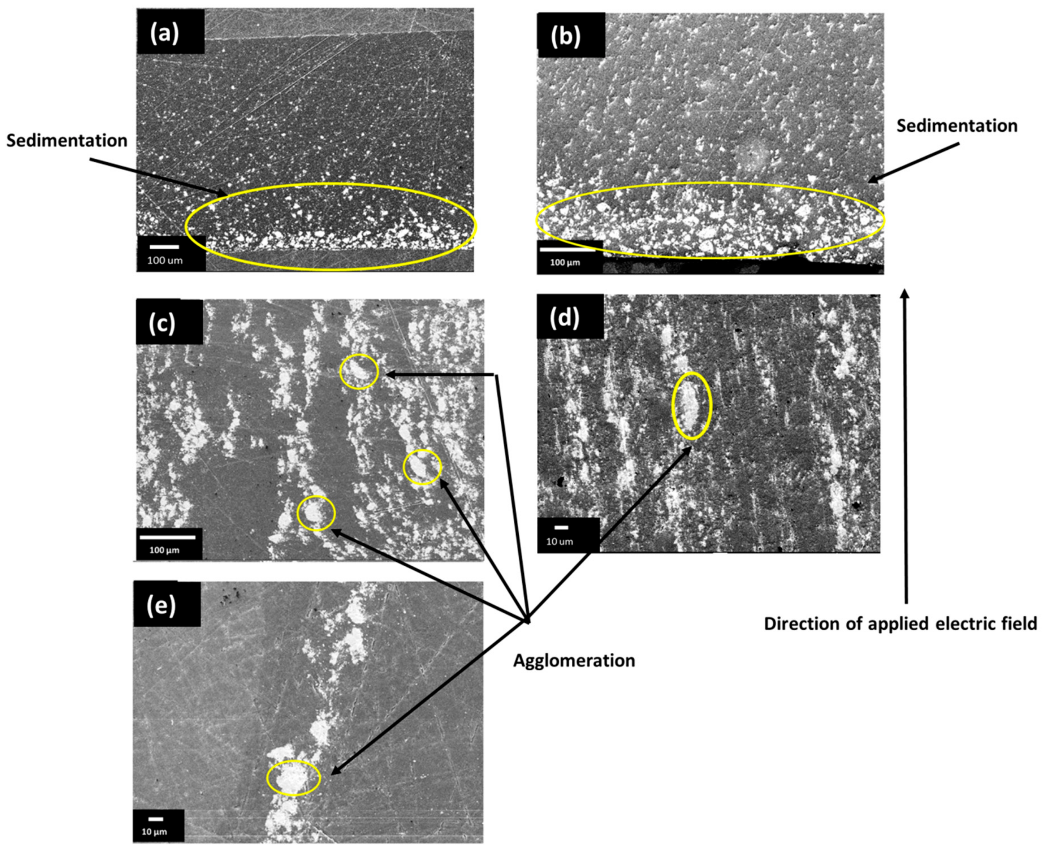
Figure 4.
Piezoelectric and dielectric properties of PZT–pCBT composites; (a) variation of dielectric constant with increasing vol% of PZT; (b) variation of d33 with increasing vol% of PZT; (c) variation of g33 with increasing vol% of PZT compared with epoxy–PZT composite [3].
Figure 4.
Piezoelectric and dielectric properties of PZT–pCBT composites; (a) variation of dielectric constant with increasing vol% of PZT; (b) variation of d33 with increasing vol% of PZT; (c) variation of g33 with increasing vol% of PZT compared with epoxy–PZT composite [3].
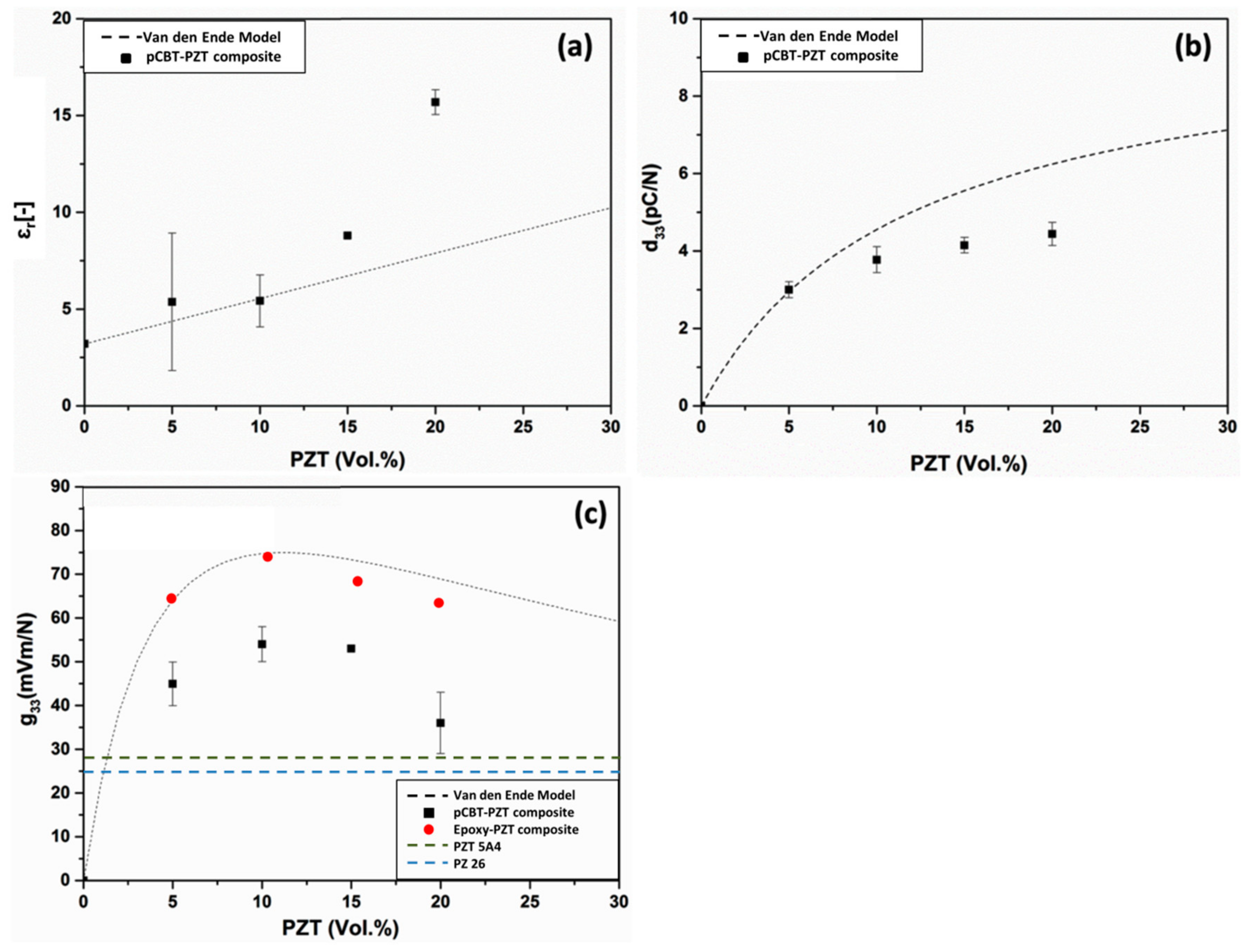
Figure 5.
(a) Time required manufacturing a thermosetting based composite using conventional technique and (b) time required to prepare a thermoplastic based composite using high-temperature dielectrophoresis technique.
Figure 5.
(a) Time required manufacturing a thermosetting based composite using conventional technique and (b) time required to prepare a thermoplastic based composite using high-temperature dielectrophoresis technique.
© 2019 by the authors. Licensee MDPI, Basel, Switzerland. This article is an open access article distributed under the terms and conditions of the Creative Commons Attribution (CC BY) license (http://creativecommons.org/licenses/by/4.0/).
Share and Cite
MDPI and ACS Style
Khaliq, J.; Hoeks, T.; Groen, P. Fabrication of Piezoelectric Composites Using High-Temperature Dielectrophoresis. J. Manuf. Mater. Process. 2019, 3, 77. https://doi.org/10.3390/jmmp3030077
AMA Style
Khaliq J, Hoeks T, Groen P. Fabrication of Piezoelectric Composites Using High-Temperature Dielectrophoresis. Journal of Manufacturing and Materials Processing. 2019; 3(3):77. https://doi.org/10.3390/jmmp3030077
Chicago/Turabian StyleKhaliq, Jibran, Theo Hoeks, and Pim Groen. 2019. "Fabrication of Piezoelectric Composites Using High-Temperature Dielectrophoresis" Journal of Manufacturing and Materials Processing 3, no. 3: 77. https://doi.org/10.3390/jmmp3030077