The Joint Properties of 5754 Aluminium Alloy by Friction Stir Spot Welding

1
Department of Automotive Engineering, Graduate School of Natural and Applied Sciences, Uludag University, 16059 Gorukle-Bursa, Turkey
2
Department of Automotive Engineering, Faculty of Engineering, Uludag University, 16059 Gorukle-Bursa, Turkey
*
Author to whom correspondence should be addressed.
J. Manuf. Mater. Process. 2019, 3(1), 8; https://doi.org/10.3390/jmmp3010008
Submission received: 20 December 2018
/
Revised: 12 January 2019
/
Accepted: 15 January 2019
/
Published: 16 January 2019
Abstract
:In this study, AA5754 sheet samples joined by using a friction stir spot welding method using different rotational speed parameters has been analyzed experimentally. During the experiments, rotational speed of the tool was changed while other process parameters and the tool geometry were kept constant. The effect of tool rotational speed on the hardness values, macrostructure, and tensile properties of joints has been investigated and the results of the experiments show the best tensile shear strength and hardness values are obtained for the tool rotation speed of 1850 rpm. According to the macroscopic investigation, all of the fractured samples failed by nugget pullout and the fractured samples have only a single type fracture pattern.
1. Introduction
Weight reduction without affecting the safety performance is a great challenge in the manufacturing of automotive in order to improve fuel economy and reduce emissions. It has been reported that fuel devouring can be decreased by 5.5% for each 10% decline in vehicle weight and a 0.45 kg decline in the weight of a car would decline carbon dioxide emissions by 9.07 kg over the life of the vehicle. An automobile consists of outer panels and a platform, which is typically made of steel and contains the drive system, engine system, and exhaust system. The weight of the platform is around 70% of the total weight of an automobile [1].
Steel has been applied widely in the automotive industry because of its wide range of desirable properties, ease of processing, availability, and recyclability. However, lightweight materials like aluminum have obvious advantages over steel with comparable properties but nearly three times lower density, a resistance of high corrosion, and a high degree of usage reaching 85–95%. Aluminum alloys are promising candidates for replacing equivalent steel assemblies and the use of them in the manufacturing of automotive is increasing recently [1].
For replacing steel with aluminum in the structure of automobiles, it is necessary to explore joining methods that can be used efficiently. Current panel welding techniques used to join steels involve resistance spot welding and self-piercing rivets. However, these welding techniques cannot be applied easily to aluminum alloy, because of its physical properties, particularly surface oxide film. Friction stir spot welding is a derivative of friction stir joining, which was developed by TWI (Abington, UK) in 1991 as a solid-state method for aluminum alloy joining. This novel joining mechanism is advantageous for producing aluminum joints without contamination, blowholes, porosity, and cracks [1].
This study is focused on aluminum alloy 5754, which is the most common aluminum series utilized by the automotive industry. There are many studies on friction stir spot welding of aluminum alloys.
Er [2] studied the optimum welding limits for the friction stir spot welding of AA5005 sheet samples by comparing the mechanical properties of friction stir spot welding and the resistance spot welding method. He found that the samples which are joined by friction stir spot welding have better mechanical properties compared to the samples that are joined with resistance spot weld.
Kulekci and Er [3], studied the effect of dwell time, tool rotational speed, and tool plunge depth parameters of friction stir spot welding using AA5005 sheet samples. They concluded that the optimum welding parameter ranges for; tool dwell time between 5 s and 10 s, tool rotational speed between 1500 rpm and 2000 rpm, and tool plunge depth between 2.2 mm and 2.6 mm. In addition, it is found that tool plunge depth is the most important parameter that influences welding performance.
Kacar et al. [4] studied friction stir spot welding of AA5754 sheet samples using copper interlayer. It was found that the tensile shear load carrying capacities of AA5754 (on the top)—Cu (on the middle)—AA5754 (on the bottom) material welded by using copper interlayer was greater than the welded AA5754 (on the top)—AA5754 (on the bottom) material with the same welding limits without using the copper interlayer.
Bilici et al. [5] searched friction stir spot welding of AA5754-H22 and AA2024-T3 sheet samples by using the Taguchi method. As a result, two types of fracture type; cross-nugget and nugget fracture occurred after the tensile shear test.
Piccini and Svoboda [6] studied friction stir spot welding of AA5052-H32 and low carbon steel sheet samples and in addition to the mechanical properties they studied the effect of tool geometry and depth limits of the process.
Jeon et al. [7] explored the mechanical properties of AA5052-H32 and AA6061-T6 sheet samples welded by friction stir spot welding process. The value of the highest tensile shear strength was obtained for the AA5052 (on the top)—AA5052 (on the bottom) sample combination. The value of the lowest tensile shear strength was obtained for the AA6061 (on the bottom)—AA6061 (on the top) sample combination.
Due to its potential in light-weigthing applications of automotive and other relevant industries, friction stir spot welding can be spread in many industries.
For this purpose, three different experimental configurations were created with AA5754 sheet samples (thickness of 1 mm). These samples were welded by friction stir spot welding with three different unstudied tool rotational speeds and most common tool geometry. Then, tensile shear strength test, microhardness test, and macrostructure analysis were performed on these samples.
2. Experimental Procedure
2.1. Material and Its Properties
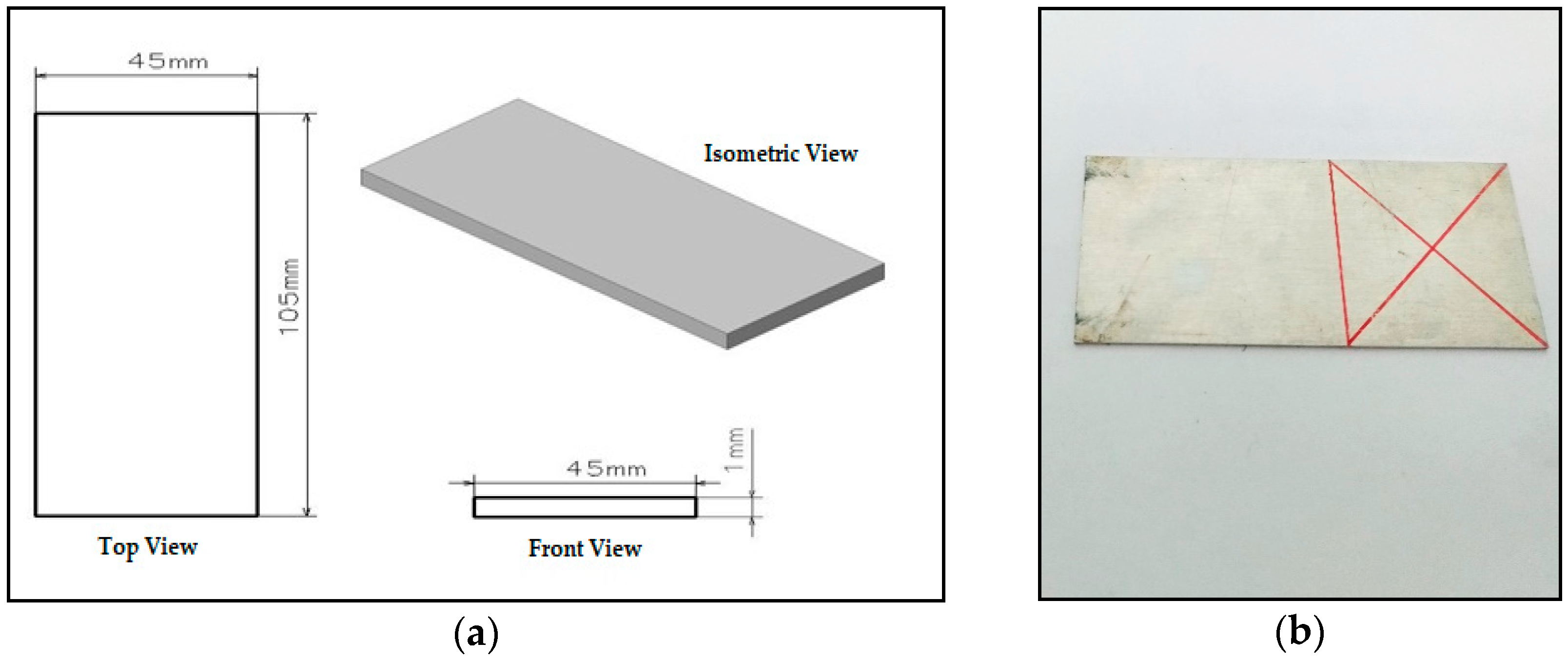
In this study, the aluminum alloy 5754 sheets of 1 mm thickness were produced in accordance with the American Society for Testing and Materials (ASTM) B209-10 standard. The chemical composition of the aluminum alloy 5754 is given in Table 1 and the mechanical properties are given in Table 2, according to ASTM B209-10, BS EN 485-2:2016, respectively. The test samples were prepared in 45 mm × 105 mm × 1 mm dimensions according to BS EN ISO 14273:2016 (Figure 1a,b).
2.2. Friction Stir Spot Welding Application
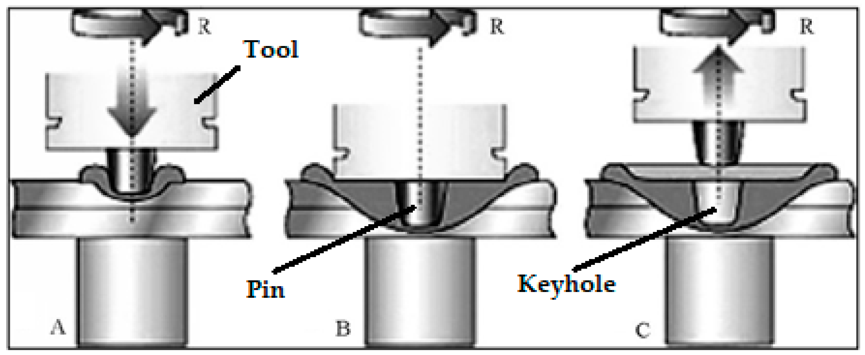
Friction stir spot welding involves simply plunging the rotating tool into the workpiece, holding it there for a certain dwell time and then retracting it (Figure 2). The process is usually used for lap joints where the materials to be joined are stacked on top of one another with a backing plate or anvil underneath to support the downforce. The rotating tool penetrates the top surface, causing heat by friction and softening the material adjacent to the tool. This material flows plastically under the compressive and rotational forces, thus when the tool is removed, the materials have joined with a solid-phase bond in the weld region. Successful welding depends on the tool plunge depth, the tool plunge rate, the tool rotational speed, the tool dwell time, and the tool geometry [8].
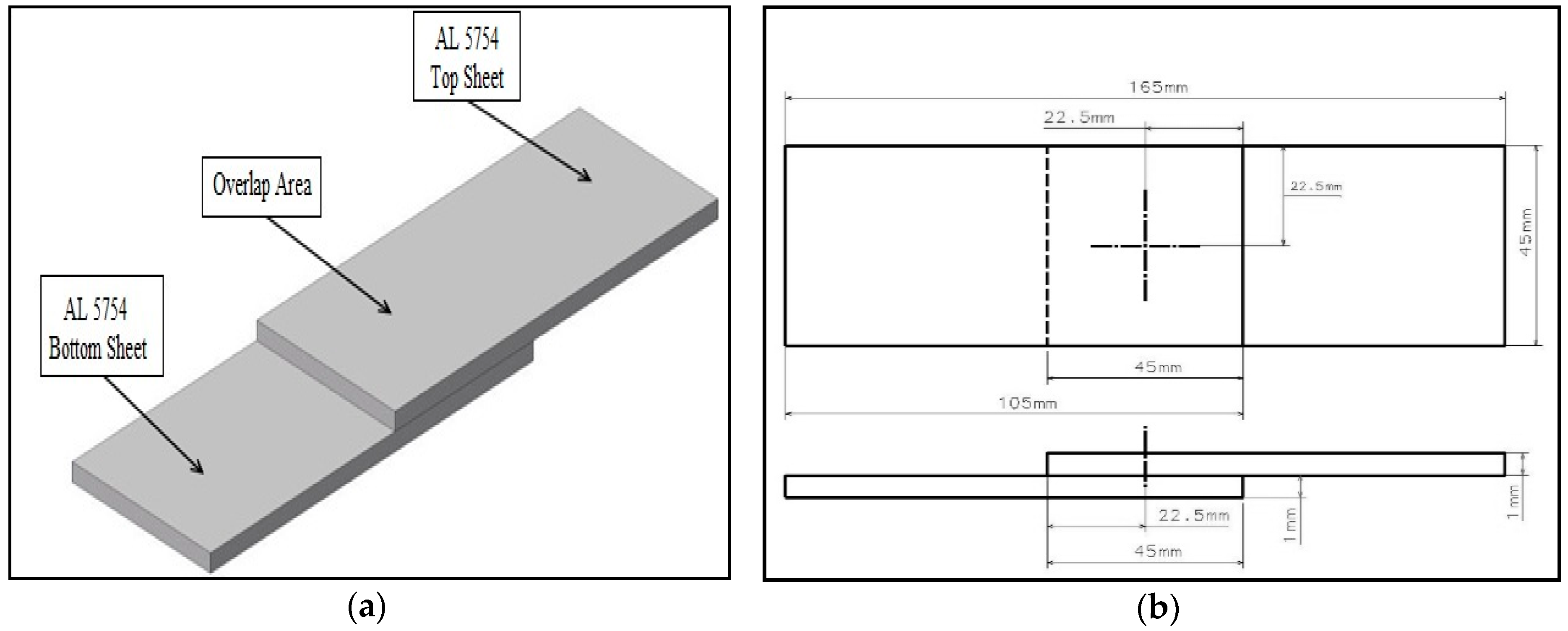
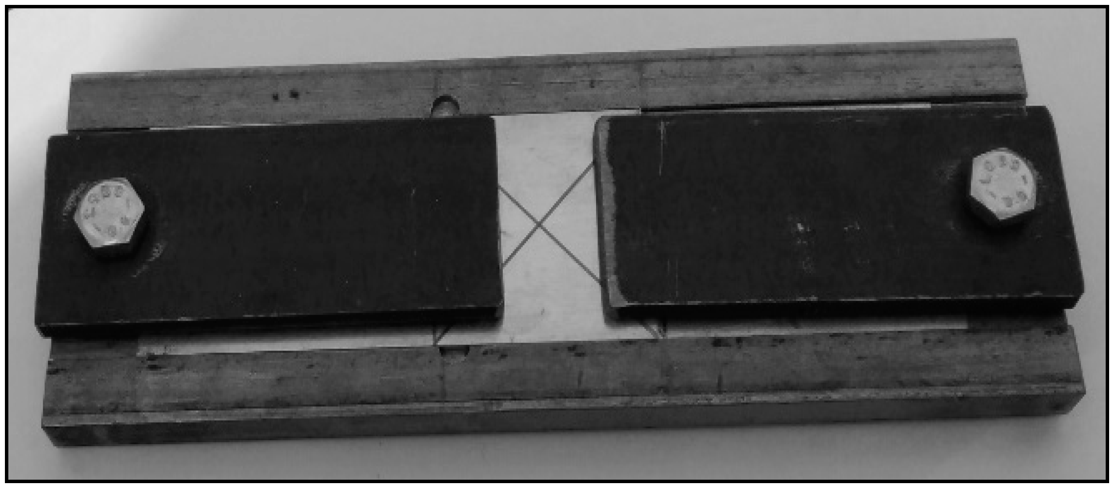
The samples prepared for the experiment were positioned on top of each other (overlap area 45 mm × 45 mm) as shown in Figure 3a,b. The test samples were placed in the welding fixture (Figure 4) in order to fix them during operation and the friction stir spot welding process was applied to the center of the overlap area as shown in Figure 3b. During the experiments, a universal milling machine was used for the friction stir spot welding process.
2.3. Friction Stir Spot Welding Tool
The X153CrMoV12 (1.2379) tool steel produced according to ISO 4957:2018 standard, was used for the friction stir spot welding process. The chemical composition of tool steel is given in Table 3.
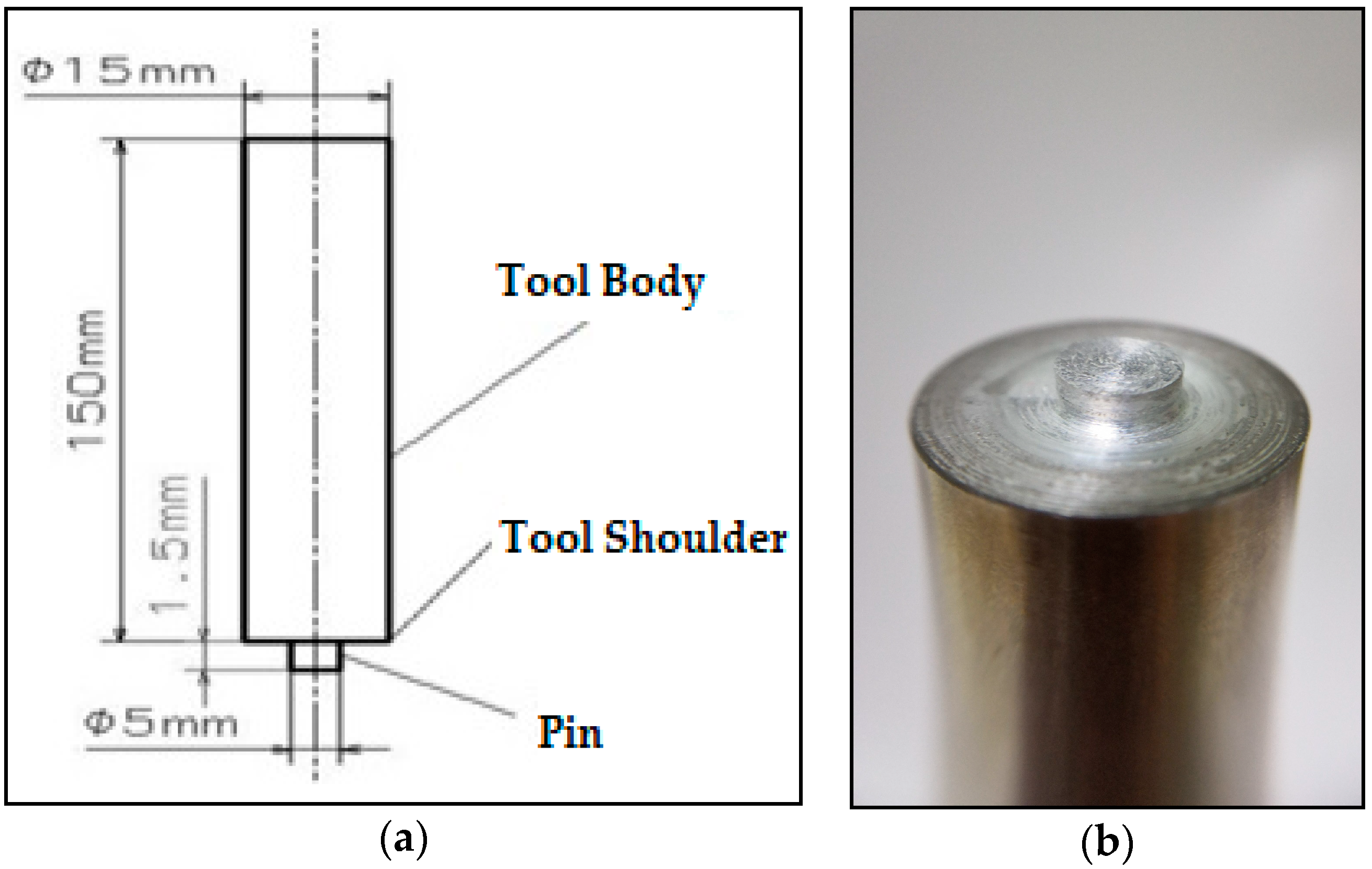
The geometry of the tool is circular pin and this type of geometry has been used by many researchers in the literature for AA5754 material [2,3,9,10]. Dimensions and image of the circular pin are given in Figure 5a,b. In addition, the pin is without a thread. Heat treatment was applied to the tool steel. The hardness of the tool steel after the heat treatment reached 52-54 Hardness of Rockwell (HRC).
2.4. Friction Stir Spot Welding Experiment Limits
Experiments of the friction stir spot welding were carried out for three different tool rotational speeds of 1350, 1850, and 2530, respectively. According to the literature data, these tool rotational speeds were not utilized for the friction stir spot welding process of the AA5754 material. In addition to the variable tool rotational speed the other process parameters; plunge depth, shoulder penetration, tilt angle, and dwell time were kept constant. Details of the constant parameters are given in Table 4.
The constant and variable parameters which have been used during the experiments are given in Table 4 and the experimental configuration details are given in Table 5. For each experimental configuration, five samples were produced, and four of five samples were utilized for tensile shear strength test. The other sample was used for the microhardness measurement.
2.5. Microhardness Testing
Microhardness testing was performed on the weld sections in order to establish local yield stresses. In order to prepare the samples for the microhardness test, samples were cut from the middle of the weld center (weld cross section). Samples were mounted and polished using standard metallographic techniques with sand papers, while paying particular attention to keep the top and bottom surfaces in parallel. The microhardness test measurements were carried out with Metkon MH-3 Vickers Microhardness Test Machine. Tests were conducted under the parameter which are at a load of 100 gr, duration of 10 s, and a spacing of 1 mm. Microhardness measurements of the joint material were performed along the cross-section centerline of the top sheet left side weld area as shown in Figure 6.
2.6. Tensile Shear Strength Test
The tensile shear strength test was performed on four of the five samples for each experimental configuration to determine the tensile shear load. The universal testing machine load capacity of 250 kN was utilized to perform the experiments and tests were carried out using a crosshead travel velocity of 5 mm/min.
2.7. Macrostructure Analysis
The macrostructure of fracture surfaces was examined visually. The macroscopic analysis was performed based on qualitative observation visual examination, and the macrostructure of the welding fracture surfaces was investigated. The examination was carried out for all the samples which were used in the tensile test.
3. Experimental Results
3.1. Tensile Properties of Joints
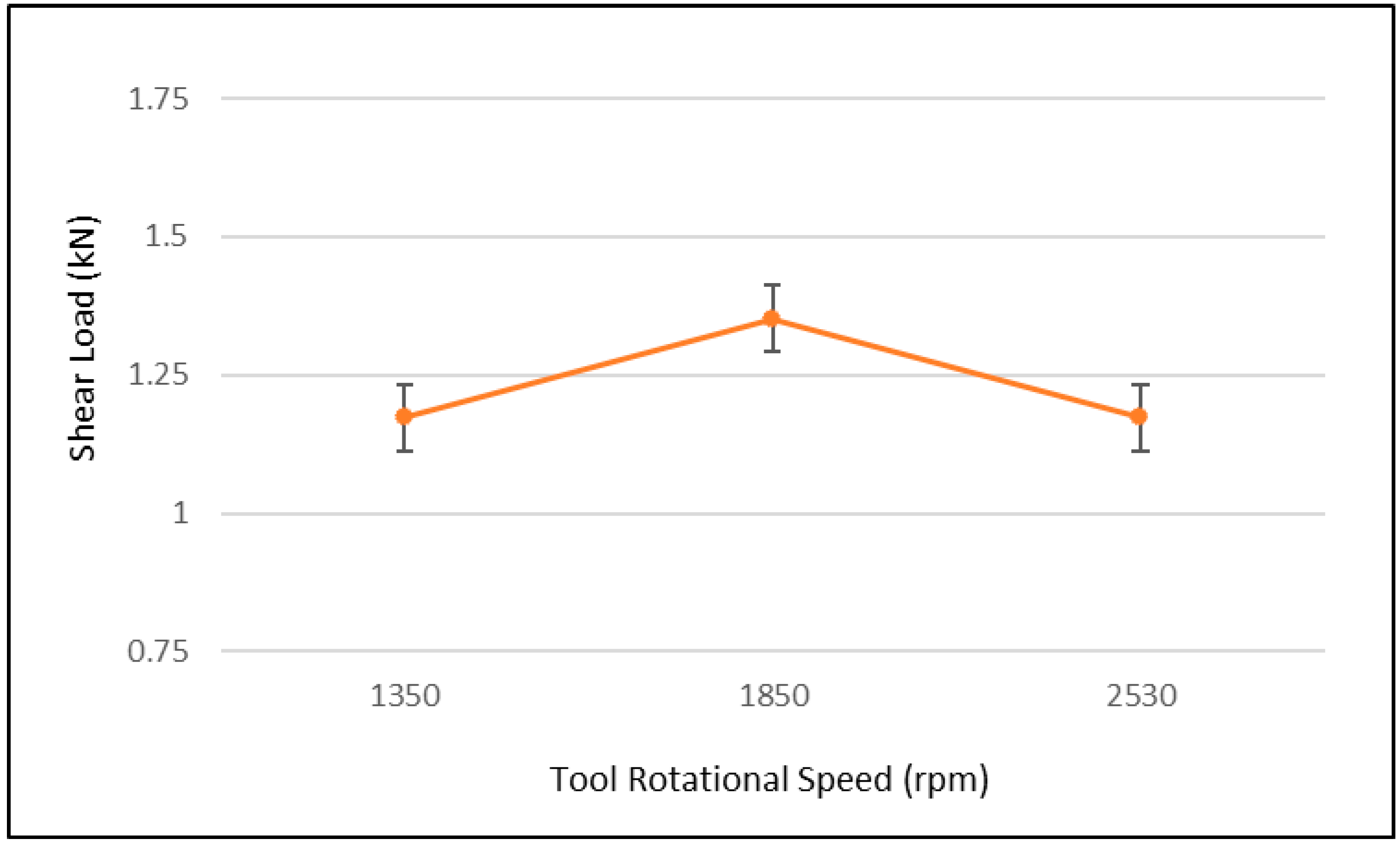
During the experiments, the tensile shear load of the joints was obtained, and the average values of the tensile test loads were calculated for all experimental configurations. The graphical presentation of the average tensile shear load values is shown in Figure 7.
The average tensile shear load values of experimental configurations are 1.1725, 1.35 and 1.1733 kN for 1350, 1850, and 2530 rpm, respectively.
The difference between the tensile shear load value obtained at 1350 and 2530 rpm, was found to be quite low. The maximum tensile shear load was measured as 1.35 kN at 1850 rpm and the minimum tensile shear load was measured as 1.17 kN at 1350 rpm. The tensile shear load was augmented by 15.38% when the tool rotation speed was increased from 1350 rpm to 1850 rpm. On the other hand, the tensile shear load was decreased by 13.33%, while the tool rotation speed was increased from 1850 rpm to 2530 rpm. The obtained results show that the tool rotational speed was an important parameter in lap shear strength.
The tensile shear load was increased for all the experiments, as the tool rotation speed was increased from 1350 to 1850 rpm. According to Güler [11] explained that an increase in the tensile shear load may be explained with the microstructural changes due to the heat generation at a stirring location. On the other hand, the tensile shear load was decreased when the tool rotational speed was increased from 1850 to 2530 rpm. This situation can be explained by more frictional energy generation due to the increment of tool rotational speed and the fluidity of the plasticized material in the stirring zone being increased, as supported by reference [12].
3.2. Hardness Values of Joints
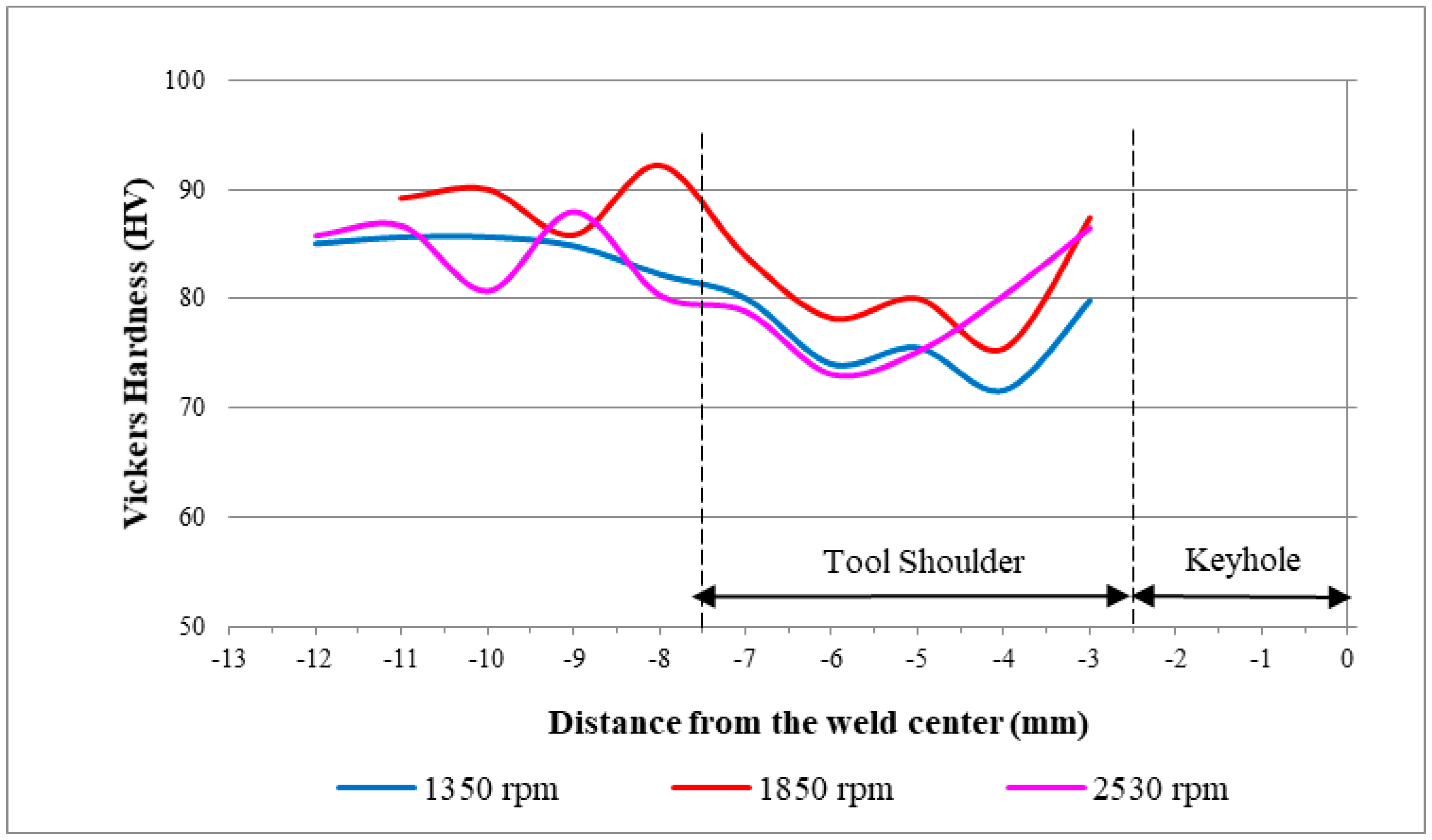
The Vickers hardness values were obtained for the three different rotational speeds of the joints welded by the welding tool are shown in Figure 8.
The hardness values for the friction stir spot welding via the welding tool are shown in Figure 8. Maximum and minimum hardness values were obtained as 92.2 and 71.6 HV at the tool rotational speeds of 1850 and 1350 rpm, respectively. Minimum and maximum hardness values of all experimental configurations are presented in Table 6.
In the keyhole area of the joints, greater hardness values were obtained. Regarding this situation, Güler [13] explained that the plastic deformation in the welding process causes strain hardening, which is the main reason of the hardness increase. During the welding process, fine grains that consisted with the dynamic recrystallizations are the reason for this situation.
According to Figure 8, from the weld center to the base metal hardness profile, it is firstly reduced and then a gradual increment occurs, and the trend of the hardness profile is in good agreement with the existing literature data [6,14,15,16].
As a result of the tensile shear test, it is found that test groups with maximum strength values have maximum hardness values. The plastic deformation generates an increment in the hardness and strength and Güler [13] reported that both of them are raised together, contingent upon dynamic recrystallization.
3.3. Macrostructure of Joints
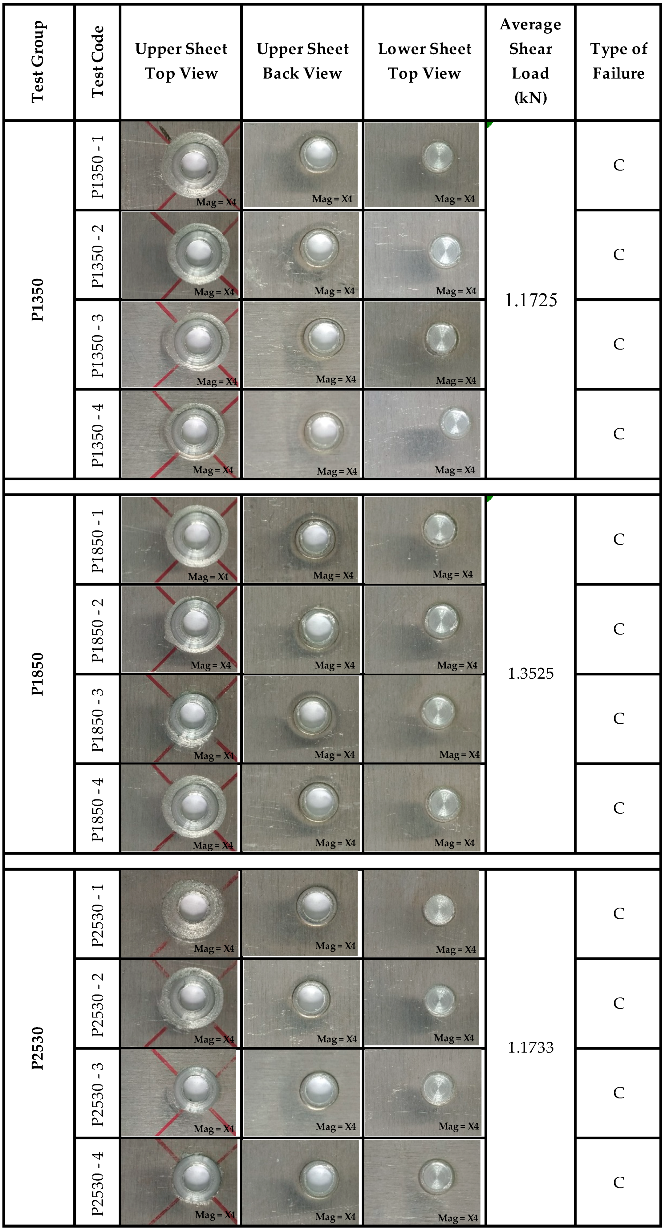
In the literature, generally, three failure modes are observed after the shear tests for friction stir spot welding. These are, mode 1—shear failure: The failure occurs along the joint line of betwixt the sheets (sheet thickness> 2 mm); mode 2—mixed cleavage failure: The diminish stamina failure begins by cleavage, pursuing the oxide debris describing the surfaces betwixt the sheets; and mode 3—nugget pullout: The joint’s interface doesn’t fail, and the tears circumference the shoulder edge on the upper sheet contact surface, and are separated and connected to the welding nugget on the lower sheet. This failure mode is also stimulated by thinning of the top sheet on the side of the tool shoulder, depending on the tool shoulder plunge process [13].
In this study, macrostructures of fractured surfaces of the samples were investigated for all experimental configurations.
All the test samples were investigated based on qualitative visual inspection. The failure modes of all fractured welding joints are shown in Figure 9. In addition, upper sheet top view, upper sheet back view, lower sheet top view, and the average shear load values are given in Figure 9.
In all fractures, failure mode 3 was observed as a single type of fracture pattern.
A single fracture pattern; failure mode 3 was observed for all experimental configurations and the increase in the tool speed from 1350 to 2530 rpm did not affect the failure pattern.
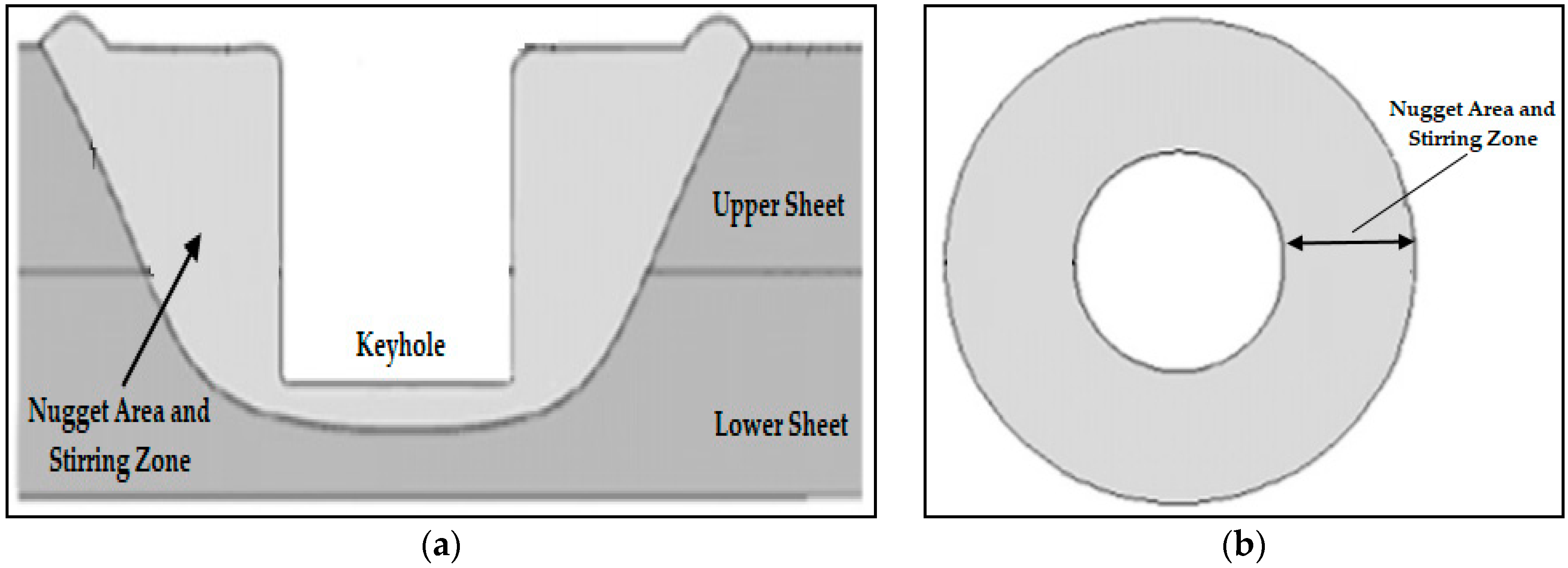
A nugget area around the tool pin length was formed by plasticized material blending into each other during the friction stir spot welding. The nugget area is given in Figure 10a,b. The nugget area contains materials of lower and upper sheets due to the physical phenomenon of the process. During the tensile shear test, the fracture occurs at the outer contour of the welding area and proceeds around the welded section, and it keeps proceeding until the lower and upper sheets are separated from each other.
It was observed that the fracture propagation occurs parallel according to the upper sheet surface. Therefore, this failure type is named as a nugget pullout failure and our findings are supported by the existing literature data.
4. Conclusions
In this work, the effects of the tool rotational speed and the tool geometry parameters on the mechanical properties of the friction stir spot welding of the AA5754 aluminum alloy were investigated in terms of hardness values and fracture morphologies. The tool geometry is a circular pin and rotational tool speed is taken as 1350, 1850, and 2530 rpm for experimental configurations.
The following conclusions were made:
- Increasing rotational tool speed from 1350 to 1850 rpm caused an increase in the tensile shear load and harness values but they are diminished when the tool speed is increased to 2350 rpm. It is concluded that the plastic deformation in the welding process causes strain hardening, which is the main reason for the hardness increase. During the welding process, fine grains that consisted with dynamic recrystallizations are the reason for this situation.
- It is found that experimental configurations with the maximum strength values have the maximum hardness values. The best value of tensile shear strength and hardness are taken place at the tool rotation speed of 1850 rpm.
- A single fracture pattern; failure mode 3 was observed for all experimental configurations and the increase in the tool speed from 1350 to 2530 rpm did not affect the failure pattern.
Author Contributions
H.G.Ö. designed the experiment, O.D. and H.G.Ö. performed the tensile tests. O.D. performed the hardness tests and the macrostructure of the joints. O.D. wrote and H.G.Ö. supervised the manuscript.
Funding
This research was funded by Bursa Uludag University.
Acknowledgments
This study was supported by Uludag University, Department of Scientific Research Projects (Project No: KUAP(M)-2013/53). The authors would like to thank the department for their valuable support.
Conflicts of Interest
The authors declare no conflict of interest.
References
- Wei, Y. Friction Stir Spot Welding of Aluminum Alloys. Master’s Dissertation, Missouri University of Science and Technology, Rolla, MO, USA, 2008. [Google Scholar]
- Er, O. Elektrik Direnç ve Sürtünme Karıştırma Nokta Kaynaklı Alüminyum Alaşımı Bağlantıların Mekanik Özelliklerinin İncelenmesi. Master’s Dissertation, Mersin University—Institute of Science and Technology, Mersin, Turkey, 2010. [Google Scholar]
- Külekçi, M.K.; Er, O. Sürtünme Kariştirma Nokta Kaynakli EN AW—5005 (Al Mg1) Alüminyum Alaşımı İçin Optimum Kaynak Parametre Seviyelerinin Belirlenmesi. J. Fac. Eng. Arch. Gazi Univ. 2012, 27, 537–545. [Google Scholar]
- Kaçar, R.; Emre, H.E.; Demir, H.; Gündüz, S. Al-Cu-Al Malzeme Çiftinin Sürtünme Kariştirma Nokta Kaynak Kabiliyeti. J. Fac. Eng. Arch. Gazi Univ. 2011, 26, 349–357. [Google Scholar]
- Bilici, M.K.; Bakır, B.; Bozkurt, Y.; Çalış, İ. Sürtünme karıştırma nokta kaynak tekniği ile birleştirilen farklı alüminyum levhaların taguchi analizi. Pamukkale Univ. J. Eng. Sci. 2016, 22, 17–23. [Google Scholar] [CrossRef]
- Piccini, J.M.; Svoboda, H.G. Tool geometry optimization in friction stir spot welding of Al-steel joints. J. Manuf. Process. 2017, 26, 142–154. [Google Scholar] [CrossRef]
- Jeon, C.S.; Hong, S.T.; Kwon, Y.J.; Cho, H.H.; Han, H.N. Material properties of friction stir spot welded joints of dissimilar aluminum alloys. Trans. Nonferrous Met. Soc. China 2012, 22, 605–613. [Google Scholar] [CrossRef]
- Panteli, A. Friction Joining of Aluminium-to-Magnesium for Lightweight Automotive Applications. Ph.D. Dissertation, University of Manchester—Faculty of Engineering and Physical Sciences, Manchester, UK, 2012. [Google Scholar]
- Kahraman, B. Otomotiv Endüstrisinde Kullanılan 5754 Alüminyum Alaşımı Sacların Direnç Nokta Kaynağı (RSW) ve Sürtünme Karıştırma Nokta Kaynağı (FSSW) Yöntemleri ile Birleştirilmesi. Master’s Dissertation, Kocaeli University—Institute of Science and Technology, Kocaeli, Turkey, 2009. [Google Scholar]
- Bozkurt, Y.; Bilici, M.K. Application of Taguchi approach to optimize of FSSW parameters on joint properties of dissimilar AA2024-T3 and AA5754-H22 aluminum alloys. Mater. Des. 2013, 51, 513–521. [Google Scholar] [CrossRef]
- Güler, H. Influence of the Tool Geometry and Process Parameters on the Static Strength and Hardness of Friction-Stir Spot-Welded Aluminium-Alloy Sheets. Mater. Technol. 2015, 49, 457–460. [Google Scholar] [CrossRef]
- Ojo, O.O. 2219 Alüminyum Alaşımının Sürtünme Karıştırma Nokta Kaynaklı Bağlantılarının Özellikleri ve Deneysel Tasarımla Optimizasyonu. Ph.D. Dissertation, Kocaeli University—Institute of Science and Technology, Kocaeli, Turkey, 2016. [Google Scholar]
- Güler, H. The Mechanical Behavior of Friction-Stir Spot Welded Aluminum Alloys. JOM 2014, 66, 2156–2160. [Google Scholar] [CrossRef]
- Piccini, J.M.; Svoboda, H.G. Effect of the Tool Penetration Depth in Friction Stir Spot Welding (FSSW) of Dissimilar Aluminum Alloys. Procedia Mater. Sci. 2015, 8, 868–877. [Google Scholar] [CrossRef] [Green Version]
- Zhang, Z.; Yang, X.; Zhang, J.; Zhou, G.; Xu, X.; Zou, B. Effect of welding parameters on microstructure and mechanical properties of friction stir spot welded 5052 aluminum alloy. Mater. Des. 2011, 32, 4461–4470. [Google Scholar] [CrossRef]
- Wang, D.-A.; Lee, S.-C. Microstructures and failure mechanisms of friction stir spot welds of aluminum 6061-T6 sheets. J. Mater. Process. Technol. 2007, 186, 291–297. [Google Scholar] [CrossRef]
Figure 1.
Dimensions (a) and image (b) of test sample.

Figure 2.
Schematic drawing of the friction stir spot welding application (A: Plunging, B: Stirring, C: Retracting) [8].
Figure 2.
Schematic drawing of the friction stir spot welding application (A: Plunging, B: Stirring, C: Retracting) [8].

Figure 3.
(a) The isometric view for welding position of the samples. (b) The dimension of the top view and the side view for the welding position of the samples.
Figure 3.
(a) The isometric view for welding position of the samples. (b) The dimension of the top view and the side view for the welding position of the samples.

Figure 4.
The welding fixture.

Figure 5.
Dimensions (a) and image (b) of the tool used for friction stir spot welding experiments.

Figure 6.
The microhardness measurement position of the sample.

Figure 7.
Shear load for the friction stir spot welding via welding tool at different tool rotational speed.
Figure 7.
Shear load for the friction stir spot welding via welding tool at different tool rotational speed.

Figure 8.
The Vickers hardness values of friction stir spot welding via the welding tool at three different rotational speeds.
Figure 8.
The Vickers hardness values of friction stir spot welding via the welding tool at three different rotational speeds.

Figure 9.
Failure modes of broken test samples. (C: Mode 3; nugget pullout failure).

Figure 10.
(a) The cross-section view of the friction stir spot welding and (b) top view of the nugget area and the stirring zone [12].
Figure 10.
(a) The cross-section view of the friction stir spot welding and (b) top view of the nugget area and the stirring zone [12].


Table 1.
Chemical composition of the AA5754.
| Cu | Si | Fe | Cr | Mg | Ti | Mn | Zn | Other Elements | Al | |
|---|---|---|---|---|---|---|---|---|---|---|
| Chemical Composition (%) | 0.1 | 0.4 | 0.4 | 0.3 | 2.6–3.6 | 0.15 | 0.5 | 0.2 | 0.15 | 94.2–95.2 |
Table 2.
Mechanical properties of the AA5754.
| Yield Strength (MPa) | Tensile Strength (MPa) | Elongation (%) | Hardness (HBV) |
|---|---|---|---|
| 80 | 190–240 | 14 | 52 |
Table 3.
Chemical composition of tool steel.
| Mn | Si | V | Cr | C | Mo | |
|---|---|---|---|---|---|---|
| Chemical Composition (%) | 0.2–0.6 | 0.1–0.6 | 0.7–1.0 | 11–13 | 1.45–1.6 | 0.7–1 |
Table 4.
Process parameters.
| Dimension | Value |
|---|---|
| Tool rotational speed | 1350, 1850, 2530 rpm |
| Plunge depth | 1.6 mm |
| Shoulder penetration | 0.1 mm |
| Tilt angle | 0° |
| Dwell time | 6 s |
Table 5.
Experimental configuration of the friction stir spot welding process.
| Test Case | Test Code | Tool Rotational Speed (rpm) |
|---|---|---|
| 1 | P1350 | 1350 |
| 2 | P1850 | 1850 |
| 3 | P2530 | 2530 |
Table 6.
Maximum and minimum hardness values for different experimental configurations.
| Case | Tool Rotational Speed | Min. Hardness (HV) | Max. Hardness (HV) |
|---|---|---|---|
| 1 | 1350 | 71.6 | 85.6 |
| 2 | 1850 | 75.4 | 92.2 |
| 3 | 2530 | 73.0 | 86.7 |
© 2019 by the authors. Licensee MDPI, Basel, Switzerland. This article is an open access article distributed under the terms and conditions of the Creative Commons Attribution (CC BY) license (http://creativecommons.org/licenses/by/4.0/).
Share and Cite
MDPI and ACS Style
Dedeoğlu, O.; Güler Özgül, H. The Joint Properties of 5754 Aluminium Alloy by Friction Stir Spot Welding. J. Manuf. Mater. Process. 2019, 3, 8. https://doi.org/10.3390/jmmp3010008
AMA Style
Dedeoğlu O, Güler Özgül H. The Joint Properties of 5754 Aluminium Alloy by Friction Stir Spot Welding. Journal of Manufacturing and Materials Processing. 2019; 3(1):8. https://doi.org/10.3390/jmmp3010008
Chicago/Turabian StyleDedeoğlu, Orhan, and Hande Güler Özgül. 2019. "The Joint Properties of 5754 Aluminium Alloy by Friction Stir Spot Welding" Journal of Manufacturing and Materials Processing 3, no. 1: 8. https://doi.org/10.3390/jmmp3010008