Development of Steps in an Automated Process Chain for Piezoceramic-Metal Compound Production


1
Fraunhofer-Institut für Werkzeugmaschinen und Umformtechnik, Reichenhainer Straße 88, 09126 Chemnitz, Germany
2
Professur für Adaptronik und Funktionsleichtbau, Technische Universität Chemnitz, Straße der Nationen 62, 09111 Chemnitz, Germany
*
Author to whom correspondence should be addressed.
J. Manuf. Mater. Process. 2019, 3(1), 3; https://doi.org/10.3390/jmmp3010003
Submission received: 10 December 2018
/
Accepted: 25 December 2018
/
Published: 7 January 2019
(This article belongs to the Special Issue Analysis and Modeling of Sheet Metal Forming Processes)
Abstract
:Featured Application
Piezoceramic-metal compounds have the opportunity to break fresh ground in condition monitoring of automotive products and white goods while providing additional actuator capabilities using the piezoelectric effect. Structural health monitoring, detection of crash load cases and energy harvesting are possible areas of application as well as vibration/noise reduction, noise generation (electric vehicles) and shape control.
Abstract
The potential of adaptronic applications has been proven in many conceptual studies. A broad use in high-efficiency branches is often hindered by the absence of an appropriate assembly method. Especially for piezoceramic foil transducers, the application on structural parts can be simplified using a semi-finished part that includes the transducer. The part is then shaped in a final forming operation. The purpose of the present study is the investigation of process limits in automated process chains for producing semi-finished parts. An adhesive is used in the process, which is only locally cured. This bi-conditioned state is achieved using cooling and heating elements. The process limits are mainly affected by the choice of temperature and curing time between adhesive application and forming operation. Several tests with a rotational rheometer were carried out to investigate the curing behavior. An appropriate process window was identified varying processing time and temperature. The results were then used to build a model of the curing behavior. A mathematical approach had to be used to find the best configuration because no sharp border exists between the two adhesive conditions of liquid and solid state. The process parameters were proven with runs inside and outside of the process limits.
1. Introduction
Adaptronic applications have gained a lot of attention in recent years. In many cases, the basis is an integration of a smart material into parts. Smart materials change their internal structure or property when applying an external stimulus. They convert one energy form into another. Hence, smart materials can be used to react to changed external conditions and to respond with an appropriate answer in a useful manner [1]. Examples are Shape Memory Alloys (SMA), Dielectric Elastomers (DE), Magnetorheological Fluids (MRF), magnetostrictive alloys, photovoltaics and piezoceramics. The latter can be used very efficiently in both conversion directions: an applied mechanical pressure causes a charge on the surface of the ceramic. Inversely, a mechanical strain occurs in the ceramic if an electric field is applied. This predestines piezoceramics for usage in smart structures in order to provide an adaptronic system. According to the working direction, the transducers operate as actuators when an electric field is applied, or as sensors when a measurable electric signal is tapped due to piezoceramic deformation.
Notwithstanding the above, the wide distribution of adaptronic applications is often hindered by the lack of appropriate production methods. Especially in high-efficiency process chains, the application strategy for integrating smart materials must meet the demands for fast and robust assembly. Thin foil transducers are utilized for structural parts such as car bodies. Typically, they are applied via bonding after shaping of the parts [2,3,4]. In this additional production step under laboratory conditions, additional elements are used to fix the transducer onto curved sheet metals while the adhesive fully cures. Plurally curved part design is hardly ever feasible using the standardized rectangular transducer geometries because of the draping properties of the stiff foils.
Early research with hybrid sandwich-compounds of this kind was carried out for aramid-reinforced aluminum laminates (Arall), carbon-reinforced aluminum laminates (Carall) and glass-reinforced aluminum laminates (Glare). The compounds consist of alternating layers of metal and fiber reinforcement. An overview is given in [5,6]. The highest effort was spent on the investigation of metal-polymer-metal compounds, which exhibit excellent damping properties [7]. The formability of such compounds was investigated in several studies [8,9]. Additional reinforcements were added with textile inserts [10,11]. The formerly commercially available metal-polymer-metal compounds Sollight, Hylite, Hybrix and Alulight were compared in [12]. Compounds with a stiffer core material show better incremental formability. Only [13,14] theoretically consider a possibility to integrate flat sensors into the compound. Integration of actuator/sensor capability utilizing piezoceramic foil transducers was not in the scope of the investigation.
The present study deals with production methods for piezoceramic compounds which can be used as actuators and sensors. Special focus in the investigated process chain lies in its suitability for automation. The utilized approach transfers the application step into the forming operation by using an additional cover sheet-metal that shields the transducer from production loads and from loads during the subsequent work life. The piezoceramic transducer is embedded in a liquid adhesive that acts as a lubricant. At the same time, liquid adhesive and transducer are encapsulated by a cured outer adhesive to ensure the mechanical stability of the stack. The semi-finished plane compound is then shaped in a conventional forming process. Previous studies showed the practicability of this method [15]. Nevertheless, the application method has to be adopted for the process chain. Two adhesive conditions, cured and uncured at the same time, can be provided by thermal treatment that increases the curing reaction velocity in case of heating and decelerates the curing process in case of cooling. The temperatures have to match the process sequence. Hence, the curing behavior of adhesive Sika Fast 5215 NT (manufacturer Sika Deutschland GmbH, Stuttgart, Germany) was investigated using a rotational rheometer. With the results, a process window was found that secures the uncured state of the inner adhesive while providing the structural integrity in the outer zones. In a final study, the optimum process was compared with production using parameters outside of the process window. The residual performance of the formed piezoceramic compounds in the suboptimal process is decreased due to prematurely cured inner adhesive. A method is defined that allows for locating the proper process window and helps process planning and monitoring.
2. Materials and Methods
2.1. Adhesive Sika Fast 5215 NT
2.1.1. Curing Kinetics and Mechanical Properties
Sika Fast 5215 NT is a 2-component adhesive. The curing kinetics is driven by a chemical reaction of acrylate-based resin and hardener. The optimum reaction starts when the two components are mixed up with a fixed volume ratio of 1:10. The datasheet gives a handling time of 15 [16]. Elevated temperatures accelerate the curing process. A low Young’s modulus of approx. 250 in conjunction with high tensile rupture strain of 200% and ultimate shear strength of 10 yield an excellent suitability for gap bridging between joint members undergoing high deformations and relative displacements.
2.1.2. Identification of Rheological Properties
A rheometer (manufacturer Thermo Fisher Scientific, Waltham, MA, USA, type Haake Mars 60) is available at Fraunhofer Institute for Machine Tools and Forming Technology (IWU), using disposable plate-plate geometries to induce shear gradients in a circular material specimen. Although constant rotation measurement is available, an oscillation measurement mode (upper rotating plate oscillates around zero position with small positive and negative rotation angle amplitudes) is used in the present study due to complete curing of adhesive. The disposable measurement geometries (aluminum) have a diameter of 20 . All measurements in the present study were carried out with an oscillation amplitude of and a frequency of 1 . The amplitude value was identified in preliminary tests. The value has to be low enough to avoid rupture in the solid adhesive state and high enough to cause a measurable signal in the liquid state. A standard value was used for the frequency. Furthermore, the specimen is loaded with several isothermal temperatures between 15 °C and 55 by a Peltier element in the bearing of the lower rigid plate under the specimen. An insulating passive dome is fixed over the upper plate and the specimen. The measured rheological properties such as storage and loss modulus, phase shift and necessary torque are internally calculated and outputted after measurement completion. The measurement of time starts when resin and hardener are mixed to include the starting point for the curing reaction.
2.1.3. Dielectric Analysis (DEA)
The curing behavior of the adhesive was investigated using dielectric analysis (DEA), which evaluates the electrical properties applying an alternating electric field. Dielectric sensors are placed in the liquid adhesive. The commercially available sensors (manufacturer Netzsch Gerätebau GmbH, Selb, Germany, type IDEX 115) contain interdigitated electrodes that provide an electrical field in the contacting specimen. Together with an impedance-meter (LCR-meter), they measure capacitance and conductance of the specimen. The adhesive material shows significant change in electrical properties while curing takes place. In the uncured state, the dipole molecules and ions can move freely. The dipoles rotate and are oriented when applying an external electric field. The ions flow according to the field orientation. With increasing crosslink density, i.e., increasing molecular weight during curing, the mobility decreases and conductance as well as the loss factor (measurement of amount of dissipated energy) decrease, while the capacitance increases. Preliminary tests with the rotational rheometer Haake Mars 60 were conducted to secure the applicability of DEA with the present adhesive system Sika Fast 5215 NT. Viscosity and loss angle were measured simultaneously with the rheometer and LCR-meter (manufacturer PeakTech Prüf- und Messtechnik GmbH, Ahrensburg, Germany, type 2155), respectively. The LCR-meter settings for the measurement were chosen to a frequency of 1 and a voltage of 1 . The flat dielectric sensors were located in the adhesive gap between a lower rigid and an upper rotating measuring plate. The tests showed very comparable principle curve shapes, especially according to the reversal point locations.
2.2. Aluminum Sheets
For the production of piezoceramic-metal compounds aluminum sheets are used as basic and cover sheets. The aluminum material AA5083 is employed with thicknesses of 1.0 mm and 1.5 and dimensions of . In a former study [17], the strain hardening characteristic was investigated in uniaxial tension tests via true stress/true strain curves. An approximation based on Voce-extrapolation was made. With A, , being the coefficients of the approximation, the true stress and the true strain. The coefficients were identified as (initial elastic stress limit), , , and .
2.3. Macro Fiber Composites (MFC)
MFC are commercially available foil transducers, which are widely used in conceptual adaptronic applications. They contain brittle rectangular piezoceramic fibers (aligned in parallel). The fibers are interconnected with interdigitated electrodes. The regularly shaped contact pattern allows proper functionality even if some dead regions of the MFC exist due to fiber rupture. The fibers are enclosed by a polyimide film that isolates the fiber package. The MFC is connected with a voltage supply via two collecting electrodes which are linked with the interdigitated inner ones. The brittle fibers may break under bending loads. In particular, bending over a double-curved surface may cause massive breakage, which leads to a performance decrease of the MFC and can be evaluated by measuring the loss of capacitance [18].
2.4. Piezoceramic-Metal Compounds
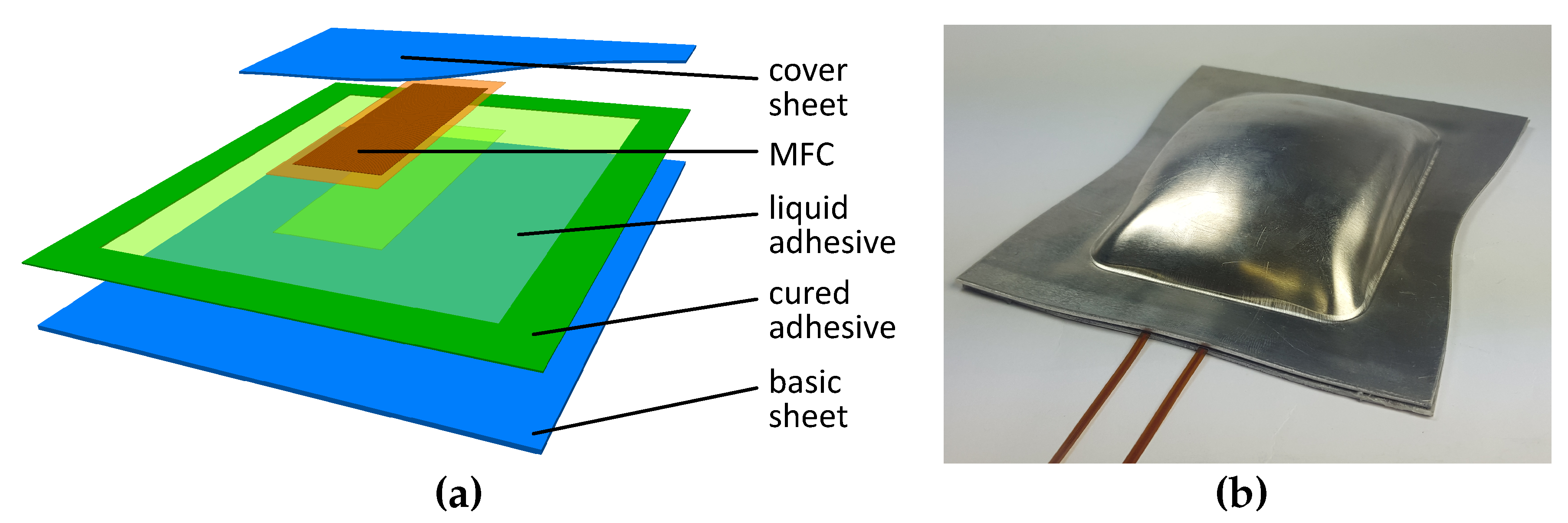
Figure 1a shows the build-up of a piezoceramic-metal compound before it is shaped in a forming operation. The cover sheet metal is partially cut to enhance visibility. The basic sheet metal is covered by the adhesive, whose outer edge is cured, while the inner region remains in its initial liquid state. An MFC is embedded in the middle of the liquid adhesive, covered with a thin liquid film of adhesive on both sides. The compound is closed by the upper cover sheet metal, which may have smaller dimensions than the basic sheet. Hence, the MFC is fully embedded in liquid adhesive, which is then again encapsulated by the circumferential cured adhesive. This enables a closed liquid volume, in which loads, and especially the frictional stresses due to forming, are drastically reduced for the MFC. The encapsulation inhibits adhesive leakage that would contaminate the forming tools. Forming takes place the same as in the conventional process. Figure 1b shows a deep drawing specimen with a punch with a double-curvature radius of 100 . The two contacting electrodes, supplying the MFC with a voltage signal later, have to withstand the forming pressures and frictional stresses between the sheet metals and the tools. Special conductor paths were used, which were individually manufactured for the project. The conducting path is covered by polyimide films on the upper and lower surfaces, which make the wire very durable, resisting even very locally acting pressures. The MFC bearing in liquid adhesive extents formability limits and ensures elastic MFC deformations as far as possible while plastic strains occur in the sheet metals.
2.5. Production Process and Automated Fabrication Unit (AFU)
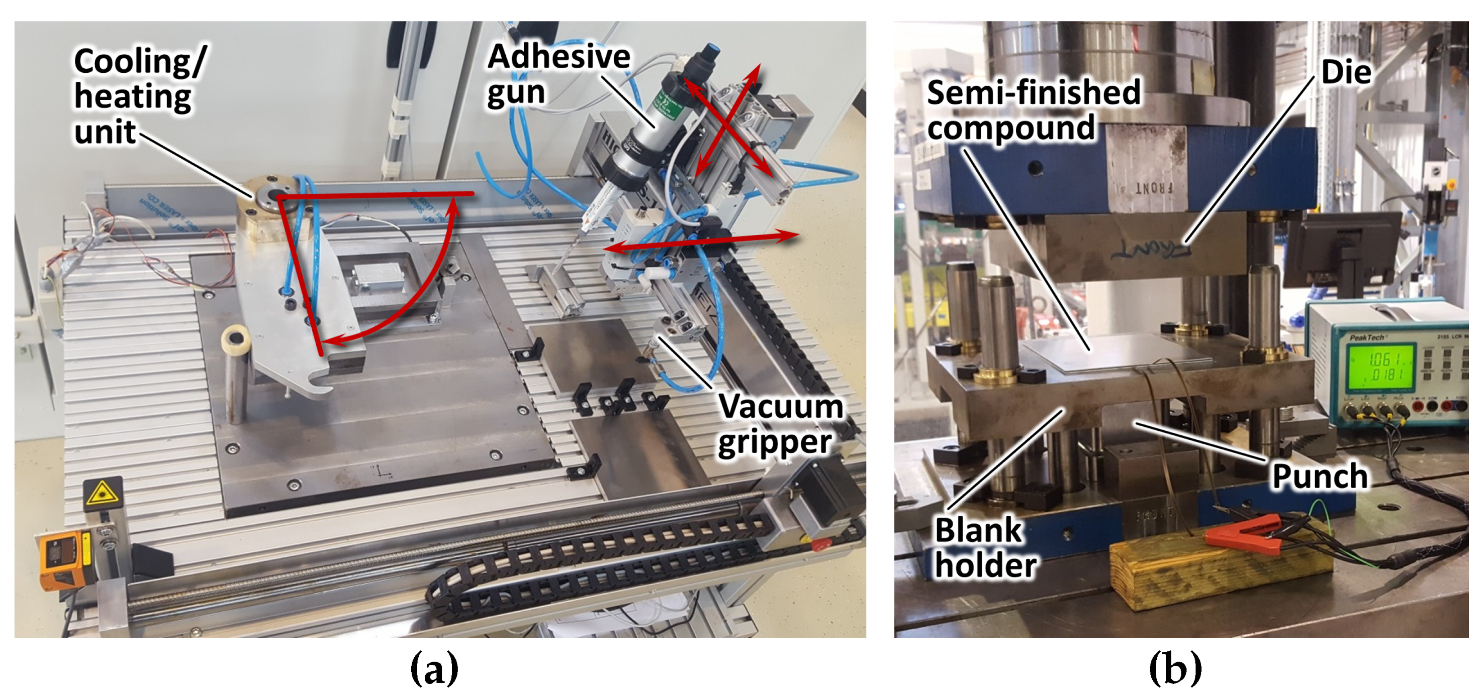
The main difficulty for broad spreading of adaptronic concepts is their integration capability for series production. The present production process utilizing a semi-finished material provides a method to meet the demands of efficient process chains because MFC application is avoided under laboratory conditions. Necessary requirement is an automation of the production process for the semi-finished material. In former studies (e.g., [19]), two different adhesives were used to realize the liquid bearing and the encapsulation by a cured circumferential adhesive. In order to increase the automation capability, only one adhesive system was used in the present study. The adhesive SikaFast 5215 NT by manufacturer Sika is a two-component system (resin and hardener) that is mixed up prior to application. The chemical curing reaction starts and may be accelerated using a thermal treatment. Cooling causes a delay of the curing reaction. This mechanism is used to provide the outer cured region of the semi-finished compound. Therefore, an automatic fabrication unit (AFU) was built up that facilitates automation of the steps sheet-metal handling and positioning, adhesive application, MFC positioning and thermal treatment of the semi-finished compound. Besides time saving, the increase in reproducibility is the main advantage of automation using the AFU. In particular, the adhesive curing process is very sensitive to variations in curing time and temperature, which is inevitable in manual fabrication. Figure 2a depicts the AFU with its components. It consists of a handling/application head, which is mounted on a spindle table. Thus, the head is able to move in all directions. Furthermore, a cooling/heating unit performs the thermal treatment with an outer heated zone (with embedded electric cartridges) and an inner cooling zone (with inner cooling water channels). A corresponding upper unit is rotatable and encloses the compound for the treatment.
In the compound production process, the lower basic sheet metal is first transferred to the cooling/heating unit with the vacuum gripper. Then, the first adhesive layer is applied by the pneumatic gun. After application of the MFC and the second adhesive layer, the cover sheet metal encloses the compound. The upper cooling/heating unit is rotated for the following thermal treatment. The compound center is then cooled, while the outer region is heated. Finally, the semi-finished compound with liquid adhesive core is removed after opening of the rotating cooling/heating unit.
After fabrication of the semi-finished part, the compound is transported into the forming machine. Deep drawing on a servo-electric press is used in the present study. Figure 2b shows the semi-finished compound in the deep drawing tool prior to the forming operation. In the last step after forming, the inner adhesive in the specimen fully cures due to the progressing chemical reaction.
3. Results
3.1. Curing Model
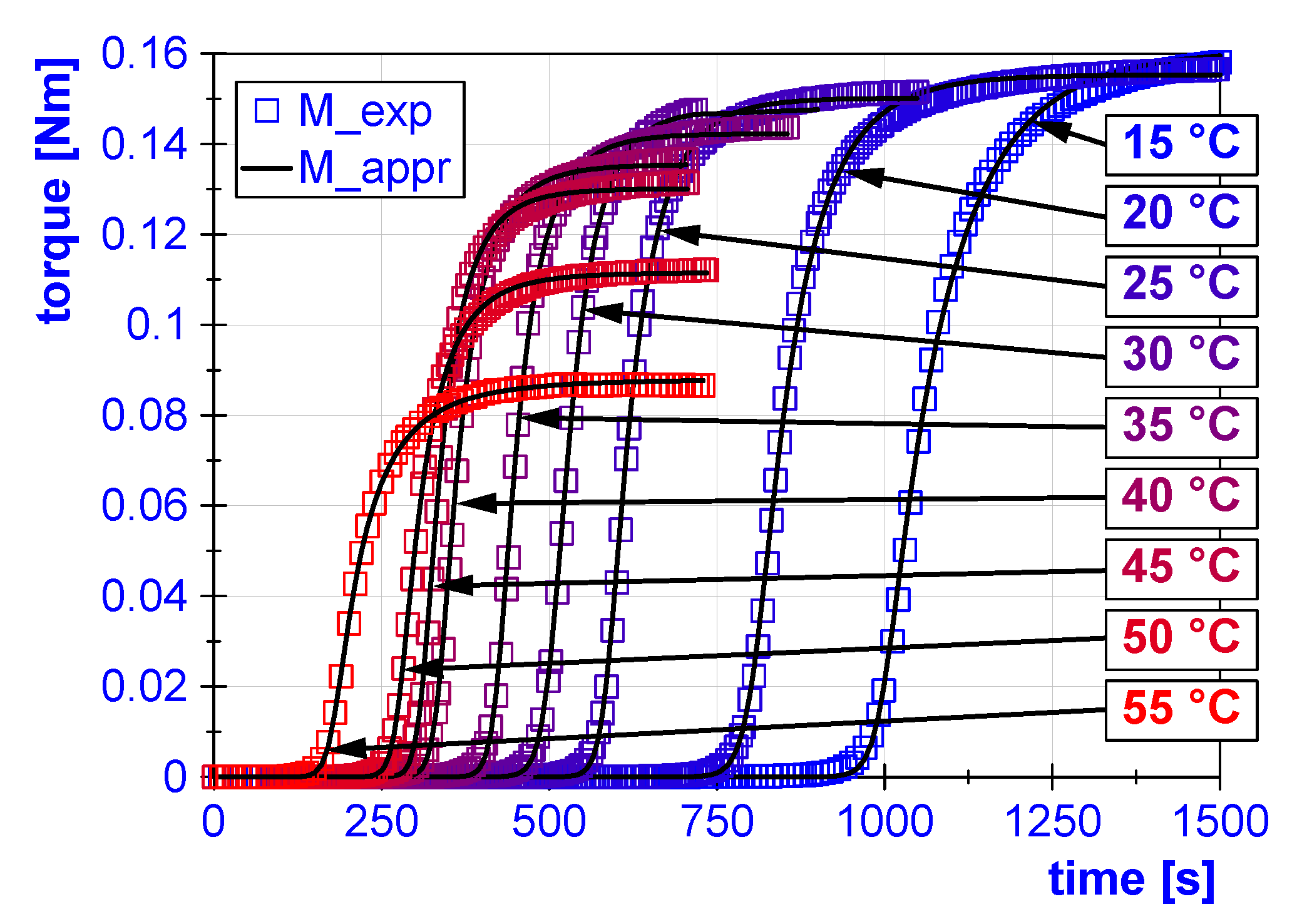
To define the process window for the piezoceramic-metal composite production, a statement is necessary about the assignable loads in the outer heated sheet-metal region. At the same time, the inner cooled region must remain in a liquid state. Hence, the curing behavior of adhesive Sika Fast 5215 NT, used in this study, is investigated with a rotation rheometer Haake Mars 60. The liquid specimen is placed between two removable aluminum plates with a diameter of 20 . An oscillating relative rotation of is then applied during specimen curing. The resulting torque is used to determine the development of storage modulus and loss modulus over time. Three curing tests were carried out for each of nine isothermal temperature steps between 15 °C and 55 .
A model was used that unites the single results to assess the resin curing behavior and to find a feasible process time window. Many authors express the curing kinetics and the resulting mechanical properties of resin with reaction rate and degree of cure. The reaction rate is measured via Differential Scanning Calorimetry (DSC) [20,21,22,23], Fourier Transform Infrared Spectroscopy (FTIR) [24,25], Raman spectroscopy [26,27], Dielectric Analysis (DEA) [28,29,30] or Ultrasonic Cure Monitoring (UCM) [31]. A typical model approach starts with a kinetic differential equation for the degree of cure rate (e.g., [20]), which includes an activation energy formulation of Arrhenius-type. Furthermore, the DiBenedetto equation is often used to include diffusion control. An approach for mechanical properties is developed with the fitted model for degree of cure. Examples for such approaches are based on Prony-series [32], exponential forms [33], or sums of Maxwell elements [34].
For the present study, a proposition is necessary only for the transferable loads. Hence, a simpler model is sufficient, directly linking curing times and temperatures with the actual resin stiffness. An appropriate approach of this kind is described in [35]. The storage modulus is expressed as an integral over curing time t of the storage modulus growth, which is approximated with an exponential function with the parameters: maximum loss modulus , gelation time and fitting coefficients k, (Equation (1)):
The advantage of this approach is the direct input of and from the experiment. One disadvantage is the symmetric exponential form of the equation. The adhesive Sika Fast 5215 NT, used in the present study, shows pronounced differences between start of storage modulus growth and saturation at the end of the reaction. Furthermore, the storage modulus represents only pure elastic portions of the material behavior. However, viscous amounts after gelation, which are measured with the loss modulus, may also conduce to transmissibility of shear. Thus, a measurement of torque was preferred and was carried out with the Haake Mars 60 rotational rheometer. For nine constant temperatures, the adhesive curing is monitored by recording of the torque that results from a constant oscillation loading angle of . An asymmetric phenomenological model is used to describe the increase of torque which mirrors the rise in transferable loads. The torque starts at a very low level and rises drastically when the rate of curing is at a maximum. With increasing linkage, the curing reaction slows down because the mobility of molecular chains is hindered by the increase of the linkage. Similar growth events are described with sigmoidal functions in ecology to model prey/predator relationships with saturation of predator attacks at higher prey density (Holling type III functional response, [36]), bacterial growth in microbiology [37], as activation functions in artificial neurons in computational neuroscience, and probability distributions such as the Weibull distribution. These kinds of equations can be generalized as a non-symmetric non-exponential approach with Equation (2). Here, M denotes the torque, t the curing time and , , , coefficients for curve fitting:
Figure 3 shows plots of experimentally determined torque over time for the nine isothermal temperature steps. The model Equation (2) was fitted to the experimental results with least mean square error optimization. Each fit yields a separate set of coefficients , , and . They are listed in Table 1. The curves are depicted in Figure 3.
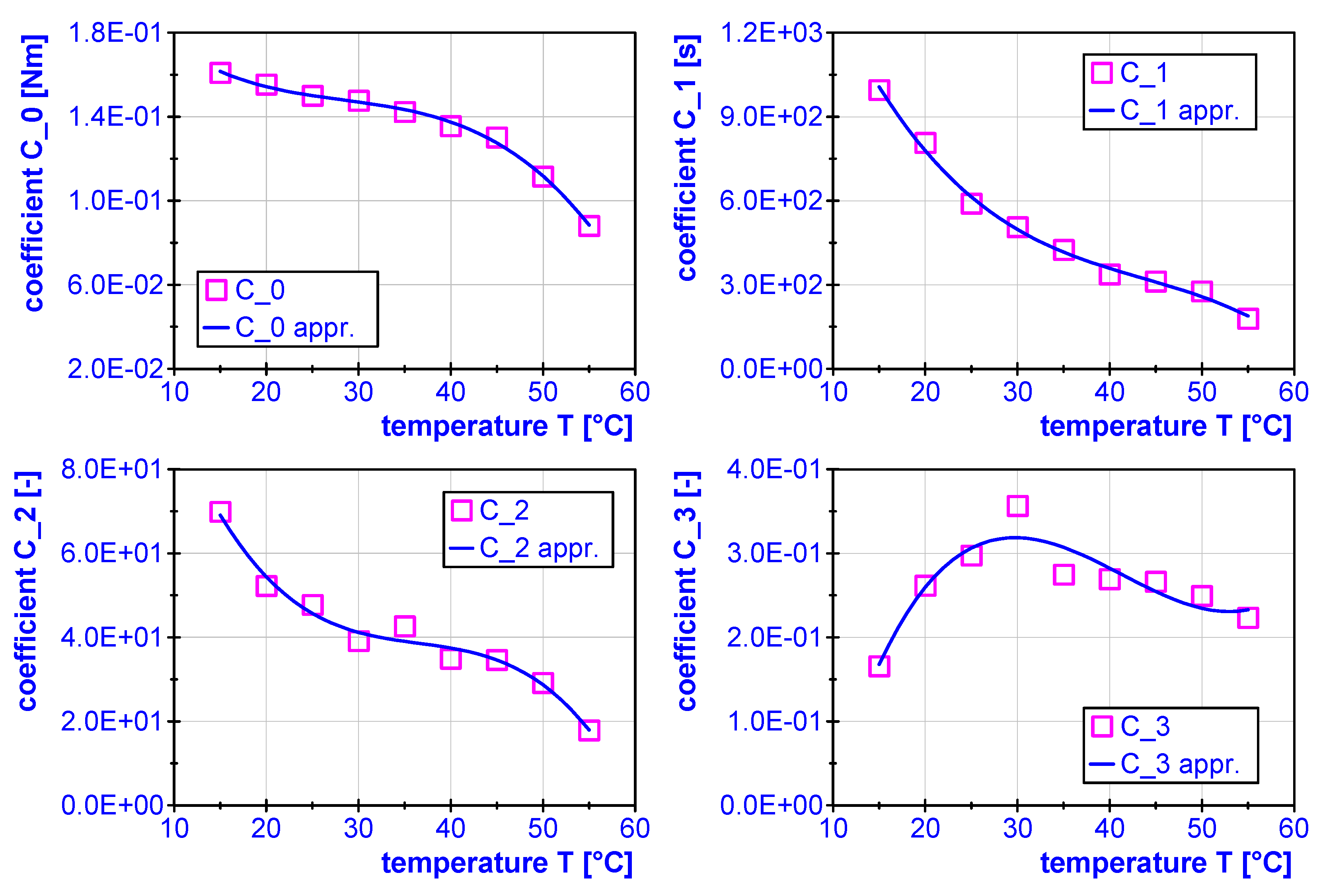
The curve fitting results in consistent sequences of the varied coefficients . Thus, a further approximation for is possible to include the temperature dependency of the curing behavior. Polynomial sum Equation (3) was used to express . Here, denotes the four coefficients later used in Equation (2), the polynomial coefficients used in the present curve fit, T the temperature and j the degree of the polynomial. Again, root mean square error optimization was applied to identify . Table 2 indicates the calculated values for each coefficient , and Figure 4 illustrates the corresponding results of the curve fittings:
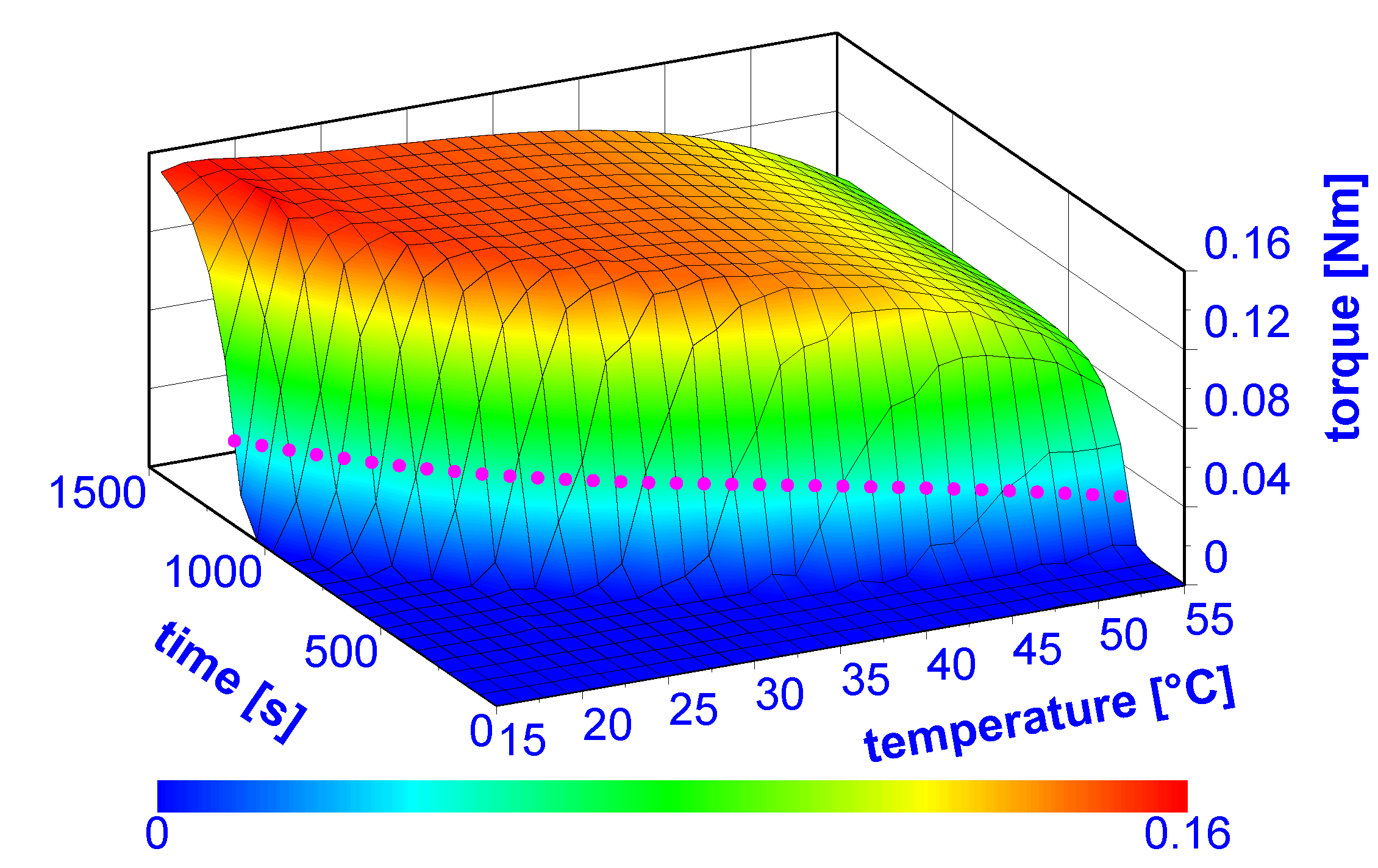
Now, with the identified coefficients , it is possible to model the torque dependent on isothermal temperatures T and curing time t. Figure 5 shows the curing behavior of adhesive SikaFast 5215 NT via necessary torque in the time–temperature space. The temperature dependency holds true only for isothermal temperatures. A change of thermal conditions necessitates usage of a more complex model such as [20].
3.2. Process Window
One aim of the study was the definition of a secure process window in which the inner adhesive remains in liquid condition while providing an outer area with cured adhesive. The gelation point separates the material behavior of the adhesive. Below this point, the material acts more like a fluid, and after the gelation point it behaves like a visco-elastic solid body. However, the material does not change its state abruptly, which is implied by the term “gelation point”. Hence, several methods based on loss modulus or loss factor exist for the determination of gelation [35]. In the present study, the gelation point is defined as the reversal point of torque. At this point, the increase of torque, which is necessary to deform the specimen, is at a maximum. After elastic phases become predominant, the torque further increases, but with a lower slope, which implies that the chemical reaction velocity decreases after maximum torque increase. At this gelation point, the second derivative of torque equals zero:
After rearranging Equation (4), the time at reversal point is obtained. After insertion in Equation (2), the torque at reversal point dependent on temperature reads
with containing the temperature. The resulting three-dimensional curve on the flank of the torque surface is shown as a dotted line in Figure 5.
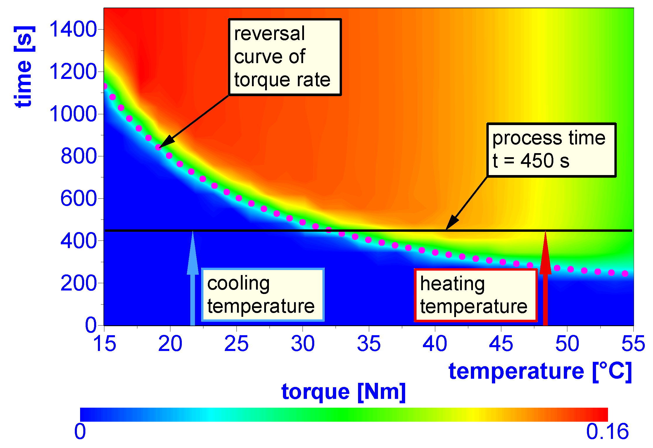
A more quantitative view is illustrated in Figure 6, which shows a contour plot of the torque surface in Figure 5. Again, the dotted line shows the reversal points calculated with Equation (5). The reversal line separates the two regions with fluidic and visco-elastic solid material behavior, respectively. As a result, the optimum start-time for deep drawing can be deduced. At 450 , a heating temperature of 48 leads to a fully cured adhesive while a cooling temperature of 22 maintains an uncured, i.e., liquid material state. Nevertheless, the chemical reaction has started and curing of the cooled adhesive region takes place after the process step of deep drawing.
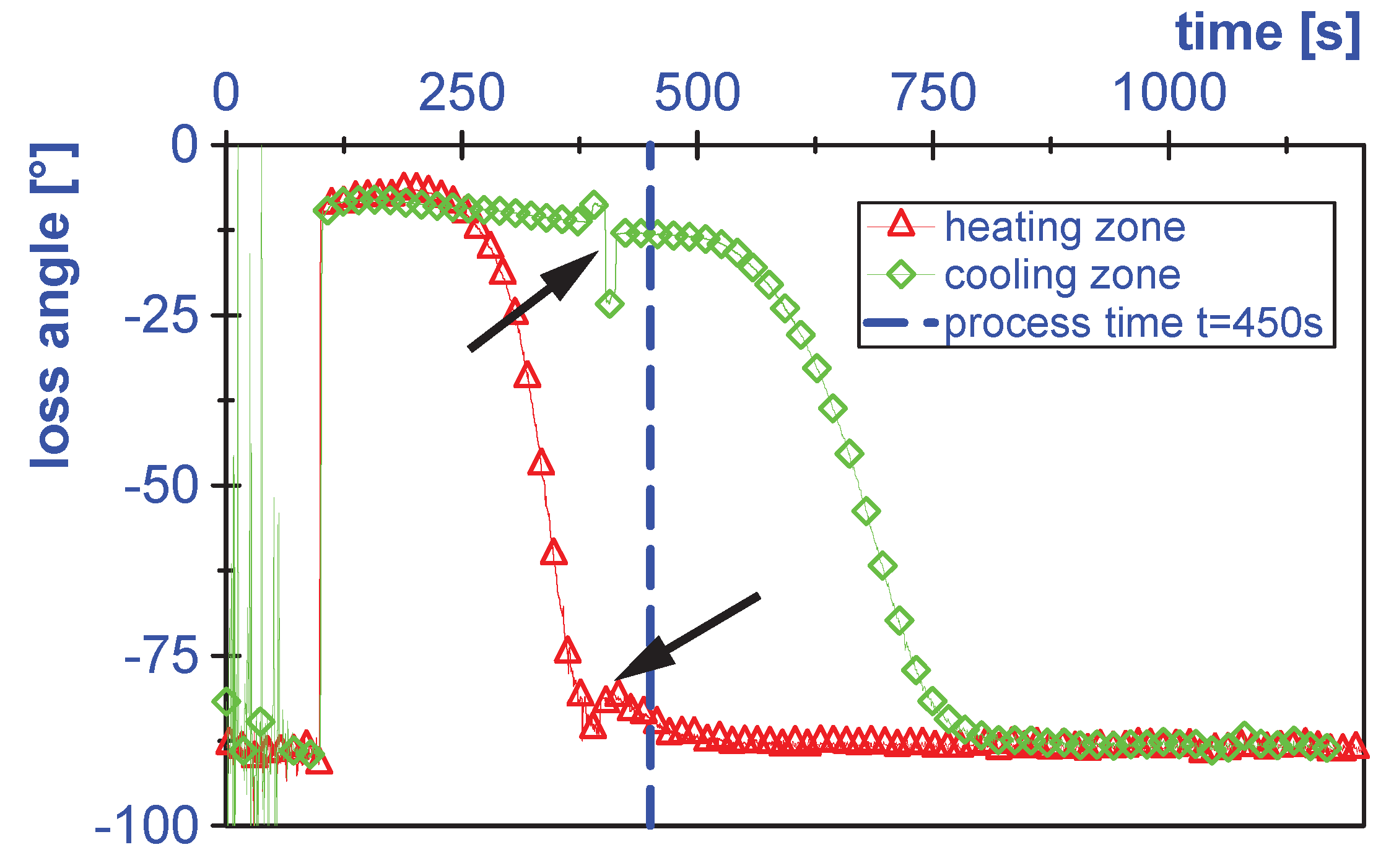
In the next step, the verification of the results was carried out using the AFU to ensure the secure process window under production conditions. For this purpose, DEA was applied to evaluate the state of curing via loss angle measurement. Dielectric sensors were placed between the sheet metals in the liquid adhesive at the outer heated region and the inner cooled position at the specimen center. All production steps were applied skipping the deep drawing stage to avoid breakdown of sensors in the final curing stage. The LCR-meter settings for the measurement were chosen with a frequency of 1 and a voltage of 1 . Figure 7 shows the results for the sensor positions at the outer heated and the inner cooled adhesive zone. The significant acceleration of the chemical reaction resulting in earlier cross-linkage rise results in a sufficient curing state at the outer edges after a process time of 450 . The cooling retards the curing and secures the liquid state in the center of the specimen after 450 . Thus, in further investigations with the chosen temperatures, deep drawing starts in the complete process chain 450 after mixing the resin with the hardener. The opening of the cooling/heating unit on AFU causes a change in pressure and geometry in the adhesive gap, causing a slight peak in the loss angle curves (arrows in Figure 7). Furthermore, at the beginning, the sensors are placed in the adhesive after some handling steps of the AFU. In this lead time, the sensor signals strongly fluctuate until stabilization due to contact with the adhesive.
3.3. Investigation with Automated Process Chain
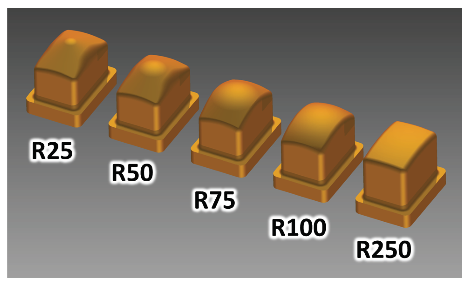
Using the determined process window, it is possible to run the production process within the optimized parameters and directly compare it with a process outside of the window. The worst case includes a long retention time in which the liquid adhesive core of the semi-finished compound is already cured before forming takes place. This leads to a direct transmission of forming loads to the piezoceramic transducer and may cause a reduction of the final part performance. Two investigations were carried out. In the first study, the semi-finished compounds were processed immediately in the following deep-drawing step. In the second study, a retention time of 5 d was added before forming. Several punches with double-curvature radii between 50 and 250 (Figure 8) were used in the deep-drawing tool (Figure 2b) to vary the forming load. Higher radii cause lower loads. However, lower radii can significantly damage the MFC, causing severe crack development in the brittle piezoceramic fibers. In a former study, it was found that the crack density is linearly correlated with the performance loss of the MFC and failure of the final part [38].
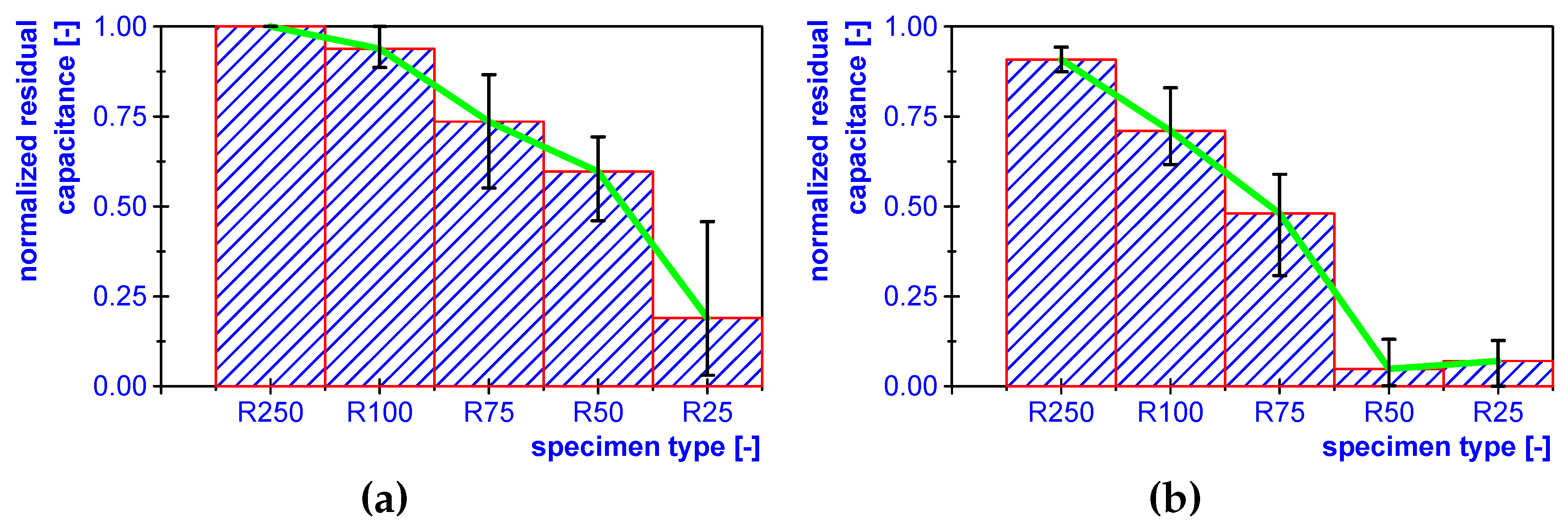
In the tests, the MFC capacitance was measured before and after the forming operation. The overall capacitance of the piezoceramic transducer is often used to evaluate the contacted fiber volume [39], which implies the intact MFC area. The initial capacitance shows scattering. Hence for comparability, a normalized residual capacitance was defined to include the initial and the final state. Each punch configuration was investigated with three specimens. Identical parameters were used for the production of the semi-finished compounds. Figure 9 depicts the results, which are the average of the three tests in the series. The error bars denote minimum and maximum values in the corresponding series. The uninterrupted process (Figure 9a) acts as a reference. As forming loads increase with decreasing punch radii, the residual performance of the part is reduced from 100% with a radius of 250 until it falls below 25% with a radius of 25 . In the case of the cured adhesive (Figure 9b), the residual capacitance starts below 100% in the forming experiment with a punch radius of 250 . All following experiments down to a radius of 25 show a lower residual capacitance than the corresponding test with the uncured adhesive.
4. Discussion and Conclusions
Former studies (e.g., [19]) have shown the feasibility of the liquid bearing concept with an inner uncured adhesive. This significantly improves the manufacturing process. Premise is a high degree of automation in semi-finished part production. In the present study, the process window was investigated for preconditioning of the adhesive. Using cooling and heating elements, the outer adhesive is cured while the inner adhesive remains in a liquid condition, acting as a lubricant in the later shaping process. Determination of process limits was carried out in basic rheological experiments. Linking curing times with torque that is necessary to deform a specimen provides the curing behavior for several isothermal temperatures in time. The curing process is a gradual transition from liquid to the cured condition. Hence, no sharp time limit can be identified. One characteristic point in the curing curve is the gelation point, which is often used to describe the transition. In the present study, it is defined as the time when the torque increase reaches its maximum. By approximation of the curing behavior with a surface equation approach, it is possible to find the continuous second derivatives curve analytically. Now the curing characteristics can be clearly subdivided into two regions: a more liquid and a more elastic adhesive behavior. On the dividing line, the chemical curing reaction is at its maximum. Using the results, a process window is determined for the optimum process. Two process types were compared in a final study: running inside and outside the process window. In the first process, the cooling/heating temperatures and time are set to provide the inner liquid adhesive. After manufacturing the semi-finished part, the final shaping operation was carried out with five punch geometries from punch radius R250, which causes the lowest curvature and implies the smallest loading of the compound, down to R25, which results in the maximum load level. The lubricating adhesive supports the forming process using geometries R250 and R100. When using geometries below R100 with more compound loading, the geometrical loads take over, resulting in a lower residual performance of approx. 75% or less. The semi-finished parts were fully cured in the forming outside of the process window. As a result, the final residual performances are always below the values of the forming inside the process window. Without lubrication, less than 75% residual performance are reached with punch geometry R100. Performance consistently decreases in this process. The differences in results are not too high, but using a liquid inner adhesive enables a forming operation without performance degradation.
With the automated semi-finished part production, a robust and reproducible process was designed. Furthermore, a method is presented for determination of the process limits in piezoceramic compound production. Alternative adhesive systems can be characterized. The direct comparison with a process running outside of the process window shows the necessity of lubrication via a liquid adhesive. Further research will focus on usage of alternative adhesives, further process time reduction and on implementation of extended automatic process control such as adaption of adhesive application velocity and thermal treatment.
Author Contributions
Conceptualization, M.N. and S.H.; Methodology, M.N. and S.H.; Validation, S.H.; Investigation S.H.; Writing—Original Draft Preparation, S.H.; Writing—Review and Editing, S.H., M.N. and W.-G.D.; Visualization, S.H.; Software, S.H.; Project Administration, W.-G.D.; Funding Acquisition, W.-G.D., M.N. and S.H.
Funding
This research was funded by Deutsche Forschungsgemeinschaft (DFG) Grant No. 29243924 (Collaborative Research Centre/Transregio 39 PT-PIESA, subproject B01).
Conflicts of Interest
The authors declare no conflict of interest. The founding sponsors had no role in the design of the study; in the collection, analyses, or interpretation of data; in the writing of the manuscript, and in the decision to publish the results.
Abbreviations
The following abbreviations are used in this manuscript:
| DEA | Dielectric analysis |
| MFC | Macro fiber composite |
| AFU | Automated fabrication unit |
References
- Suleman, A.; Prasad, E.; Blackow, R.; Waechter, D. Smart Structures—An Overview. In Smart Structures: Applications and Related Technologies; Suleman, A., Ed.; Springer Verlag: Wien, Austria, 2001; pp. 3–16. [Google Scholar] [CrossRef]
- Bekas, D.G.; Sharif-Khodaei, Z.; Aliabadi, M.F. An Innovative Diagnostic Film for Structural Health Monitoring of Metallic and Composite Structures. Sensors 2018, 18, 2084. [Google Scholar] [CrossRef]
- Park, G.; Farrar, C.R.; di Scalea, F.L.; Coccia, S. Performance assessment and validation of piezoelectric active-sensors in structural health monitoring. Smart Mater. Struct. 2006, 15, 1673–1683. [Google Scholar] [CrossRef]
- Arrieta, A.F.; van Gemmeren, V.; Anderson, A.J.; Weaver, P.M. Dynamics and control of twisting bi-stable structures. Smart Mater. Struct. 2018, 27, 025006. [Google Scholar] [CrossRef] [Green Version]
- Asundi, A.; Choi, A.Y. Fiber metal laminates: An advanced material for future aircraft. J. Mater. Process. Technol. 1997, 63, 384–394. [Google Scholar] [CrossRef]
- Botelho, E.C.; Silva, R.A.; Pardini, L.C.; Rezende, M.C. A review on the development and properties of continuous fiber/epoxy/aluminum hybrid composites for aircraft structures. Mater. Res. 2006, 9, 247–256. [Google Scholar] [CrossRef] [Green Version]
- Burchitz, I.; Boesenkool, R.; van der Zwaag, S.; Tassoul, M. Highlights of designing with Hylite—A new material concept. Mater. Des. 2005, 26, 271–279. [Google Scholar] [CrossRef]
- Palkowski, H.; Lange, G. Austenitic Sandwich Materials in the Focus of Research. In Proceedings of the 2nd International Conference Deformation Processing and Structure of Materials, Belgrade, Serbia, 26–28 May 2005; pp. 19–27. [Google Scholar]
- Palkowski, H.; Giese, P.; Wesling, V.; Lange, G.; Spieler, S.; Göllner, J. Neuartige Sandwichverbunde—Herstellung, Umformverhalten, Fügen und Korrosionsverhalten. Materialwiss. Werkstofftechn. 2006, 37, 605–612. [Google Scholar] [CrossRef]
- Stegmaier, T.; Hager, T.; Yilmaz, D.; Vohrer, A.; Sürth, M.; Planck, H.; Wagner, S.; Becker, D.; Hahn, O.; Teutenberg, D. Stahlblech-Mehrschichtverbund mit textiler Einlage. Werkstattstech. Online 2008, 10, 866–870. [Google Scholar]
- Sexton, A.; Cantwell, W.; Kalyanasundaram, S. Stretch forming studies on a fibre metal laminate based on a self-reinforcing polypropylene composite. Compos. Struct. 2012, 94, 431–437. [Google Scholar] [CrossRef]
- Jackson, K.; Allwood, J.; Landert, M. Incremental forming of sandwich panels. J. Mater. Process. Technol. 2008, 204, 290–303. [Google Scholar] [CrossRef]
- Palkowski, H.; Lange, G. Creation of Tailored High-Strength, Hybrid Sandwich Structures. Adv. Mater. Res. 2007, 22, 27–36. [Google Scholar] [CrossRef]
- Sokolova, O.; Carradó, A.; Palkowski, H. Production of customized high-strength hybrid sandwich structures. Adv. Mater. Res. 2010, 137, 81–128. [Google Scholar] [CrossRef]
- Nestler, M.; Drossel, W.G.; Hensel, S.; Müller, R. Fabrication Method for Series Production of Sheet Metal Parts with Integrated Piezoelectric Transducers. Procedia Technol. 2014, 15, 494–502. [Google Scholar] [CrossRef] [Green Version]
- SikaFast®-5215 NT—Fast Curing, Two-Part Structural Adhesive; Version 1; Sika Schweiz AG: Zürich, Switzerland, 2013.
- Müller, M.; Müller, B.; Hensel, S.; Nestler, M.; Jahn, S.; Wittstock, V.; Schubert, A.; Drossel, W.G. Structural Integration of PZT Fibers in Deep Drawn Sheet Metal for Material-integrated Sensing and Actuation. Procedia Technol. 2014, 15, 658–667. [Google Scholar] [CrossRef]
- Thielicke, B.; Gesang, T.; Wierach, P. Reliability of piezoceramic patch sensors under cyclic mechanical loading. Smart Mater. Struct. 2003, 12, 993–996. [Google Scholar] [CrossRef]
- Drossel, W.G.; Müller, R.; Nestler, M.; Hensel, S. Integration in Sheet Metal Structures. In Material-Integrated Intelligent Systems—Technology and Applications; Wiley-Blackwell: Hoboken, NJ, USA, 2017; Chapter 8; pp. 201–216. [Google Scholar] [CrossRef]
- Kamal, M.R.; Sourour, S. Kinetics and thermal characterization of thermoset cure. Polym. Eng. Sci. 1973, 13, 59–64. [Google Scholar] [CrossRef]
- Sourour, S.; Kamal, M. Differential scanning calorimetry of epoxy cure: Isothermal cure kinetics. Thermochim. Acta 1976, 14, 41–59. [Google Scholar] [CrossRef]
- Lee, W.I.; Loos, A.C.; Springer, G.S. Heat of Reaction, Degree of Cure, and Viscosity of Hercules 3501-6 Resin. J. Compos. Mater. 1982, 16, 510–520. [Google Scholar] [CrossRef]
- Fereshteh-Saniee, N.; Reynolds, N.; Kelly, C.A.; Wilson, P.R.; Jenkins, M.J.; Kendall, K.N. Introducing Cryomilling for Reliable Determination of Resin Content and Degree of Cure in Structural Carbon Fibre Reinforced Thermoset Composites. Compos. Part A 2018. [Google Scholar] [CrossRef]
- Ferracane, J.; Condon, J. Post-cure heat treatments for composites: Properties and fractography. Dent. Mater. 1992, 8, 290–295. [Google Scholar] [CrossRef]
- Czasch, P.; Ilie, N. In vitro comparison of mechanical properties and degree of cure of bulk fill composites. Clin. Oral Investig. 2013, 17, 227–235. [Google Scholar] [CrossRef] [PubMed]
- Lyon, R.E.; Chike, K.E.; Angel, S.M. In situ cure monitoring of epoxy resins using fiber-optic Raman spectroscopy. J. Appl. Polym. Sci. 1994, 53, 1805–1812. [Google Scholar] [CrossRef]
- Hardis, R.; Jessop, J.L.; Peters, F.E.; Kessler, M.R. Cure kinetics characterization and monitoring of an epoxy resin using DSC, Raman spectroscopy, and DEA. Compos. Part A 2013, 49, 100–108. [Google Scholar] [CrossRef]
- Bang, K.G.; Kwon, J.W.; Lee, D.G.; Lee, J.W. Measurement of the degree of cure of glass fiber–epoxy composites using dielectrometry. J. Mater. Process. Technol. 2001, 113, 209–214. [Google Scholar] [CrossRef]
- Sernek, M.; Kamke, F.A. Application of dielectric analysis for monitoring the cure process of phenol formaldehyde adhesive. Int. J. Adhes. Adhes. 2007, 27, 562–567. [Google Scholar] [CrossRef]
- Steinhaus, J.; Hausnerova, B.; Haenel, T.; Großgarten, M.; Möginger, B. Curing kinetics of visible light curing dental resin composites investigated by dielectric analysis (DEA). Dent. Mater. 2014, 30, 372–380. [Google Scholar] [CrossRef]
- White, S.R.; Mather, P.T.; Smith, M.J. Characterization of the cure-state of DGEBA-DDS epoxy using ultrasonic, dynamic mechanical, and thermal probes. Polym. Eng. Sci. 2002, 42, 51–67. [Google Scholar] [CrossRef]
- O’Brien, D.J.; Mather, P.T.; White, S.R. Viscoelastic Properties of an Epoxy Resin during Cure. J. Compos. Mater. 2001, 35, 883–904. [Google Scholar] [CrossRef] [Green Version]
- Hsich, H.S.Y. Kinetic model of cure reaction and filler effect. J. Appl. Polym. Sci. 1982, 27, 3265–3277. [Google Scholar] [CrossRef]
- Simon, S.L.; Mckenna, G.B.; Sindt, O. Modeling the evolution of the dynamic mechanical properties of a commercial epoxy during cure after gelation. J. Appl. Polym. Sci. 2000, 76, 495–508. [Google Scholar] [CrossRef]
- Kashani, P.; Minaie, B. An ex-situ state-based approach using rheological properties to measure and model cure in polymer composites. J. Reinf. Plast. Compos. 2011, 30, 123–133. [Google Scholar] [CrossRef]
- Holling, C.S. The Components of Predation as Revealed by a Study of Small-Mammal Predation of the European Pine Sawfly. Can. Entomol. 1959, 91, 293–320. [Google Scholar] [CrossRef]
- Zwietering, M.H.; Jongenburger, I.; Rombouts, F.M.; van’t Riet, K. Modeling of the Bacterial Growth Curve. Appl. Environ. Microbiol. 1990, 56, 1875–1881. [Google Scholar] [PubMed]
- Drossel, W.G.; Hensel, S.; Nestler, M.; Müller, R. Method for Large-Scale Production of Piezoceramic-Metal-Compounds. Adv. Eng. Mater. 2018. [Google Scholar] [CrossRef]
- Sodano, H.A.; Lloyd, J.; Inman, D.J. An experimental comparison between several active composite actuators for power generation. Smart Mater. Struct. 2006, 15, 1211. [Google Scholar] [CrossRef]
Figure 1.
(a) exploded view of a piezoceramic-metal compound before forming and (b) complex-shaped structural part with integrated actuator/sensor functionality after forming.
Figure 1.
(a) exploded view of a piezoceramic-metal compound before forming and (b) complex-shaped structural part with integrated actuator/sensor functionality after forming.

Figure 2.
(a) automated fabrication unit (AFU) with rotatable upper and fixed lower cooling/heating unit on the left side and handling/application head with gripper and adhesive gun on the right side of the picture and (b) semi-finished compound before forming in the deep-drawing tool.
Figure 2.
(a) automated fabrication unit (AFU) with rotatable upper and fixed lower cooling/heating unit on the left side and handling/application head with gripper and adhesive gun on the right side of the picture and (b) semi-finished compound before forming in the deep-drawing tool.

Figure 3.
Curing behavior of adhesive SikaFast 5215 NT and approximation.

Figure 4.
Visualization of approximation of coefficients , describing the curing behavior of adhesive SikaFast 5215 NT.
Figure 4.
Visualization of approximation of coefficients , describing the curing behavior of adhesive SikaFast 5215 NT.

Figure 5.
Approximation model for curing behavior of adhesive SikaFast 5215 NT.

Figure 6.
Process paths for cooling and heating location in the contour plot of torque.

Figure 7.
Loss angle measurement at the outer heated location and at the inner cooled position. The dashed line marks the aimed deep drawing start-time at 450 . The arrows mark discontinuities in the curves resulting from AFU processing.
Figure 7.
Loss angle measurement at the outer heated location and at the inner cooled position. The dashed line marks the aimed deep drawing start-time at 450 . The arrows mark discontinuities in the curves resulting from AFU processing.

Figure 8.
Punches used in the deep-drawing process to vary the forming loads. Double-curvature radius of 250 (R250) causes the lowest load in the deep-drawing process.
Figure 8.
Punches used in the deep-drawing process to vary the forming loads. Double-curvature radius of 250 (R250) causes the lowest load in the deep-drawing process.

Figure 9.
Normalized residual capacitance after deep drawing (a) inside the process window and (b) outside the process window.
Figure 9.
Normalized residual capacitance after deep drawing (a) inside the process window and (b) outside the process window.


Table 1.
Fitting coefficients of Equation (2) for different temperature sets.
| T [C] | [N m] | [s] | [-] | [-] |
|---|---|---|---|---|
| 15 | 1.61 × 10⁻¹ | 9.96 × 10² | 6.99 × 101 | 1.66 × 10⁻¹ |
| 20 | 1.55 × 10⁻¹ | 8.07 × 10² | 5.22 × 101 | 2.61 × 10⁻¹ |
| 25 | 1.50 × 10⁻¹ | 5.90 × 10² | 4.77 × 101 | 2.97 × 10⁻¹ |
| 30 | 1.48 × 10⁻¹ | 5.06 × 10² | 3.91 × 101 | 3.56 × 10⁻¹ |
| 35 | 1.42 × 10⁻¹ | 4.25 × 10² | 4.26 × 101 | 2.75 × 10⁻¹ |
| 40 | 1.36 × 10⁻¹ | 3.38 × 10² | 3.49 × 101 | 2.69 × 10⁻¹ |
| 45 | 1.30 × 10⁻¹ | 3.12 × 10² | 3.46 × 101 | 2.66 × 10⁻¹ |
| 50 | 1.12 × 10⁻¹ | 2.77 × 10² | 2.91 × 101 | 2.49 × 10⁻¹ |
| 55 | 0.88 × 10⁻¹ | 1.79 × 10² | 1.79 × 101 | 2.23 × 10⁻¹ |
Table 2.
Fitting coefficients of Equation (3) for different coefficients .
| i | ||||
|---|---|---|---|---|
| 0 | 1.999995 × 10⁻⁴ | −2.343313 × 10⁻⁶ | ||
| 1 | ||||
| 2 | ||||
| 3 |
© 2019 by the authors. Licensee MDPI, Basel, Switzerland. This article is an open access article distributed under the terms and conditions of the Creative Commons Attribution (CC BY) license (http://creativecommons.org/licenses/by/4.0/).
Share and Cite
MDPI and ACS Style
Drossel, W.-G.; Nestler, M.; Hensel, S. Development of Steps in an Automated Process Chain for Piezoceramic-Metal Compound Production. J. Manuf. Mater. Process. 2019, 3, 3. https://doi.org/10.3390/jmmp3010003
AMA Style
Drossel W-G, Nestler M, Hensel S. Development of Steps in an Automated Process Chain for Piezoceramic-Metal Compound Production. Journal of Manufacturing and Materials Processing. 2019; 3(1):3. https://doi.org/10.3390/jmmp3010003
Chicago/Turabian StyleDrossel, Welf-Guntram, Matthias Nestler, and Sebastian Hensel. 2019. "Development of Steps in an Automated Process Chain for Piezoceramic-Metal Compound Production" Journal of Manufacturing and Materials Processing 3, no. 1: 3. https://doi.org/10.3390/jmmp3010003