Influence of Shot Peening on AlSi10Mg Parts Fabricated by Additive Manufacturing


Department of mechanical engineering, McMaster University, 1280 Main Street West Hamilton, Hamilton, ON L8S 4L7, Canada; [email protected]
*
Authors to whom correspondence should be addressed.
J. Manuf. Mater. Process. 2018, 2(3), 40; https://doi.org/10.3390/jmmp2030040
Submission received: 29 May 2018
/
Revised: 11 June 2018
/
Accepted: 22 June 2018
/
Published: 24 June 2018
(This article belongs to the Special Issue Additive Manufacturing)
Abstract
:The additive manufacturing (AM) of aluminum alloys promises to considerably enhance the performance of lightweight critical parts in various industrial applications. AlSi10Mg is one of the compatible Al alloys used in the selective laser melting of lightweight components. However, the surface defects obtained from the as-built parts affect their mechanical properties, and thus represent an obstacle to using them as final products. This study aims to improve the surface characteristics of the as-built AlSi10Mg parts using shot peening (SP). To achieve this goal, different SP intensities were applied to various surface textures of the as-built samples. The SP results showed a significant improvement in the as-built surface topography and a higher value of effective depth using 22.9 A intensity and Gp165 glass beads. The area near the shot-peened surface showed a significant microstructure refinement to a specific depth due to the dynamic precipitation of nanoscale Si particles. Surface hardening was also detected and high compressive residual stresses were generated due to severe plastic deformation. The surface characteristics obtained after SP could result in a significant improvement in the mechanical properties and fatigue strength, and thus promise performance enhancement for critical parts in various industrial applications.
1. Introduction
Additive manufacturing (AM) produces a significant improvement in parts’ performance by achieving design flexibility and weight reduction. AM can be used for the production of a wide range of industrial applications, such as in biomedical, automotive, aerospace, and military fields, and beyond. A selective laser melting (SLM) process is often used for the AM of metals such as Al alloys. AlSi10Mg is one of the most frequently used Al alloys for SLM due to its lower coefficient of thermal expansion (CTE), as compared to that of Al6061, which is commonly used in conventional techniques. The relatively low CTE of AlSi10Mg results in higher dimensional accuracy, superior mechanical properties, and the elimination of crack formation [1]. However, the as-built parts produced could have surface and microstructure defects. This represents an obstacle to achieving high surface quality and consistent mechanical properties. Surface defects, such as porosity and balling formation, considerably affect a part’s quality [2]. The porosity may exist on the surface, or inside the material in the form of keyhole, spherical, or micro shrinkage pores [3]. Spherical balls may also form on the part surface due to the failure of wetting the underlying substrate by the molten material [3].
The improvement of the surface integrity of as-built parts fabricated using SLM is still an active research issue. Calignano et al. [4] illustrated the effect of SLM process parameters on the surface roughness of AlSi10Mg components. Their results showed that laser scan speed is the most significant parameter that affects the surface roughness of as-built parts. Townsend et al. [5] reported that the side and top surfaces of the as-built AlSi10Mg parts have different values of surface roughness due to the disappearance of laser tracks on the side surface. The as-built AlSi10Mg microstructure also showed an inhomogeneity, resulting in an anisotropic structure [6]. Moreover, fatigue, fretting fatigue, wear, and corrosion are considered to be the most common failures of engineering materials to withstand their propagation inside the part [7]. Consequently, the surface treatment of as-built AM parts is required to improve their surface integrity and mechanical properties. Shot peening (SP) is one surface treatment technique that can be used to enhance the surface roughness [5] and improve the fatigue performance of Al alloys [8]. SP is a cold working process that bombards the part surface with spherical beads using high pressure [9]. SP results in a surface layer plastic deformation that generates residual compressive stress due to the application of multiple shot impacts on the part surface [10]. Various studies have reported that SP could improve the hardness, fatigue strength, and tensile strength of the part surface of conventional materials, such as Al alloys [11,12] and Ti6Al4V [13]. The main process parameters of SP are the Almen intensity and surface coverage [14]. First, the Almen intensity represents the arc height calculated from a shot-peened Almen strip due to the incident kinetic energy generated on the sample surface from the shots’ impact [15]. The Almen intensity reflects the effect of the shot size, hardness, speed, flow rate, and impact angle [10]. Qandil et al. [16] reported that the SP intensity applied to Al 7075 T6 and Al 2024 T3 has to be optimized using a relatively small shot size to avoid surface damage by over-peening. Second, the surface coverage represents the ratio of the area covered by the shots’ indentations, as compared to the total area of the surface treated. The surface roughness of the SP part improves along with the increase of surface coverage, until stabilizing at a constant value [14].
Recent studies have focused on applying SP to as-built AM parts to improve their surface finish and wear resistance. Calignano et al. [4] studied the effect of SP using glass beads on the surface roughness of as-built AlSi10Mg parts fabricated through different AM process parameters, in addition to applying various SP pressures. Their results showed a significant reduction in the roughness of as-built surfaces from 76% to 83% using 8 bar pressure. AlMangour et al. [17] reported that SP improves the surface roughness, hardness, fatigue, and yield strength of additively manufactured 17-4 stainless steel. Damon et al. [18] also studied the effect of SP on the porosity formed inside AlSi10Mg parts. They showed that SP using S170 steel beads reduces the porosity by 0.1–0.3% and increases the fatigue strength of the as-built parts. Uzan et al. [19] investigated the influence of SP on the fatigue resistance of AlSi10Mg using steel and ceramic beads. They showed that the mechanical or electrolytic polishing after shot peening could increase the material fatigue resistance. Regarding the aforementioned studies, the impact of SP intensity on microstructure, microhardness, and surface waviness using glass beads has not been fully characterized for both the as-built and machined AlSi10Mg parts fabricated by SLM.
The current study aimed to investigate the influence of SP intensity by examining the surface integrity and the microstructure transformation to satisfy the design requirements of the end user products. SP was applied to different surface textures of as-built AlSi10Mg parts to compare its impact on their surface roughness and waviness, microstructure, microhardness, and residual stress. Different SP intensities were also applied to both as-built and machined surfaces using different glass beads sizes. A full characterization of the surface topography and microstructure was presented after SP, as compared to as-built and machined surfaces. Finally, the microhardness and residual stress profiles were illustrated along the depth of the sample surface.
2. Experimental Procedure
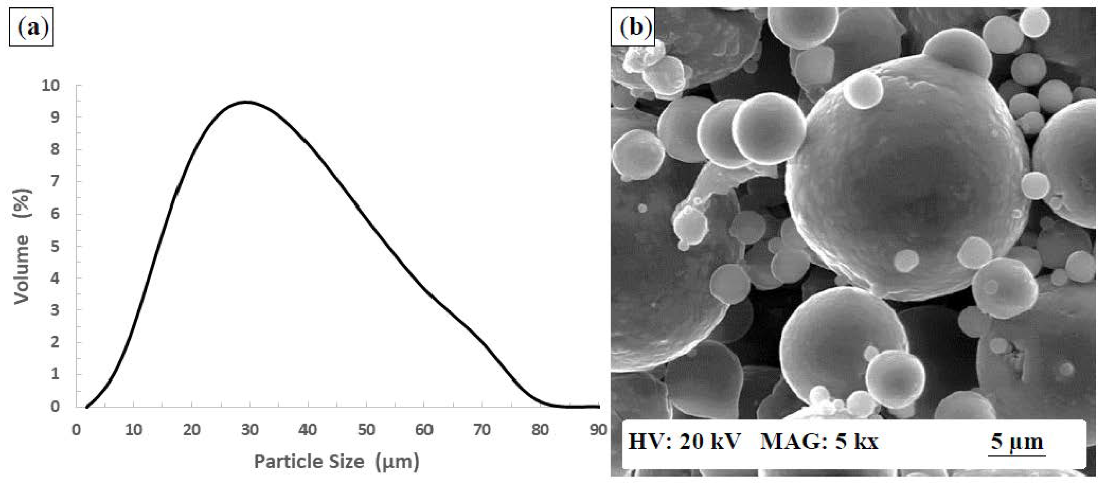
AlSi10Mg powder was used to fabricate the as-built AlSi10Mg samples fabricated by SLM using an EOS M290 machine. This machine is equipped with a fiber laser system up to 400 W power level using a 100-µm spot diameter. A Master Sizer 2000 particle size distribution (PSD) tester, TESCAN VP scanning electron microscope (SEM), and energy dispersive X-ray spectroscopy (EDS) were used for the powder characterization according to ASTM F3049-14 [20]. The PSD of the AlSi10Mg powder was shown to range between 2 µm to 70 µm, as shown in Figure 1a, while D(0.1), D(0.5), and D(0.9) are 11.77, 28.04, and 54.09 µm, respectively. The SEM image in Figure 1b shows the spherical shapes of the powder particles used, and its chemical composition was measured using EDS, as listed in Table 1. The in-core and up-skin process parameters are presented in Table 2 [6]. During the SLM process, argon was used as an inert gas medium to avoid oxidation and hazards within less than 0.1% oxygen. The platform was also preheated to 200 °C before starting the build, in order to control the thermal gradient between the layers to reduce the formation of residual thermal stress. Two sets of AlSi10Mg samples were fabricated with dimensions of 50 mm in diameter and 10 mm in height. The first set represents the as-built strip (AB (strip)) samples, which were produced using in-core parameters. The surface of the second set of samples was fabricated using the up-skin parameters within a thickness of 90 µm. One half of each as-built sample surface was machined using an OKUMA CNC Crown L1060 three-axis machine. A 50-mm cutter diameter was used for face milling at a 100-µm depth of cut using liquid coolant with 350 mm/min cutting speed, 0.03 mm/tooth, and 4000 rpm tool rotation.
SP was applied on the as-built AlSi10Mg samples using a Lance machine equipped with a single nozzle with a 19-mm diameter. Two different Almen intensities were conducted on the machined surface (M), depending on the size of the glass beads used. The high-intensity SP (HSP) was 22.9 A using Gp165 glass beads, while the low-intensity SP (LSP) was 20.3 N using Gp50 glass beads. A coverage surface factor of 200% was applied to avoid the existence of not-peened areas. The distance from the nozzle to the sample surface was 152 mm using a 90-degree angle of impact. As shown in Figure 2, each sample surface was divided into four quarters that had different texture zones, including: as-built (AB), as-built SP (AB + SP), machined (M), high-intensity SP (HSP), and low-intensity SP (LSP).
An Alicona Infinite Focus G5 microscope was used to investigate the surface integrity of the selected areas regarding both surface roughness and waviness measurements. The measured area represents a 10 × 10 mm using a 10× magnification lens. The samples were wire-cut to investigate the microstructure change along their cross-sections. Polishing and etching procedures were applied according to the tuned steps for additively manufactured AlSi10Mg samples, as illustrated by Maamoun et al. [6]. The microstructure was evaluated using the SEM, a Nikon LV100 optical microscope, and a Bruker D8 DISCOVER equipped with a cobalt sealed tube source for the X-ray diffraction (XRD) measurements. The analysis of the FWHM (full width at half maximum) was performed using TOPAS software to investigate the effect of SP on the crystallite size and grain refinement on the surface. An automatic Clemex CMT microhardness tester was used to investigate the surface microhardness, in addition to mapping the microhardness profile in depth. Each of the registered values represents an average of five indentations using a load of 25 gf. The standard deviation for the microhardness measurements was ±2 HV, according to the instrument calibration. The normal residual stress on the surfaces was measured using XRD and analyzed using LEPTOS software, in addition to plotting the residual stress profile in depth from the sample surface.
3. Results and Discussion
3.1. Surface Topography
Figure 3a shows the SEM observations of surface defects of the as-built AlSi10Mg sample, which negatively affect its surface integrity. These defects are represented in balling, partially melted powder, signs of the laser scan track, and surface porosity. Figure 3b illustrates the ellipsoidal balling that formed due to the failure of the melted powder to wet the underlying substrate. This resulted in the formation of either ellipsoidal or spherical balls. The mechanism of balling formation indicates that the energy density is only sufficient to melt the powder particles, but not sufficient to penetrate and thus join the particles with the underlying substrate [21]. The scan speed is also considered to be a significant parameter affecting the balls’ formation upon the surface, and it has the same microstructure of the as-built part [22]. Figure 3c shows satellites that represent partially melted powder particles or spattering particles that were adhered to the sample surface without melting due to their existence inside the heat-affected zone. These particles keep the original microstructure of powder, and they do not have the same microstructure as the as-built part [23]. The track of the strip laser scan is illustrated in Figure 3d. It is the high cooling rate applied to the final layer that makes the texture of these tracks appear; the width of the tracks is slightly larger than the laser beam diameter (100 µm). Figure 3e also illustrates a pore that was formed on the as-built surface that might have developed due to the lack of fusion, or the failure of the molten metal to fill in the whole surface as a result of the balling formation. SP was selected as a cold working post-processing method to try to eliminate the adverse effect of these defects on the surface integrity and to improve the mechanical properties of the part surface.
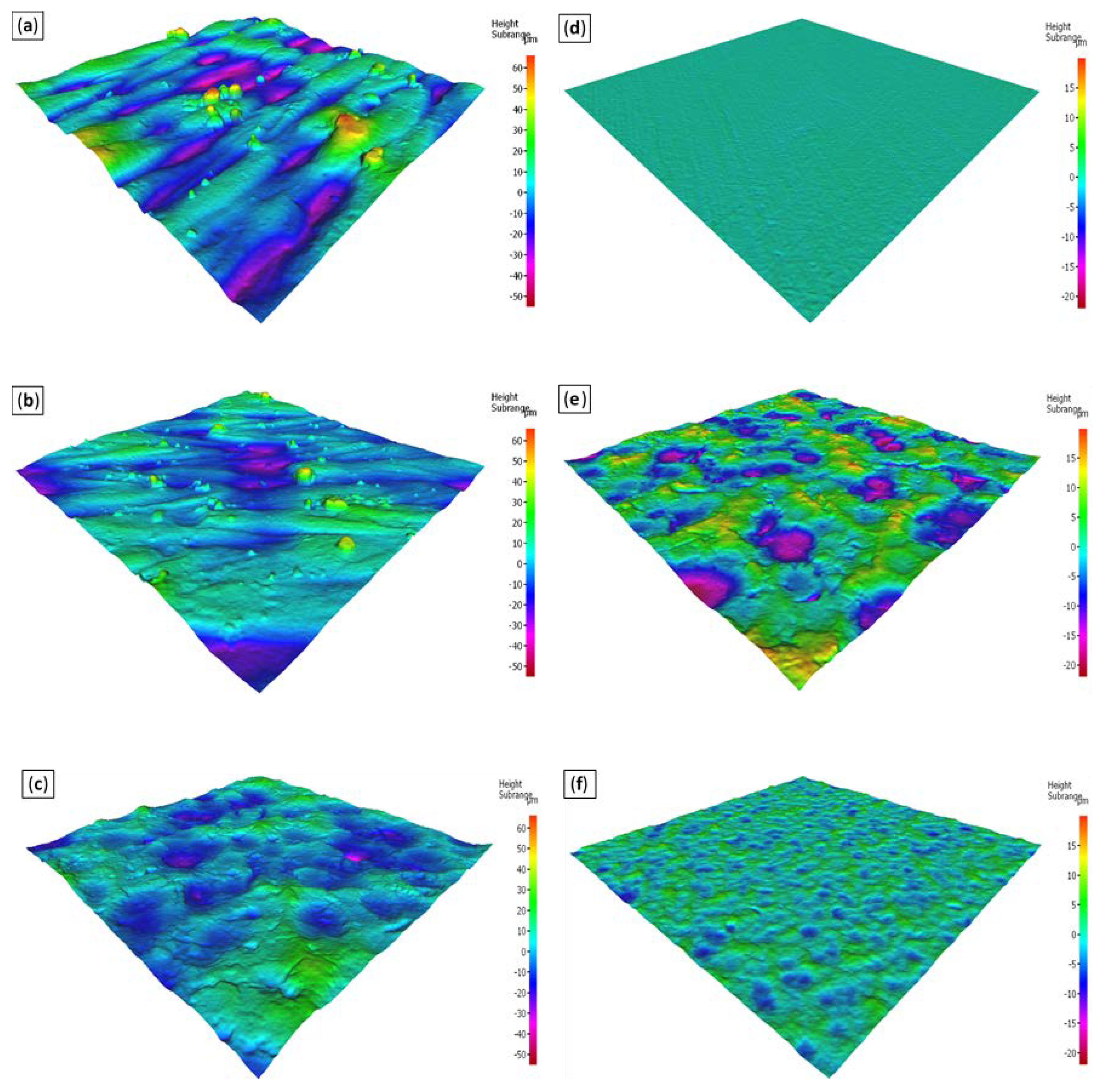
The impact of glass bead SP on the as-built AlSi10Mg surface morphology is shown in Figure 4. This figure illustrates that the defects on the as-built surface are obviously eliminated for the AB + SP, M + HSP, and M + LSP surfaces. Figure 4a,d shows the surface morphology of an AB + SP part which is similar to that obtained in the M + HSP sample, shown in Figure 4b,e, due to the use of the same shot size. For the M + HSP sample, the dimple size of shots on the surface illustrated in Figure 4b is larger than that obtained on the M + LSP surface, as shown in Figure 4c. The low-intensity SP (20.3 N) results in a more homogeneous and smooth surface due to the use of a smaller glass bead size and lower pressure. Figure 4e indicates an initiation of microcracks on the machined surface after SP that does not appear on either the AB + SP surface shown in Figure 4d or the M + LSP surface shown in Figure 4f. The initiation of these cracks refers to the higher stress concentration on the machined flat surface as compared to its effect on the as-built surface, and thus results from the stress distribution on the as-built rough surface that heals the surface defects. The observation of these cracks is in agreement with the similar observation of surface crack initiation due to high SP intensities reported by Unal et al. [24]. The trend of surface roughness change after SP shows a significant dependence on the original status of the surface topography, which is in agreement with a similar trend reported by Bagherifard et al. [14]. It is worthwhile to note that a similar surface texture is obtained after the SP of both strip and up-skin as-built samples. The average values of surface roughness and waviness of as-built, machined, and SP samples are listed in Table 3. The results showed a significant improvement in surface roughness after SP of the as-built samples, which changed from 12 µm to an average of 5.85 µm. The roughness decrease after SP could be related to the surface peak’s displacement due to the intensity applied from the shots. The low-intensity SP resulted in a smoother surface, which reached 2 µm, as compared to that obtained by the high-intensity SP (5 µm). This is related to the use of smaller sized glass beads, in addition to applying the lower intensity. According to Table 3, the results show an adverse effect on the surface waviness of the AB + SP (strip) sample. However, a slight improvement was observed on the waviness of the AB + SP (up-skin) surface. It was observed that applying high-intensity SP results in a higher surface waviness as compared to the value obtained after conducting low-intensity SP. Figure 5a,b shows the rough three-dimensional (3D) surface texture derived from the AB (strip) and AB (up-skin) samples. According to Figure 5c, a significant improvement in surface roughness can be observed after the SP of both as-built surfaces. Figure 5d illustrates the machined surface texture with very low surface roughness before SP. As shown in Figure 5e, the rougher surface is obtained by applying a higher-intensity SP than that obtained after using the low-intensity SP, as presented in Figure 5f. The increase of surface roughness after SP could negatively affect the fatigue and tensile strength [24]. Consequently, there should be an optimization of SP parameters to satisfy the design requirements of the product. It is worthwhile to note that the measured values of surface roughness in Table 3 validate the surface texture observations in Figure 5.
The surface topography of the AB (strip) + SP sample showed a significant improvement in surface roughness and was accompanied by higher surface waviness with no observation of microcrack initiation. Moreover, the low-intensity SP improved the surface roughness after SP with almost no change in the surface waviness factor.
3.2. Microstructure Characterization
The as-built AlSi10Mg microstructure is illustrated in Figure 6 along both the building direction (Z-direction) and the direction parallel to the deposited layers (XY plane). As shown in Figure 6a, an irregular geometry of melt pool shape appears along the XY plane, which is intersected with that obtained from the previous layer at 67° (the orientation angle between the layers deposited). Figure 6b shows a semi-elliptical melt pool shape along the Z-direction, which is attributed to the Gaussian effect of the incident laser beam. The microstructure of the as-built AlSi10Mg part consists of Al matrix grains surrounded by a Si network, which is related to the particle accumulated structure (PAS) formation mechanism, as reported by Prashanth et al. [25]. Figure 6c,d illustrates the microstructure inhomogeneity along both the Z-direction and the XY plane; coarser grains are observed along the melt pool border inside both directions. Figure 6e,f also shows the equiaxed grains along the XY plane, while elongated columnar grains are noticed along the Z-direction. The microstructure inhomogeneity obtained could lead to anisotropic characteristics of the as-built material [6].
After applying SP, cross-sectioned samples were polished, then etched to study the microstructure change along the Z-direction. Figure 7a shows the microstructure of the as-built sample, which represents the melt pool shape of the sample surface layer within a depth of 148 µm. It was observed that a significant deformation of the melt pool shape occurred after SP, and thus increased the depth of the melt pool shape to 189 µm, as shown in Figure 7b. The change of the melt pool shape refers to the severe plastic deformation that was applied to the sample surface. Figure 7c shows that the affected depth after the high-intensity SP of the machined surface reached 150 µm. That depth decreased to 113 µm after applying low-intensity SP on the same sample, as shown in Figure 7d. It was observed that the value of the affected depth after SP was increased, along with the Almen intensity, due to the higher amount of stress concentration applied to the surface. This is in good agreement with the trend reported by Unal et al. [24]. The observations in Figure 7a,b show that the original surface texture before SP affects the depth of the layers deformed. Figure 7e,f illustrates a significant microstructure refinement under the shot-peened surface due to the transformation of the elongated columnar grains of the as-built structure into nanoscale equiaxed grains. The microstructure refinement resulted from the plastic deformation generated and the increased density of the dislocations [14]. The high-intensity SP of the machined surface resulted in a more refined structure, in addition to considerable surface damage, as indicated in Figure 7e. However, the low-intensity SP resulted in more coarse grains and a smoother surface, as illustrated in Figure 7f.
The impact of SP on the microstructure of as-built AlSi10Mg samples was investigated under different SP intensities and sample surface textures. The SEM observations showed a significant transformation of the as-built microstructure, as illustrated in Figure 8. For the AB + SP sample, the deformed layers near to the surface due to the plastic deformation are shown in Figure 8a. The fibrous Si network surrounding the Al matrix grains in the as-built microstructure was decomposed, followed by a dynamic precipitation of spheriodized Si particles, as illustrated in Figure 8b,c. The nanoscale Si particles were precipitated within a size range of 100–500 nm, and they were homogeneously dispersed in the area affected after SP, as shown in Figure 8c. The formation of spheriodized Si particles after SP is in good agreement with the mechanism obtained after the shot-peened Al-Si cast alloys reported by Cho et al. [26]. Figure 8d–f shows the microstructure of the machined surface using high-intensity SP (M + HSP). Figure 8d illustrates that the area near the surface was affected by circular stress waves which start from the shot contract position with the surface and extended to a depth of 10 µm. Microcracks were also noticed along the layers under the sample surface, as indicated in Figure 8e. These microcracks vanished at depths more than 10 µm from the sample surface. It is worthwhile to note that the microcracks did not appear inside the AB + SP sample microstructure, which indicated that the original surface texture of the sample affects the initiation of these cracks after SP. It was also noticed that the microstructure homogeneity of the nano-recrystallized grains was improved at depths of more than 10 µm due to the disappearance of the stress waves pattern, and by using a high surface covering factor value (200%). The SEM images indicated that the area affected inside the M + HSP sample was extended to a depth of 130–150 µm before reaching the as-built microstructure, as illustrated in Figure 8f. Figure 8g illustrates the microstructure of the M + LSP sample; no stress wave patterns were observed, due to the application of low-intensity SP that reduced the plastic deformation strength. The SEM images also indicated that the depth of the M + LSP sample was around 110–120 µm, which is smaller than that obtained from the M + HSP sample. Figure 8h,i shows an incomplete dynamic precipitation of Si particles due to the low-intensity SP applied. The Si particles were precipitated in a larger size than that obtained from the M + LSP sample. The results showed agreement with the SP mechanism of the grain refinement and the hardening of the Al-Si cast alloys reported by Cho et al. [26].
The XRD phase patterns in Figure 9 show that no phase change occurred after SP. The diffraction peak identification of Al, Si, and Mg2Si were detected using the Joint Committee on Powder Diffraction Standards (JCPDS) patterns of 01-089-2837, 01-089-5012, and 00-001-1192, respectively. A significant difference was noticed in the broadening of Al and Si peaks between the AlSi10Mg as-built, machined, and SP samples, as shown in Figure 9. The magnified view in Figure 9 shows the peak broadening difference at the Al(111) peak. The peak broadening comparison of samples should indicate the crystal size change, as they have an inverse relationship according to Scherrer’s equation [27]. It is worthwhile to note that the FWHM increase after applying SP is related to a rise in the microstrain and crystal size reduction [28]. According to the values listed in Table 4, FWHM analysis shows an increase in peak broadening after SP of the as-built sample, and thus validates the refinement which occurred for both Al and Si grains. Although the as-built microstructure has a fine grain structure, as compared to the cast material of the same alloy [6], SP satisfied the additional refinement into the nanoscale grains of Al and Si. The values presented in Table 4 also show similar FWHM values of the Al(200) peak from AB + SP, M + HSP, and M + LHP samples. However, a greater refinement of the Si crystals is observed for the AB + SP and M + HSP samples than that achieved in the M + LSP sample. Consequently, the SP intensity is considered to be a significant parameter that affects the Si precipitates’ size after the SP of the as-built samples. The FWHM analysis validates the SEM observations illustrated in Figure 8. It is worthwhile to note that both the SP intensity and the surface coverage factor should be optimized to avoid surface damage as well as to satisfy the stabilization of the microstructure refinement limit [14,15,26].
3.3. Microhardness and Residual Stresses
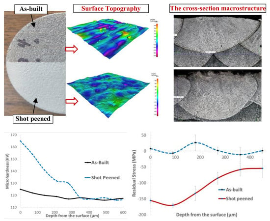
The microhardness measurements were performed on each sample surface, in addition to investigating the microhardness profile along the cross-section of as-built, machined, and SP samples. The values listed in Table 5 illustrate a 25% increase in the microhardness of the AB + SP surface that reaches 154 HV, as compared to the value resulting from the as-built and machined surfaces. The surface hardening obtained is related to the microstructure refinement, as well as the severe deformation applied due to the kinetic energy transmitted to the SP surface. A slight increase to 128 HV was observed after surface machining, resulting from the cutting process effect which modifies the microstructure of the underlying surface layers [14]. This hardness increase after surface machining is in agreement with the peak broadening observation in the XRD phase pattern of the machined sample presented in Figure 9. It was also observed that the microhardness values obtained from the M + HSP and M + LSP samples are similar, and have a 14% hardness increase as compared to the value measured after machining. The hardness values of the M + HSP and M + LSP samples indicated that the SP intensity does not have a significant impact on the surface hardening. The difference in the hardness increase percentage between the as-built and machined surfaces after SP showed that the original surface texture significantly affects the SP surface hardening. The in-depth microhardness profile of the studied samples under different SP conditions is illustrated in Figure 10. The results showed a significant increase in hardness due to the work hardening effect applied during SP. That increase started from the layers under the surface (165 HV) and gradually decreased towards the inside of the sample until reaching a stabilized value of 119 HV at a depth of 350 µm. The trend of the hardness evolution obtained after SP is related to the strain and strain rate applied to the sample surface, which is in good agreement with the results reported by Bagherifard et al. [28].
Figure 11 shows the average residual stresses that were measured on the as-built and machined surfaces before and after SP using XRD. The as-built sample showed low values of residual stresses (7.7 ± 5 MPa) due to preheating the build platform to 200 °C before starting the SLM process, and thus reducing the thermal gradient between the build layers [6]. High compressive residual stresses reached −152.5 ± 7 MPa on the SP surfaces, as compared to the values obtained for the as-built surface. The compressive residual stress increase is related to the severe stress concentration applied to the sample surface using the glass beads. A slight difference in residual stresses was observed due to the utilization of different Almen intensities, as shown in Figure 11. However, similar residual stresses were detected from the AB + SP and M + HSP samples, which proved that the surface textures used do not have a considerable effect on residual stress development. The compressive residual stresses generated could reduce the propagation and initiation of surface cracks, and result the improvement of the material fatigue strength [15].
The in-depth residual stress profile displayed in Figure 12 shows a comparison between the stress behavior of both as-built and shot-peened samples. A significant increase in compressive residual stresses was observed, as compared to values obtained from the as-built sample. For the AB + SP sample, an initial compressive stress of −155 ± 7 MPa was detected beneath the surface, which started to increase and reached a maximum value of −170 ± 7 MPa at a depth of 90 µm. This was followed by a gradual decrease until reaching a similar residual stress, as detected in the as-built sample at a depth of 450–500 µm. The results obtained from the residual stresses analysis are in good agreement with the results trend reported by Bagherifard et al. [28].
4. Summary and Conclusions
SP was applied to as-built and machined surfaces of additively manufactured AlSi10Mg samples fabricated using the SLM process. The influence of SP on the surface topography, microstructure characteristics, hardness, and residual stresses of the AlSi10Mg samples was investigated. Several conclusions are presented:
- SP is an effective tool to eliminate the surface defects generated on the surface of AlSi10Mg as-built parts. However, the waviness error of the SP surface showed relatively higher values than those obtained from the as-built surfaces. In general, the quality of the SP surface might not be achieved by optimizing the SLM process parameters to the limitations of the current machines.
- The surface roughness improvement showed similar values after the SP of the as-built and machined surfaces using a 22.9 A intensity and Gp165 glass beads (high-intensity SP). However, microcracks were detected on the shot-peened machined surface, which could affect its mechanical properties.
- The use of the 20.3 N Almen intensity and Gp50 (low-intensity SP) resulted in a better surface finish and the elimination of microcrack formation in the machined SP surface. However, the effective depth using the high-intensity SP was deeper for both the as-built and machined surfaces.
- A significant microstructure refinement was observed after SP due to the high-pressure waves applied to the sample surface. These pressure waves resulted in the breaking up of the fibrous Si network of the as-built structure, followed by the dynamic precipitation of nanoscale Si particles.
- After SP, a considerable surface hardening was measured on the top surface of both the as-built and machined samples. The as-built shot-peened surface showed the highest microhardness value of 154 HV. The microhardness in-depth profile indicated a gradually decreased hardness until it reached the as-built values of 119 HV at a 350-µm depth from the surface.
- Relatively high compressive residual stresses were detected on the shot-peened surfaces. The in-depth profile of residual stresses showed the maximum value of compressive stress to be −170 ± 7 MPa at a 90-µm depth. Then, the compressive stresses gradually decreased and reached the average values obtained from the as-built parts at 450–500 µm.
- In general, the SP of the as-built AlSi10Mg surfaces resulted in the elimination of the surface defects, microstructure refinement, surface hardening, and the application of high compressive stress into a specific depth from the sample surface. This could lead to an improvement of the mechanical properties and fatigue strength of the sample surface, and thus might satisfy the requirements of some critical parts in the industrial field.
Author Contributions
A.M. designed the experiments and performed the results analysis; M.E. and S.V. supervised the experimental work and data analysis; A.M. wrote the manuscript, M.E. and S.V. reviewed and approved the manuscript.
Acknowledgments
The authors would like to thank the Curtiss-Wright Surface Technologies Company in Brampton, Canada for the use of their shot peening facility.
Conflicts of Interest
The authors declare no conflict of interest.
References
- Fulcher, B.A.; Leigh, D.K.; Watt, T.J. Comparison of AlSi10Mg and Al 6061 Processed Through DMLS. In Proceedings of the 25th Solid Free Fabrication Symposium, Austin, TX, USA, 4–6 August 2014; pp. 404–419. [Google Scholar]
- Gibson, I.; Rosen, D.; Stucker, B. Additive Manufacturing Technologies; Springer: Berlin, Germany, 2015; ISBN 978-1-4939-2112-6. [Google Scholar]
- Srivatsan, T.S.; Sudarshan, T.S. Additive Manufacturing: Innovations, Advances, and Applications; CRC Press: Boca Raton, FL, USA, 2015; ISBN 9781498714778. [Google Scholar]
- Calignano, F.; Manfredi, D.; Ambrosio, E.P.; Iuliano, L.; Fino, P. Influence of process parameters on surface roughness of aluminum parts produced by DMLS. Int. J. Adv. Manuf. Technol. 2013, 67, 2743–2751. [Google Scholar] [CrossRef]
- Townsend, A.; Senin, N.; Blunt, L.; Leach, R.K.; Taylor, J.S. Surface texture metrology for metal additive manufacturing: A review. Precis. Eng. 2016, 46, 34–47. [Google Scholar] [CrossRef]
- Maamoun, A.H.; Elbestawi, M.; Dosbaeva, G.K.; Veldhuis, S.C. Thermal Post-processing of AlSi10Mg parts produced by Selective Laser Melting using recycled powder. Addit. Manuf. 2018, 21, 234–247. [Google Scholar] [CrossRef]
- Bagherifard, S.; Fernandez-Pariente, I.; Ghelichi, R.; Guagliano, M. Fatigue behavior of notched steel specimens with nanocrystallized surface obtained by severe shot peening. Mater. Des. 2013, 45, 497–503. [Google Scholar] [CrossRef]
- Oguri, K. Fatigue life enhancement of aluminum alloy for aircraft by Fine Particle Shot Peening (FPSP). J. Mater. Process. Technol. 2011, 211, 1395–1399. [Google Scholar] [CrossRef]
- Curtis, S.; De Los Rios, E.R.; Rodopoulos, C.A.; Levers, A. Analysis of the effects of controlled shot peening on fatigue damage of high strength aluminium alloys. Int. J. Fatigue 2003, 25, 59–66. [Google Scholar] [CrossRef]
- Hetram, L.S.; Om, H.; Hetram, L.S.; Om, H. Shot Peening Effects on Material Properties: A Review. Int. J. Innov. Res. Sci. Technol. 2015, 1, 480–484. [Google Scholar]
- Zupanc, U.; Grum, J. Surface integrity of shot peened aluminium alloy 7075-T651. Stroj. Vestn. J. Mech. Eng. 2011, 57, 379–384. [Google Scholar] [CrossRef]
- Mehmood, A.; Hammouda, M.M.I. Effect of shot peening on the fatigue life of 2024 Aluminum alloy. Fail. Eng. Mater. Struct. 2007, 2, 3363–3370. [Google Scholar]
- Chen, G.; Yan, J.; Tian, T.; Zhang, X.; Li, Z.; Zhou, W. Effect of wet shot peening on Ti-6Al-4V alloy treated by ceramic beads. Trans. Nonferr. Met. Soc. China 2014, 24, 690–696. [Google Scholar] [CrossRef]
- Bagherifard, S.; Slawik, S.; Fernández-Pariente, I.; Pauly, C.; Mücklich, F.; Guagliano, M. Nanoscale surface modification of AISI 316L stainless steel by severe shot peening. Mater. Des. 2016, 102, 68–77. [Google Scholar] [CrossRef]
- Bagherifard, S.; Ghelichi, R.; Guagliano, M. On the shot peening surface coverage and its assessment by means of finite element simulation: A critical review and some original developments. Appl. Surf. Sci. 2012, 259, 186–194. [Google Scholar] [CrossRef]
- Qandil, A.; Zaid, A.I.O. Effect of shot peening and grain refinement on the fatigue life and strength of commercially pure Al and two of its alloys: Al-2024-T3 and Al-7075-T6. In IOP Conference Series: Materials Science and Engineering; IOP Publishing: Bristol, UK, 2016; Volume 146, p. 12028. [Google Scholar]
- AlMangour, B.; Yang, J.M. Improving the surface quality and mechanical properties by shot-peening of 17-4 stainless steel fabricated by additive manufacturing. Mater. Des. 2016, 110, 914–924. [Google Scholar] [CrossRef]
- Damon, J.; Dietrich, S.; Vollert, F.; Gibmeier, J.; Schulze, V. Process dependent porosity and the influence of shot peening on porosity morphology regarding selective laser melted AlSi10Mg parts. Addit. Manuf. 2018, 20, 77–89. [Google Scholar] [CrossRef]
- Uzan, N.E.; Ramati, S.; Shneck, R.; Frage, N.; Yeheskel, O. On the effect of shot-peening on fatigue resistance of AlSi10Mg specimens fabricated by additive manufacturing using selective laser melting (AM-SLM). Addit. Manuf. 2018, 21, 458–464. [Google Scholar] [CrossRef]
- Active Standard ASTM F3049. Standard Guide for Characterizing Properties of Metal Powders Used for Additive Manufacturing Processes; ASTM International: West Conshohocken, PA, USA, 2014; pp. 1–3. [Google Scholar] [CrossRef]
- Tolochko, N.K.; Mozzharov, S.E.; Yadroitsev, I.A.; Laoui, T.; Froyen, L.; Titov, V.I.; Ignatiev, M.B. Balling processes during selective laser treatment of powders. Rapid Prototyp. J. 2004, 10, 78–87. [Google Scholar] [CrossRef]
- Aboulkhair, N.T.; Maskery, I.; Tuck, C.; Ashcroft, I.; Everitt, N.M. On the formation of AlSi10Mg single tracks and layers in selective laser melting: Microstructure and nano-mechanical properties. J. Mater. Process. Technol. 2016, 230, 88–98. [Google Scholar] [CrossRef] [Green Version]
- Yadroitsev, I.; Krakhmalev, P.; Yadroitsava, I.; Johansson, S.; Smurov, I. Energy input effect on morphology and microstructure of selective laser melting single track from metallic powder. J. Mater. Process. Technol. 2013, 213, 606–613. [Google Scholar] [CrossRef]
- Unal, O.; Varol, R. Almen intensity effect on microstructure and mechanical properties of low carbon steel subjected to severe shot peening. Appl. Surf. Sci. 2014, 290, 40–47. [Google Scholar] [CrossRef]
- Prashanth, K.G.; Eckert, J. Formation of metastable cellular microstructures in selective laser melted alloys. J. Alloys Compd. 2017, 707, 27–34. [Google Scholar] [CrossRef]
- Cho, K.T.; Yoo, S.; Lim, K.M.; Kim, H.S.; Lee, W.B. Effect of Si content on surface hardening of Al-Si alloy by shot peening treatment. J. Alloys Compd. 2011, 509, S265–S270. [Google Scholar] [CrossRef]
- Langford, J.I.; Wilson, A.J.C. Scherrer after sixty years: A survey and some new results in the determination of crystallite size. J. Appl. Crystallogr. 1978, 11, 102–113. [Google Scholar] [CrossRef] [Green Version]
- Bagherifard, S.; Beretta, N.; Monti, S.; Riccio, M.; Bandini, M.; Guagliano, M. On the fatigue strength enhancement of additive manufactured AlSi10Mg parts by mechanical and thermal post-processing. Mater. Des. 2018, 145, 28–41. [Google Scholar] [CrossRef]
Figure 1.
(a) Particle size distribution (PSD) of the AlSi10Mg powder; (b) SEM observations of the powder morphology.
Figure 1.
(a) Particle size distribution (PSD) of the AlSi10Mg powder; (b) SEM observations of the powder morphology.

Figure 2.
Various surface textures of the AlSi10Mg samples of as-built, rough machined, and shot-peened areas.
Figure 2.
Various surface textures of the AlSi10Mg samples of as-built, rough machined, and shot-peened areas.

Figure 3.
(a) SEM observations of the as-built AlSi10Mg surface defects, (b) partially melted powder particle, (c) ellipsoidal balling, (d) track of the strip laser scan, and (e) pore formed on the surface.
Figure 3.
(a) SEM observations of the as-built AlSi10Mg surface defects, (b) partially melted powder particle, (c) ellipsoidal balling, (d) track of the strip laser scan, and (e) pore formed on the surface.

Figure 4.
The impact of shot peening on the surface morphology of the AlSi10Mg sample: (a,d) as-built (AB) + shot-peened (SP), (b,e) machined (M) + high-intensity SP (HSP), (c,f) M + low-intensity SP (LSP).
Figure 4.
The impact of shot peening on the surface morphology of the AlSi10Mg sample: (a,d) as-built (AB) + shot-peened (SP), (b,e) machined (M) + high-intensity SP (HSP), (c,f) M + low-intensity SP (LSP).

Figure 5.
Three-dimensional (3D) surface texture of the AlSi10Mg samples: (a) AB (strip scan); (b) AB (up-skin); (c) AB + SP; (d) M; (e) M + HSP; and (f) M + LSP.
Figure 5.
Three-dimensional (3D) surface texture of the AlSi10Mg samples: (a) AB (strip scan); (b) AB (up-skin); (c) AB + SP; (d) M; (e) M + HSP; and (f) M + LSP.

Figure 6.
Microstructure observation s of the as-built AlSi10Mg sample: along the XY plane; (a) melt pool shape; (b) melt pool grain structure; (c) equiaxed grain along the Z-direction; (d) melt pool shape; (e) melt pool grain structure; (f) elongated grains.
Figure 6.
Microstructure observation s of the as-built AlSi10Mg sample: along the XY plane; (a) melt pool shape; (b) melt pool grain structure; (c) equiaxed grain along the Z-direction; (d) melt pool shape; (e) melt pool grain structure; (f) elongated grains.

Figure 7.
The influence of shot peening on the melt pool shape of the AlSi10Mg sample, (a) AB, (b) AB + SP, (c) M + HSP (d) M + LSP, and a surface profile at high magnification; (e) M + HSP, (f) M + LSP.
Figure 7.
The influence of shot peening on the melt pool shape of the AlSi10Mg sample, (a) AB, (b) AB + SP, (c) M + HSP (d) M + LSP, and a surface profile at high magnification; (e) M + HSP, (f) M + LSP.

Figure 8.
Microstructure evolution after the shot peening of the AlSi10Mg sample under different magnifications: (a–c) AB + SP; (d–f) M + HSP; and (g–i) M + LSP.
Figure 8.
Microstructure evolution after the shot peening of the AlSi10Mg sample under different magnifications: (a–c) AB + SP; (d–f) M + HSP; and (g–i) M + LSP.

Figure 9.
The X-ray diffraction (XRD) phase pattern of the AlSi10Mg samples under different SP conditions.
Figure 9.
The X-ray diffraction (XRD) phase pattern of the AlSi10Mg samples under different SP conditions.

Figure 10.
The in-depth microhardness profile of the AlSi10Mg samples under various SP conditions.

Figure 11.
The impact of SP on the normal residual stress on the AlSi10Mg sample surface.

Figure 12.
The in-depth residual stress profile from the AlSi10Mg sample surface.


Table 1.
The energy dispersive X-ray spectroscopy (EDS) measurements for the weight% of the chemical composition elements of the AlSi10Mg powder.
Table 1.
The energy dispersive X-ray spectroscopy (EDS) measurements for the weight% of the chemical composition elements of the AlSi10Mg powder.
| Si | Mg | Fe | Cu | Sn | Pb | Zn | Al |
|---|---|---|---|---|---|---|---|
| 10.58 | 0.37 | 0.41 | 0.08 | 0.05 | 0.05 | 0.04 | Balance |
Table 2.
Processing parameters for the selective laser melting (SLM) of AlSi10Mg samples.
| SLM Parameters | Laser Power (W) | Scan Speed (mm/s) | Hatch Spacing (mm) | Layer Orientation Angle (°) | Layer Thickness (µm) | Scan Strategy |
|---|---|---|---|---|---|---|
| In-Core | 370 | 1300 | 0.19 | 67 | 30 | Stripes |
| Up-Skin | 360 | 1000 | 0.21 |
Table 3.
The effect of shot peening on both surface roughness and waviness.
| Surface | AB (Strip) | AB (Up-Skin) | AB + SP (Strip) | AB + SP (Up-Skin) | M | M + HSP | M + LSP |
|---|---|---|---|---|---|---|---|
| Average Ra (µm) | 11.96 | 6.98 | 5.92 | 5.82 | 0.22 | 5.34 | 2.05 |
| Surface Waviness (µm) | 0.38 | 2.2 | 2.79 | 1.92 | 0.06 | 0.23 | 0.07 |
Table 4.
The average full width at the half maximum (FWHM) of Al and Si peaks of the as-built, rough-machined, and SP samples.
Table 4.
The average full width at the half maximum (FWHM) of Al and Si peaks of the as-built, rough-machined, and SP samples.
| Sample | AB | AB + SP | M | M + HSP | M + LSP |
|---|---|---|---|---|---|
| Al (200) FWHM (deg.) | 0.246 | 0.332 | 0.276 | 0.321 | 0.317 |
| Si (220) FWHM (deg.) | 0.981 | 1.454 | 1.104 | 1.141 | 1.129 |
Table 5.
Surface microhardness of the AlSi10Mg samples under various conditions.
| Surface | AB | AB + SP | M | M + HSP | M + LSP |
|---|---|---|---|---|---|
| Microhardness (HV) | 120 | 154 | 128 | 147 | 145 |
© 2018 by the authors. Licensee MDPI, Basel, Switzerland. This article is an open access article distributed under the terms and conditions of the Creative Commons Attribution (CC BY) license (http://creativecommons.org/licenses/by/4.0/).
Share and Cite
MDPI and ACS Style
Maamoun, A.H.; Elbestawi, M.A.; Veldhuis, S.C. Influence of Shot Peening on AlSi10Mg Parts Fabricated by Additive Manufacturing. J. Manuf. Mater. Process. 2018, 2, 40. https://doi.org/10.3390/jmmp2030040
AMA Style
Maamoun AH, Elbestawi MA, Veldhuis SC. Influence of Shot Peening on AlSi10Mg Parts Fabricated by Additive Manufacturing. Journal of Manufacturing and Materials Processing. 2018; 2(3):40. https://doi.org/10.3390/jmmp2030040
Chicago/Turabian StyleMaamoun, Ahmed H., Mohamed A. Elbestawi, and Stephen C. Veldhuis. 2018. "Influence of Shot Peening on AlSi10Mg Parts Fabricated by Additive Manufacturing" Journal of Manufacturing and Materials Processing 2, no. 3: 40. https://doi.org/10.3390/jmmp2030040