A Compact Transmitter Array to Reproduce the Acoustic Signature of Neutrino in Water †
by
 , ,
, ,
Miguel Ardid
1,2 ,
,
Manuel Bou-Cabo
3,
Dídac D. Tortosa
1,2,*,
Carlos D. Llorens-Álvarez
1,2 and
Juan A. Martínez-Mora
1,2 
1
Universitat Politècnica de València (UPV), Paranimf 1,46730 Grau de Gandia, València, Spain
2
Institut d’Investigació per a la Gestió Integrada de les Zones Costaneres (IGIC), Paranimf 1,46730 Grau de Gandia, València, Spain
3
Instituto Español de Oceanografía (IEO), Mixed unit UPV-IEO, Paranimf 1,46730 Grau de Gandia, València, Spain
*
Author to whom correspondence should be addressed.
†
Presented at the 5th International Electronic Conference on Sensors and Applications, 15–30 November 2018; Available online: https://ecsa-5.sciforum.net.
Proceedings 2019, 4(1), 4; https://doi.org/10.3390/ecsa-5-05748
Published: 14 November 2018
(This article belongs to the Proceedings of 5th International Electronic Conference on Sensors and Applications)
Abstract
:In this work, we present a prototype of a compact linear array with three elements that is able to reproduce the acoustic signature of Ultra High Energy (UHE) neutrino interaction in water using the parametric acoustic effect. Mimicking this signal is important because it is a very directive bipolar transient signal with cylindrical symmetry. We characterized the prototype by measuring the signal waveform, the attenuation, intensity variation and directivity, with numerical simulations and experimentally in a pool. We also studied different kinds of signals to determine the best application for the array. The results confirmed the utility of this array for the proposed application in marine neutrino telescopes.
1. Introduction
Several decades ago, the acoustic technique was proposed for the detection of ultra high energy (UHE) neutrinos [1]. When there is a UHE neutrino interaction in water, a shower of particles is produced, so its energy is released in a small cylindrical-like volume, which is a few centimeters in radius and several meters in length. This local heating, which is almost instantaneous leads to a short pressure pulse signal, with a bipolar shape in time and a very directive pattern (pancake-like), being emitted perpendicularly to the shower axis. The feasibility of the technique is still under discussion and several experiments and tools have been proposed to test it [2,3,4]. This technique could be implemented in the KM3NeT telescope, which is a new optical-based deep-sea neutrino telescope that is under construction with a volume of several cubic kilometers. The fact that this facility has to integrate hundreds of acoustic sensors in the acoustic positioning system for calibration purposes, triggers the idea of using the sensors for acoustic detection of neutrinos as well.
If the KM3NeT does eventually use the acoustic sensors for neutrino detection, it is necessary that these sensors are well calibrated for this purpose. An emitter that is able to reproduce neutrino’s acoustic signature can be used for this purpose, and thus, the feasibility of the technique can be studied directly.
This paper describes the design of the emitter array based on simulations and it also presents the first experimental results to characterize the array.
2. Reproduction of Neutrino’s Acoustic Signature with Parametric Effect
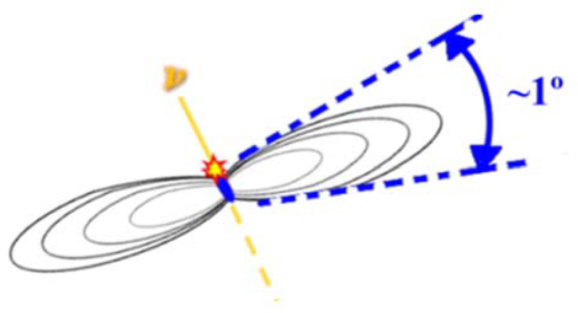
G.A. Askaryan predicted that a thermo-acoustic pulse is produced after a UHE neutrino interaction in water that develops a shower of particles almost at the speed of light with a very localized deposition of energy. The acoustic signal is very singular because it is very directive, even though it is composed by low-ultrasonic frequency, between 2 to 50 kHz (see Figure 1). Neutrino’s acoustic signature is similar to a bipolar pulse with ~1 mPa of amplitude for a 1 EeV neutrino measured at 1 km [4].
To reproduce the directive acoustic bipolar pulse, we will use the parametric effect [3]. This principle consists in emitting a beam with two close frequencies with high energy (1st beam). The propagation in the non-linear medium will produce combinations of these two frequencies (2nd beam, see Figure 2). Specifically, the difference frequency of the 1st beam is used to get low-ultrasonic frequency with a pronounced directivity [6].
The waveform of the signal produced by parametric effect can be predicted with Equation (1).
where is the resulting pressure wave along , space and , time, is the non-linear parameter of the medium, is the pressure of the 1st beam, is the area of the vibrating surface, is the density of the medium, is the velocity of the propagation, is the absorption coefficient in medium, and is the envelope of the modulation in emitted signal. So, it is proportional to the second derivative of the square of the envelope function of the emitted signal.
3. Design and Development of a Transmitter Array
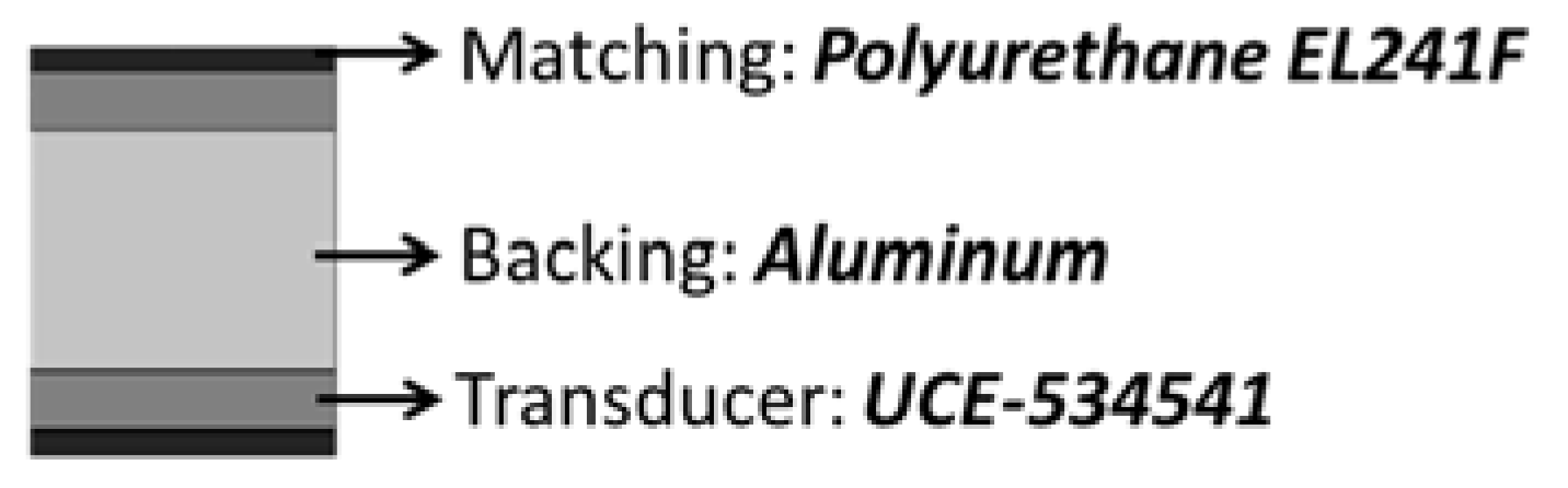
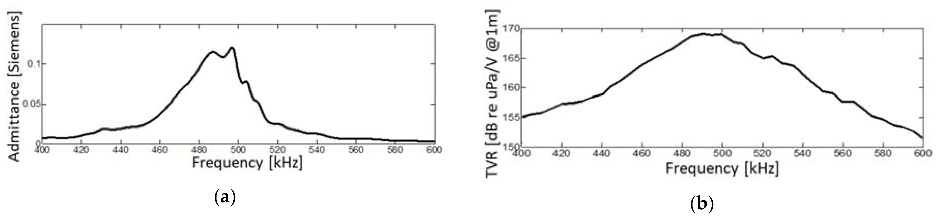
The design of the array begun with the study of a single element to select the type of transmitter [7]. The single element elected was a commercial piezo-ceramic cylindrical transducer (UCE-534541) mixed with polyurethane EL241F as matching and aluminum as backing (see Figure 3). It has a resonance frequency of around the 495 kHz (see Figure 4).
The aim of the acoustic array is to accomplish the emission of a bipolar pulse signal with similar characteristics to the acoustic signal produced by a 1020 eV neutrino interacting in water at a distance of 1 km, with a bipolar pulse with an amplitude of about 10 mPa (basically corresponding to a 2–50 kHz frequency range) and an approximate opening angle of 1°, thus, emulating the neutrino’s acoustic signal in water [1].
In the first studies of parametric emission with a bipolar pulse in a single element the opening angle of the signal at 1 km from the emission of three and five elements of the array was simulated to study the best distances between emitter elements considering the propagation of the wave (see Figure 5). The propagation was performed while taking into account the losses from the medium absorption coefficient (under the conditions of the KM3NeT telescope) and the spherical divergence.
Finally, previous studies indicate that the optimum distance between elements is 14 cm.
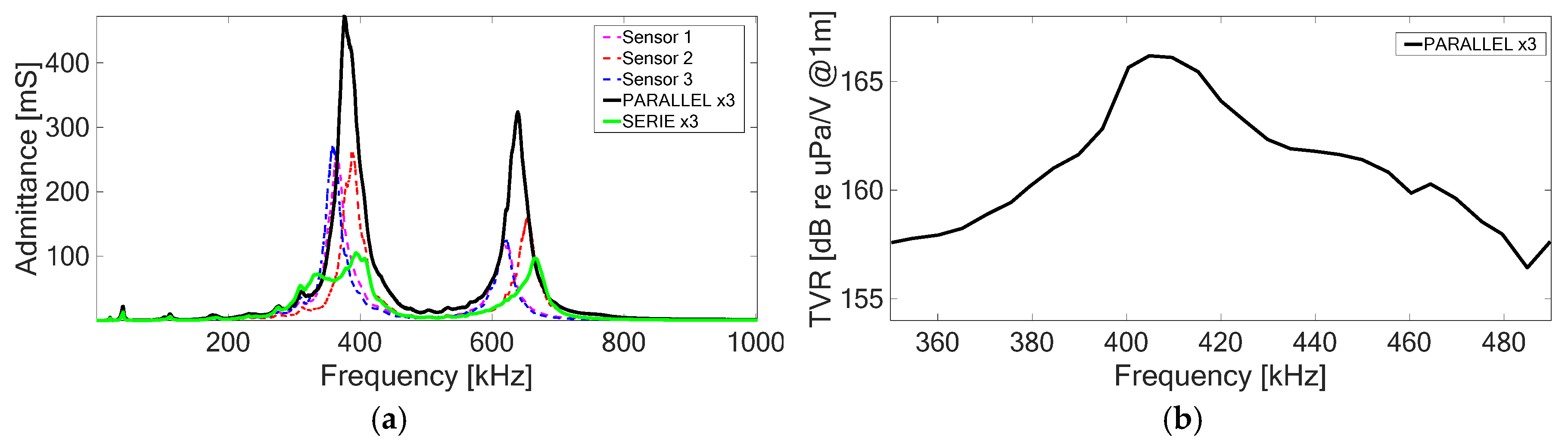
Once the distance between elements was selected, the next step was to develop an array with 5 emitter elements (see Figure 6). When the elements were installed in array, the common subjection (aluminum bar) produces displacement of the resonance frequency. Specifically, the resonance frequency in the elements assembled in the array bar appeared to be around 380 kHz (not 495 kHz) with a secondary resonance of round 640 kHz (see Figure 7).
4. Results
The experimental results in this paper show the characterization of the array with three elements connected in parallel. The characterization was performed for the first beam (linear range) and for the second beam (parametric range).
After characterizing the array in terms of admittance and transmitter voltage response (TVR) (see Figure 7), the array in parallel configuration was studied in depth. For this, the generation of the secondary parametric acoustic bipolar pulse as a function of the feeding voltage was studied, see Figure 8a). The different behavior of the primary beam (linear) can be directly compared to that of the secondary beam (parametric generation). Also, in this study a difference can be noticed in the generation and propagation of signals as a function of the distance between the emitter array and receiver sensor, as shown in Figure 8b.
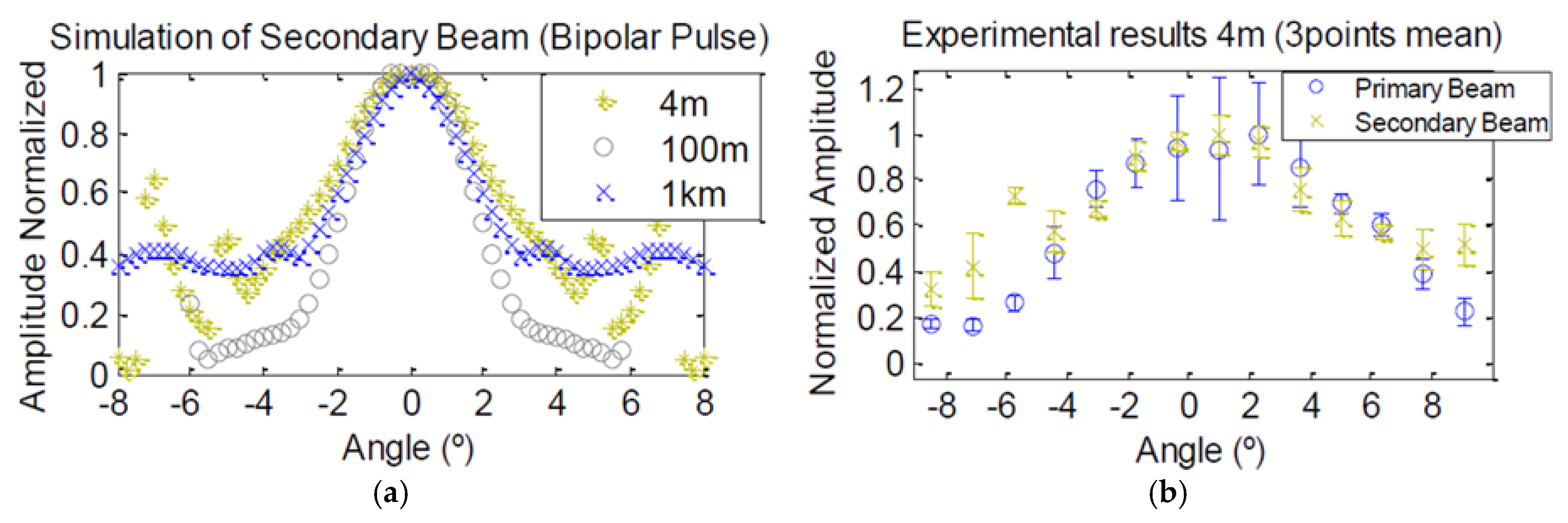
The directivity of the array with an acoustic bipolar pulse is shown in Figure 9. In Figure 9a the directivity obtained by simulations for the array, based on the experimentally measured directivity of a single element, is presented for distances of 4, 100 and 1000 m. In Figure 9b, the experimental measures for the array with a distance between array and receiver of 4 m is shown.
5. Conclusions and Future Step
Based on these first studies of the prototype array, we can conclude that the designed array is able to emit an acoustic signal that mimics the UHE neutrino acoustic signature. The prototype with three elements was characterized for parametric generation. Similar directivity was obtained for primary and secondary beams, thus achieving the goal of having a final directionality of a few degrees (FWHM in amplitude) for the bipolar pulse.
The next step in this prototype is improving the electronics in order to increase the power of the signal for use over longer distances and for in situ tests in KM3NeT.
Funding
We acknowledge the financial support of Plan Estatal de Investigación, ref. FPA2015-65150-C3-2-P (MINECO/FEDER).
Acknowledgments
We thank María Saldaña Coscollar for the discussions and collaboration on this topic during her PhD studies.
Conflicts of Interest
The authors declare no conflict of interest.
References
- Askaryan, G.A. Acoustic Hydrodynamical emission of tacks of ionising particles in stable liquids. The Soviet J. Atom. Energy 1957, 3, 921–923. [Google Scholar] [CrossRef]
- Aguilar, J.A.; Al Samarai, I.; Albert, A.; Anghinolfi, M.; Anton, G.; Anvar, S.; Ardid, M.; Jesus, A.A.; Astraatmadja, T.; Aubert, J.J.; et al. AMADEUS, The acoustic neutrino detection test system of the ANTARES deep-sea neutrino telescope. Nucl. Instrum. Methods Phys. Res. Sect. A 2011, 626, 128–143. [Google Scholar] [CrossRef]
- Ardid, M. Calibration in acoustic detection of neutrinos. Nucl. Instrum. Methods Phys. Res. Sect. A 2009, 604, 203–207. [Google Scholar] [CrossRef]
- Ardid, M.; Martínez-Mora, J.A.; Bou-Cabo, M.; Larosa, G.; Adrián-Martínez, S.; Llorens, C.D. Acoustic Transmitters for Underwater Neutrino Telescopes. Sensors 2012, 12, 4113–4132. [Google Scholar] [CrossRef] [PubMed]
- Saldaña, M. Acoustic System Development for Neutrino Underwater Detectors. Ph.D. Thesis, Universitat Politècnica de València, València, Spain, June 2017. [Google Scholar] [CrossRef]
- Moffet, M.B.; Mellen, R.H. Model for parametric acoustic sources. J. Acoust. Soc. Am. 1977, 61, 325–337. [Google Scholar] [CrossRef]
- Saldaña, M.; Llorens, C.D.; Felis, I.; Martínez-Mora, J.A.; Ardid, M. Transducer Development and Characterization for Underwater Acoustic Neutrino Detection Calibration. Sensors 2016, 16, 1210–1222. [Google Scholar] [CrossRef] [PubMed]
Figure 1.
Scheme of the development of the directive acoustic pulse by a neutrino interaction with water (or ice) [5].
Figure 1.
Scheme of the development of the directive acoustic pulse by a neutrino interaction with water (or ice) [5].

Figure 2.
Scheme of effects of parametric generation. Emitting two narrow powerful beams at different frequencies (1st beam), produces combinations of these frequencies (2nd beam) along the medium.
Figure 2.
Scheme of effects of parametric generation. Emitting two narrow powerful beams at different frequencies (1st beam), produces combinations of these frequencies (2nd beam) along the medium.

Figure 3.
Scheme of materials used in the acoustic emitter sensor of the array. The emitter is an UCE-534541 piezo-ceramic recovered with polyurethane EL241F in the outside layer as matching, and aluminum in the inside layer as backing.
Figure 3.
Scheme of materials used in the acoustic emitter sensor of the array. The emitter is an UCE-534541 piezo-ceramic recovered with polyurethane EL241F in the outside layer as matching, and aluminum in the inside layer as backing.

Figure 4.
Measures of the acoustic emitter sensor: (a) Admittance. (b) Transmitter voltage response (TVR).
Figure 4.
Measures of the acoustic emitter sensor: (a) Admittance. (b) Transmitter voltage response (TVR).

Figure 5.
Example of simulation result for 4 different opening angles of the signal in the propagation at 1 km: (a) Result for 3 elements in the array with 5 cm of distance between them. (b) Result for 5 elements in the array with 5 cm of distance between them [5].
Figure 5.
Example of simulation result for 4 different opening angles of the signal in the propagation at 1 km: (a) Result for 3 elements in the array with 5 cm of distance between them. (b) Result for 5 elements in the array with 5 cm of distance between them [5].

Figure 6.
Final design of the array: (a) Configuration of the scheme. (b) Picture of the array in the pool at the UPV laboratory in Gandia harbor.
Figure 6.
Final design of the array: (a) Configuration of the scheme. (b) Picture of the array in the pool at the UPV laboratory in Gandia harbor.

Figure 7.
Measures for acoustic emitter array (3 elements): (a) Admittance (b) Transmitter voltage response (TVR) measure in dB refers to µPa/V at 1 m distance with 3 elements in parallel.
Figure 7.
Measures for acoustic emitter array (3 elements): (a) Admittance (b) Transmitter voltage response (TVR) measure in dB refers to µPa/V at 1 m distance with 3 elements in parallel.

Figure 8.
Characterization measures in the array with three elements: (a) Variation in voltage to show the appearance of parametric effect. (b) The amplitude evolution of two beams from 1 to 4 m [5].
Figure 8.
Characterization measures in the array with three elements: (a) Variation in voltage to show the appearance of parametric effect. (b) The amplitude evolution of two beams from 1 to 4 m [5].

Figure 9.
Directivity of the array with three elements: (a) Simulation for different distances (b) Experimental measure for 4 m distance [5].
Figure 9.
Directivity of the array with three elements: (a) Simulation for different distances (b) Experimental measure for 4 m distance [5].

© 2018 by the authors. Licensee MDPI, Basel, Switzerland. This article is an open access article distributed under the terms and conditions of the Creative Commons Attribution (CC BY) license (https://creativecommons.org/licenses/by/4.0/).
Share and Cite
MDPI and ACS Style
Ardid, M.; Bou-Cabo, M.; Tortosa, D.D.; Llorens-Álvarez, C.D.; Martínez-Mora, J.A. A Compact Transmitter Array to Reproduce the Acoustic Signature of Neutrino in Water. Proceedings 2019, 4, 4. https://doi.org/10.3390/ecsa-5-05748
AMA Style
Ardid M, Bou-Cabo M, Tortosa DD, Llorens-Álvarez CD, Martínez-Mora JA. A Compact Transmitter Array to Reproduce the Acoustic Signature of Neutrino in Water. Proceedings. 2019; 4(1):4. https://doi.org/10.3390/ecsa-5-05748
Chicago/Turabian StyleArdid, Miguel, Manuel Bou-Cabo, Dídac D. Tortosa, Carlos D. Llorens-Álvarez, and Juan A. Martínez-Mora. 2019. "A Compact Transmitter Array to Reproduce the Acoustic Signature of Neutrino in Water" Proceedings 4, no. 1: 4. https://doi.org/10.3390/ecsa-5-05748