Proceeding Paper

Phase-Shifting Shearing Interference Microscope with Savart Shear Prism and Rotatable Analyzer †

1
Department of Electro-optical Engineering, National Taipei University of Technology, 1, Sec. 3, Chung-Hsiao East Road, Taipei 10608, Taiwan
2
Shuztung Machinery Industrial Co., Ltd., 30, Houke S. Rd., Houli Dist., Taichung City 42152, Taiwan
*
Author to whom correspondence should be addressed.
Presented at the 18th International Conference of experimental Mechanics (ICEM18), Brussels, Belgium, 1–5 July 2018.
Proceedings 2018, 2(8), 556; https://doi.org/10.3390/ICEM18-05483
Published: 28 August 2018
(This article belongs to the Proceedings of The 18th International Conference on Experimental Mechanics)

Abstract

:
A phase-shifting shearing interference microscope (PSSIM) is introduced in this paper. It is constructed by placing a Savart shear prism between the objective and sample of a polarizing microscope with a rotatable analyzer as the phase-shifter, and it is capable of determining contour height variation and deformation strain using the principle of shearing interferometry. This paper not only interprets the measurement theory but also presents an experimental setup of the PSSIM. Moreover, this paper exhibits the results from the uses of the setup; the results demonstrate the validity and applicability of the PSSIM.

1. Introduction

Shearing interferometer carry out their measurements by the interference of a wavefront from the test sample with a shifted one of the same wavefront, they are therefore highly resistant to environmental perturbations and widely adopted when in-situ measurements are necessary. According to the measurement theories, shearing interferometers for micro-component examinations can be divided into microscopic ESPIs (electronic speckle pattern interferometers) [1,2,3,4,5,6,7] and microscopic SIs (shearing interferometers) [8,9,10,11,12,13]. When using microscopic ESPIs, the object must be with an optically rough surface and the interference pattern is full of random speckle. Microscopic ESPIs are hence, in general, not for estimating the quality but for investigating the strains of the surface, and they achieve the investigations by two techniques: speckle pattern subtraction and phase-shifting.
In contrast to microscopic ESPIs, microscopic SIs are favorable when the object is with a mirror-like surface and they get an interference pattern with phase directly proportional to the slope (or contour height variation) of the object. Microscopic SIs are therefore applicable for both surface quality estimations and strain determinations. However, for eliminating the error due to the aberration of the wavefront through the objective, some of them [8,10,11,12] utilize a collimator to appropriately collimate the light wave from the source and replace the objective with an afocal microscopic system to collimate the light wave incident on the sample, this narrows the effective numerical aperture of the objective and accordingly decreases the resolving power of the measurements; some of them [9,13] use a filter to erase the extra phase due to the aberration, this may lead to reconstruction distortion if the window of the filter is not correctly laid down.

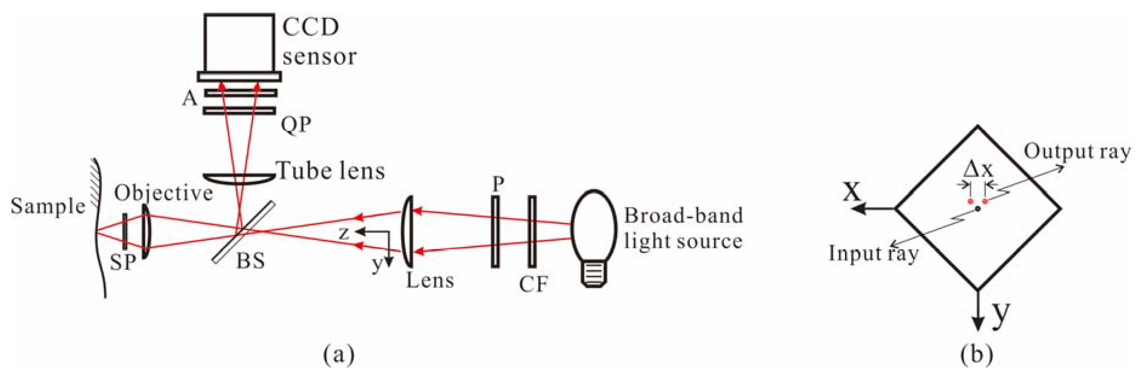
2. Configuration and Theory

A novel phase-shifting shearing interference microscope (PSSIM) is therefore proposed. As that shown in Figure 1, the PSSIM is identical to a conventional phase-shifting polarizing microscope except for having a Savart prism placed between the objective and sample, where the polarizer converts the beam from the source into a linearly polarized beam; the lens and objective sequentially collect the incoming beam to illuminate the sample with contour height of W(x,y); the Savart prism shears the beam from the objective into two beams with a shear distance Δx and then recombines the sheared beams as they return from the sample; and the objective maps the sample image carried by the recombined beam onto the charge-coupled device (CCD) sensor. Apparently, this image is a shearing interference pattern, a derivation and a numerical calculation regarding this pattern have been done, the results prove that the intensity of the interference pattern has a form of
I = I a v [ 1 + γ cos ( 1 C 4 π λ Δ W ( x , y ) + 2 α ) ] = I a v [ 1 + γ cos ( Δ φ x + 2 α ) ] ,
where λ and ΔW(x,y) represent central wavelength of the light source and contour height variation, respectively, γ and C are fringe contrast and period correction factor, respectively, and
Δ φ x = 1 C 4 π λ Δ W ( x , y ) ,
or, if the sample surface is smooth,
Δ φ x = 1 C 4 π λ W ( x , y ) x Δ x .
Equations (1)–(3) indicate that the proposed PSSIM is capable of examining contour height variation, or determining deformation strain using
W ( x , y ) x | d = W ( x , y ) x | a f t e r W ( x , y ) x | b e f o r e
where W ( x , y ) / x | b e f o r e and W ( x , y ) / x | a f t e r represent the slopes of the sample before and after the sample is deformed, respectively. Note that ΔW(x,y), W ( x , y ) / x | b e f o r e and W ( x , y ) / x | a f t e r are extracted using a phase- shifting algorithm, where the phase-shifting images for the phase-shifting algorithm are the images with different phase shifts, i.e., 2α. Also note that the contour height variation and strain along y-direction can be obtained by rotating the Savart prism about z-axis by 90° and a process the same as that for x-direction shearing. The strain along y-direction is symbolized as W ( x , y ) / y | d .

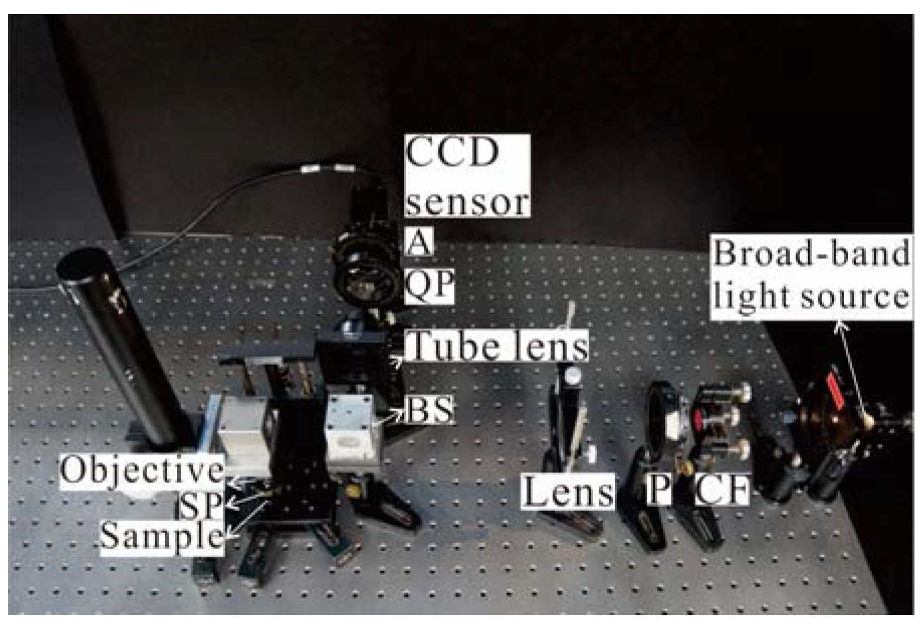
3. Experimental Setup and Results

To implement the measurement concept introduced in this paper, a setup comprising the proposed PSSIM and an image processing system was constructed. In the PSSIM, a photo of which is shown in Figure 2, the light source was a halogen lamp; the color filter exported a red-light beam with λ = 0.635 μm; the Savart prism, made of quartz, sheared the input beam by a distance of Δx = 20.75 μm; the objective was M Plan Apo 2X from Mitutoyo Corporation (Kawasaki, Japan) or CFI TU Plan Epi ELWD 20X from Nikon Corporation (Tokyo, Japan); and the quarter-wave plate was of broadband type obtained from Photoelastic Division of Measurements Group Inc. (Wendell, NC, USA).
The image processing system comprised a personal computer and three programs executed by the computer: image grabbing, evaluation, and display. The image grabbing involved acquiring the phase-shifted images on the CCD sensor and storing them in the memory of the computer; the evaluation retrieved ΔW(x,y) or W / x | d (or W ( x , y ) / y | d ) by the uses of the stored images and five-step phase-shifting algorithm [14]; and the display presented the results of the experiments on the computer screen.
The aforementioned setup was then conducted to examine the contour height variation of a VLSI step-height standard with a nominal depth of 88 nm and strain of an Al-coated PEN film loaded by a concentrated force. A photo of the step-height standard is revealed Figure 3a and its measured contour height variation is presented in Figure 3b. A photo of the Al-coated PEN film is shown in Figure 4a and its inspected strain is exhibited in Figure 4b. The examination results of the step-height standard and PEN film agree the validity and applicability of the proposed PSSIM.

4. Conclusions

This paper introduced an innovative phase-shifting shearing interference microscope, it is identical to a conventional phase-shifting polarizing microscope except for having a Savart prism placed between the objective and sample, and it is capable of examining contour height variations and strains of objects with mirror-like surfaces. The setup constructed for implementing the microscope was utilized to examine the contour height variation and strain of a step-height standard and a diaphragm loaded by a concentrated force, respectively; the results of the examinations verified the validity and feasibility of the microscope.

Author Contributions

This research was initiated and this article was completed by S.-T.L. The evaluations and verifications of the proposed microscope were carried out by H.-X.T. and Z.-W.C. The machining for preparing the mechanical mounts of the experimental setup was done via the help of Y.-H.L.

Funding

This research received no external funding.

Acknowledgments

The support from Shuztung Machinery Industrial Co., Ltd. (Program title: The Fundamental Technology of High Fine Lithography by Laser Direct Imaging) is gratefully acknowledged.

Conflicts of Interest

The authors declare no conflict of interest.

References

  1. Deaton, J.B.; Wagner, J.W.; Rogowski, R.S. Electronic speckle pattern interferometry on a microscopic scale. J. Nondestruct. Eval. 1994, 13, 13–22. [Google Scholar] [CrossRef]
  2. Aswendt, P.; Hoefling, R.; Hiller, K. Testing microcomponents by speckle interferometry. Proc. SPIE 1999, 3825, 165–173. [Google Scholar]
  3. Yang, L.X.; Colbourne, P.D. Digital laser microinterferometer and its applications. Opt. Eng. 2003, 42, 1417–1426. [Google Scholar]
  4. El Jarad, A.; Gulker, G.; Hinsch, K.D. Microscopic ESPI: Better fringe quality by the Fourier transform method. Proc. SPIE 2003, 4933, 335–341. [Google Scholar]
  5. Habib, K. Thermally induced deformations measured by shearography. Opt. Laser Technol. 2005, 37, 509–512. [Google Scholar] [CrossRef]
  6. Schuth, M.; Vössing, F.; Yang, L. Digital laser microferoscope for NDT. Proc. SPIE 2008, 7130, 71302V. [Google Scholar]
  7. Kumar, U.P.; Kothiyal, M.P.; Mohan, N.K. Microscopic TV shearography for characterization of microsystems. Opt. Lett. 2009, 34, 1612–1614. [Google Scholar] [CrossRef] [PubMed]
  8. Françon, M. Polarization apparatus for interference microscopy and macroscopy of isotropic transparent objects. J. Opt. Soc. Am. 1957, 47, 528–535. [Google Scholar] [CrossRef]
  9. Adachi, M.; Yasaka, K. Roughness measurement using a shearing interference microscope. Appl. Opt. 1986, 25, 764–768. [Google Scholar] [CrossRef] [PubMed]
  10. Munoz, V.F.; Ortiz, B.L.; Toto-Arellano, N.I.; Martínez-García, A.; Rodríguez-Zurita, G. Single-shot phase shifting interferometry for microscopic measurements of non-birefringent transmissive phase samples. In Proceedings of the 5th International Symposium on Experimental Mechanics and 9th Symposium on Optics in Industry (ISEM-SOI), Guanajuato, Mexico, 17–21 August 2015; pp. 221–225. [Google Scholar]
  11. Levin, G.G.; Vishnyakov, G.N.; Minaev, V.L.; Latushko, M.I.; Pickalov, V.V.; Belyakov, V.K.; Sukhenko, E.P.; Demyanenko, A.V. Shearing interference microscopy for tomography of living cells. Proc. SPIE-OSA 2015, 9536, 95360G. [Google Scholar]
  12. Trịnh, H.X.; Lin, S.T.; Chen, L.C.; Yeh, S.L.; Hoang, H.H. Shearing interference microscope for step-height measurements. J. Microsc. 2017, 266, 178–185. [Google Scholar] [CrossRef] [PubMed]
  13. Liu, X.; Gao, Y. Surface Roughness Profile Measurement Based on Microscopic Shearing Interferometry. Available online: http://www.aspe.net/publications/Annual_2001/PDF/POSTERS/METRO/SURF/1128.PDF (accessed on 17 February 2016).
  14. Hariharan, P.; Oreb, B.F.; Eiju, T. Digital phase-shifting interferometry: A simple error-compensating phase calculation algorithm. Appl. Opt. 1987, 26, 2504–2506. [Google Scholar] [CrossRef] [PubMed]
Figure 1. (a) Apparatus of the proposed microscope; (b) left side view of SP. Where CF: color filter, P: polarizer with its transmission axis parallel to the x-axis, BS: beam-splitter, SP: Savart prism, QP: quarter-wave plate with its fast-axis parallel to the x-axis, A: analyzer with its transmission axis at angle α measured from the x-axis and rotation axis parallel to the z-axis.
Proceedings 02 00556 g001
Figure 2. Photo of the proposed phase-shifting shearing interference microscope.
Proceedings 02 00556 g002
Figure 3. (a) VLSI step-height standard; (b) measured height variation of step-height standard.
Proceedings 02 00556 g003
Figure 4. (a) PEN film and mount of the film; (b) measured strain of the film.
Proceedings 02 00556 g004
Publisher’s Note: MDPI stays neutral with regard to jurisdictional claims in published maps and institutional affiliations.

