Design and Testing of Various Ceiling Elements Made of Carbon Reinforced Concrete †

Institute of Concrete Structures, Technische Universität Dresden, 01219 Dresden, Germany
*
Author to whom correspondence should be addressed.
†
Presented at the 18th International Conference on Experimental Mechanics (ICEM18), Brussels, Belgium, 1–5 July 2018.
Proceedings 2018, 2(8), 543; https://doi.org/10.3390/ICEM18-05436
Published: 12 July 2018
(This article belongs to the Proceedings of The 18th International Conference on Experimental Mechanics)
Abstract
:In this paper the design and recalculation of new type ceiling elements made of carbon reinforced concrete (CRC) is described. With the use of the high-potential composite material carbon reinforced concrete, structures can be, compared to conventional steel reinforced concrete (RC), designed and manufactured slimmer and lighter. Because of this and the increased sustainability of ceiling elements made of CRC a noteworthy amount of concrete can be saved. To show the potential of CRC elements, four different structures for various fields of application are shown. The first ceiling element, which will be introduced, fits perfectly for the use in multi-storey car parks because of the high resistance of the carbon fibers against corrosion. Another CRC structure in this paper was created in a research project as a demonstrator to show the potential of the newly developed concrete mixture for CRC. To prove the ability of this new developed concrete, large-scale CRC I-beams were produced in a precast concrete factory. The third ceiling element was designed and manufactured in form of a shell to combine the high strength composite material with an improved design for ceiling elements. The last introduced CRC element was developed as demonstrator in another research project and was designed in form of a ribbed slab.
1. Introduction
Textile reinforced concrete (TRC) respectively carbon reinforced concrete (CRC) is a composite material which shows a high potential for use in structures in civil engineering. The most impressive advantages of CRC is that the reinforcements made of carbon fibers show a high resistance against corrosion and can reach tensile stresses up to 3000–4000 N/mm². This can lead to new designs and structural elements in building industry. A general overview of TRC respectively CRC and of their application in new elements as well as for strengthening of existing RC structures give e.g., [1,2,3,4,5].
With the use of this composite material a new way of building can be achieved. Moreover with CRC a noteworthy amount of concrete can be saved because of the reduction of the required concrete cover in RC structures. But for the design and the production of CRC elements the differences between steel reinforced concrete and carbon reinforced concrete must be considered to achieve the full potential of the high strength material. Moreover in some cases the uniquenesses of the material influences the conception of CRC structures. In this paper it will be shown that CRC is today already more than an alternative to conventional steel reinforced concrete slabs with the help of 4 exemplary large-scale ceiling elements which were designed and tested at Technische Universität Dresden. In the following pages the design, manufacturing and experimental testing of these CRC structures will be presented. Additionally in Section 3 the analytical respectively numerical recalculation of one ceiling element will be shown.
2. Ceiling Elements Made of CRC
2.1. Ceiling Element 1
As it was mentioned before, reinforcements made of carbon fibers show a high resistance against corrosion. Due to this, CRC ceiling elements fit perfectly for the application in multi-storey car park systems. Parking slabs made of conventional RC show in many cases damages caused by the high exposure to corrosive chemicals (primarily chlorides). This is the reason why those parking slabs need special coating systems for protection. With the use of non-corroding carbon fibers instead of steel, those special and expensive protection systems can be neglected.
At the Otto Mohr Laboratory (OML) of our institute, a large-scale ceiling element for parking slabs was made of CRC. The geometry of the slab was 2.5 m × 1.0 m × 0.10 m with a span of 2.38 m [6]. The challenge of this large-scale element was to find the best design concept for the end anchorage of a carbon fiber grid. One of the defiances by designing a parking slab is that those parking slabs are supported by slim steel or prestressed RC beams (Figure 1a). Thereby the available end anchorage length for carbon grids with high tensile stresses is not sufficient in the most cases. Therefore, the design of the end anchorage of the grid was manufactured in shape of a loop (Figure 1). With this conception the grid can be end anchored even if really small end anchorage lengths exist.
With an experimental test [6] which was performed as 4-point bending test (Figure 2), it should be proved the suggestion that the carbon grid can be sufficient end anchored with this conception. The failure of the specimen was a tensile failure caused by the bending load generated by a total experimental load of 160 kN. This corresponds to an equivalent surface load of ~64 kNm/m. It was shown that this kind of conception is a high potential method for parking slabs. For more information about this structure see [6].
2.2. Ceiling Element 2
In the joint research project C3-B2, which is a subproject in the big common research project C³—Carbon Concrete Composite in Germany [7], new concrete mixtures for CRC were developed [8]. To prove the suitability of one of the new developed mixtures a large-scale beam with an improved geometry as a demonstrator with a length of 6.0 m was designed and manufactured [9]. As basis for comparison, a conventional RC beam was used. To show the advantages of TRC resp. CRC compared to RC, the TRC beam was designed as slim as possible. As reinforcement, carbon grids as well as rebars made of alkali-resistant (AR) glass fibers were used for the “non-metallic” beam. Of course, carbon rods can also be used, but at that time rebars made of carbon fibers were not available in a sufficient amount in the C³ research program.
The Figure 3 and Figure 4 show the comparison between the TRC and the RC beam. In this special case 50% of concrete could be saved compared to the RC beam. Moreover, the masses of the reinforcements werevery different. The RC beam had a total weight of reinforcement of 236 kg whereas the reinforcement of the TRC beam weighed only 55 kg, which is a reduction of ~75%. The manufacturing of the different T-beams took place in a precast concrete factory. Additionally the I-beams were experimentally tested at the OML. With these tests it could be proved that the TRC beam had almost the same load capacity although the cross-section was much slimmer. On the other hand, the maximum deflection of the TRC beam was much bigger compared to the RC beam, which can be justified by the use of the rebars made of glass fibers, which have, compared to steel rebars, a lower elastic modulus. For further research, rebars made of carbon will be used to decrease the deflections.
2.3. Ceiling Element 3
The third ceiling element which will be introduced is a combination between building with CRC and shape optimization. The use of CRC offers slim and lightweight structures. But one difficulty by slim structures is the minimization of the deflection and to fulfill the requirements of the serviceability limit state design. Due to this reason a ceiling element was designed with a load-carrying behavior of a shell [10]. With this conception the advantages of shell structures can be combined with the high strength composite material CRC.
The ceiling element had a length of 4.5 and a height at midspan of 18.5 cm (Figure 5a,b) [10]. With designing the structure as a shell, the load-carrying behavior is clear. Vertical loads are transferred trough the arch to the supports and the forces caused by horizontal bow thrust at the end of the arch are carried out through horizontal reinforcement in the two vertical webs. So, in the arch only compression forces exist. At the top and the bottom of the arch, carbon grids were still placed (Figure 5c) for carrying tensile forces caused by the load setup. The tensile forces in the webs of the element were carried out by rebars in the webs. In the first elements, steel rebars were used, because at that time no sufficient rebars made of carbon fibers were available (see Section 2.2). In further elements, the steel rebars were displaced by carbon rebars [9].
A total of 4 ceiling elements were successfully tested at the OML in short-time and long-term bending tests so far. As it was expected the loads were transferred through the compression arch and the tensile strut. It was proved that with combination of an alternative design and CRC slim and lightweight structures can be built which fulfill the requirements of the ultimate limit stage as well as of the serviceability limit stage. More information about this type of lightweight element are given in [10].
2.4. Ceiling Element 4
The 4th ceiling element was developed in the subproject C3-V1.5 [7] of the C3 project. In the project, the demolition, dismantling and recycling of structures made of CRC is examined. Therefore large-scale structures were manufactured and later again demolished (Figure 6). Additionally to the demolition tests, those large-scale elements were tested until fracture at OML as well. One of the structures was a ceiling element, which was designed as a ribbed slab (Figure 6b). The thickness of the upper slab was 6 cm and the height in total 25 cm. As reinforcement grids and rebars made of carbon fibers were used. During the design and the experimental test (Figure 6c) of this ribbed slab nowadays known constructive details and handlings when using CRC were proved and—if necessary—modified resp. extended. Moreover with the data from out of the large-scale test, the calculation for such a CRC element was checked or existing engineer models for RC were transferred to CRC.
3. Analytical and Numerical Investigations
All previously described large-scale structures were recalculated after the experimental tests to show the suitability of nowadays available engineer models, see e.g., [11], [12]. CRC elements show in many cases in principle the same load carrying behavior as RC structures. But during the design and the (re-)calculation the differences between CRC and RC have to be considered, e.g., carbon grids or carbon rebars have a linear elastic stress-strain relationship and show no ductility compared to steel reinforcement.
The flexural capacity of CRC structures as well as the calculation of deflections is already possible with a good conformity according to the experimental results. This will exemplary be shown for the ribbed slab (Figure 6). Based on common the assumptions for calculating the flexural capacity of RC elements (e.g., hypothesis of Bernoulli), the maximum flexural capacity of CRC elements can be determined as well. The ultimate limit state of a structural element is reached when the ultimate strain of the concrete or of the reinforcement is reached. For the ribbed slab, the moment of inertia was determined iteratively by varying the kind of concrete and the reinforcement’s strain. A difference between experimental and analytical failure bending moment of 3% was achieved. This simple example shows that under consideration of the material behavior CRC experimental tests can be recalculated quite accurate for flexural bending failure mode. For other failure modes e.g., shear failure, further research is necessary.
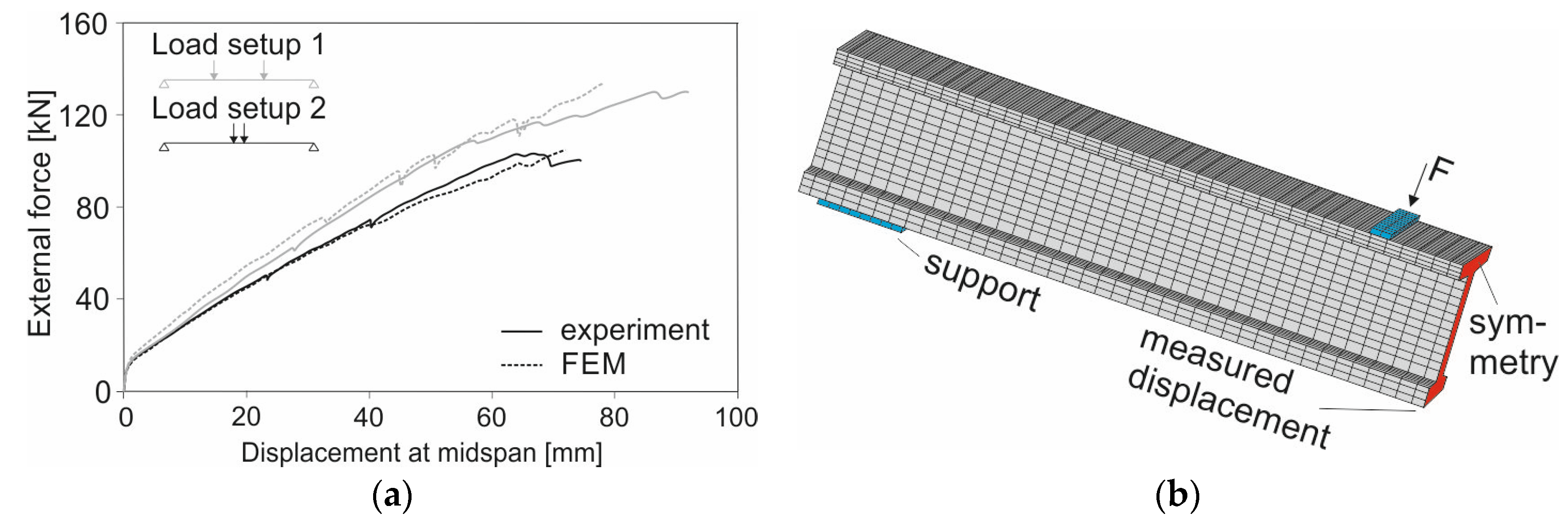
One other well-known method for calculation is the use of the finite element method (FEM). In Figure 7, experimentally determined and numerically calculated load-deflection curves for the I-beam (Figure 3) are shown for comparison. The CRC beam was experimentally tested at the OML with 2 different load settings (Figure 7). To achieve more information about the I-beam and the interaction between the different components of the beam (concrete, carbon grids, rebars made of AR glass fibers), this structure was recalculated with the FE program ANSYS. As it can be seen in Figure 7, the load-carrying behavior and the failure modes can be simulated. In both cases, the failure was induced by exceeding the concrete’s compressive strength in the compression zone caused by the bending moment. Moreover, with the FEM simulation further investigation were done, e.g., the influence of carbon grids in the compression zone was considered.
4. Conclusions and Outlook
In this paper different concepts of CRC ceiling elements were described, which were designed and tested at the Technische Universität Dresden. With these CRC structures it can be shown that carbon reinforced concrete is a high potential composite material which can already be more than just an alternative to conventional RC structures. This paper wants to give suggestions how the composite material can be used and what the advantages of CRC can be—e.g., it can be built slimmer, more lightweight and durable. Moreover it was shown that CRC elements can be recalculated for flexural failure quite accurate and that those structures can be simulated compared to conventional RC with well-known FE programs as well.
References
- Schladitz, F.; Tietze, M.; Lieboldt, M.; Schumann, A.; Garibaldi, M.P.; Curbach, M. Carbon reinforced concrete in construction practice. In Proceedings of the IABSE Conference—Engineering the Developing World, Kuala Lumpur, Malaysia, 25–27 April 2018. [Google Scholar]
- Rizalla, S.H.; Tadros, G. FRP for prestressing of concrete bridges in Canada. ACI Spec. Publ. 2003, 215, 75–90. [Google Scholar]
- Peled, A.; Bentur, A.; Mobasher, B. Textile Reinforced Concrete (Modern Concrete Technology); CRC Press: Boca Raton, FL, USA, 2017. [Google Scholar]
- Scheerer, S.; Chudoba, R.; Garibaldi, M.P.; Curbach, M. Shells Made of Textile Reinforced Concrete—Applications in Germany. J. Int. Assoc. Shell Spat. Struct. (J. IASS) 2017, 58, 79–93. [Google Scholar] [CrossRef]
- Rempel, S.; Kulas, C.; Will, N.; Bielak, J. Extremely Light and Slender-Precast Pedestrian-Bridge Made Out of Textile-Reinforced Concrete (TRC). In High Tech Concrete: Where Technology and Engineering Meet, Proceedings of the 2017 Fib Symposium, Maastricht, The Netherland, 12–14 June 2017; Springer: Cham, Switzerland.
- Schumann, A.; Michler, H.; Schladitz, F.; Curbach, M. Parking slabs made of carbon reinforced concrete. Struct. Concr. 2018, 19, 647–655. [Google Scholar] [CrossRef]
- Homepage C³-project. Available online: www.bauen-neu-denken.de (accessed on 30 April 2018).
- Schneider, K.; Butler, M.; Mechtcherine, V. Carbon Concrete Composites C³—Nachhaltige Bindemittel und Betone für die Zukunft. Beton-und Stahlbetonbau 2017, 112, 784–794. [Google Scholar] [CrossRef]
- Homepage. Available online: https://tu-dresden.de/bu/bauingenieurwesen/imb/forschung/Forschungsfelder/TRC-C3/C3-vorhaben/C3-B2 (accessed on 30 April 2018).
- Schneider, K.; Butler, M.; Mechtcherine, V. Carbon Concrete Composites C³—Nachhaltige Bindemittel und Betone für die Zukunft. Beton-und Stahlbetonbau 2017, 112, 784–794. [Google Scholar] [CrossRef]
- May, S.; Michler, H.; Schladitz, F.; Curbach, M. Lightweight ceiling system made of carbon reinforced concrete. Struct. Concr. 2018, 1–11. [Google Scholar] [CrossRef]
- Hegger, J.; Will, N. Textile-reinforced concrete: Design models. In Textile Fiber Composites in Civil Engineering; Triantafillou, T.C., Ed.; Woodhead Publishing: Sawston, UK; Elsevier Ltd.: New York, NY, USA, 2016; pp. 189–207. [Google Scholar]
Figure 1.
Shaped grid made of carbon fibers [mm]: (a) Principal drawing; 1—fine-grained concrete, 2—grid in shape of a loop, 3—steel beam as a support, lb—available end anchorage length; (b) manufactured shape loop before casting the parking slab (graphic and photo: A. Schumann).
Figure 1.
Shaped grid made of carbon fibers [mm]: (a) Principal drawing; 1—fine-grained concrete, 2—grid in shape of a loop, 3—steel beam as a support, lb—available end anchorage length; (b) manufactured shape loop before casting the parking slab (graphic and photo: A. Schumann).
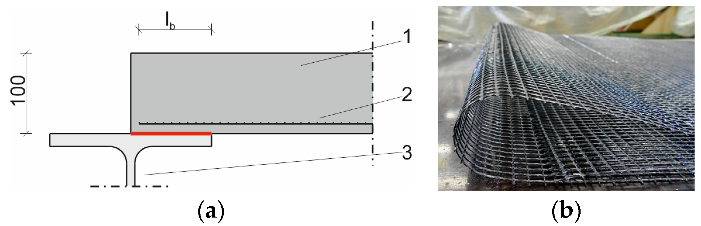
Figure 2.
Testing the parking slab: (a) test setup; (b) experimental load-deflection curve, deflection was measured at the half of the span (graphic and photo: A. Schumann).
Figure 2.
Testing the parking slab: (a) test setup; (b) experimental load-deflection curve, deflection was measured at the half of the span (graphic and photo: A. Schumann).
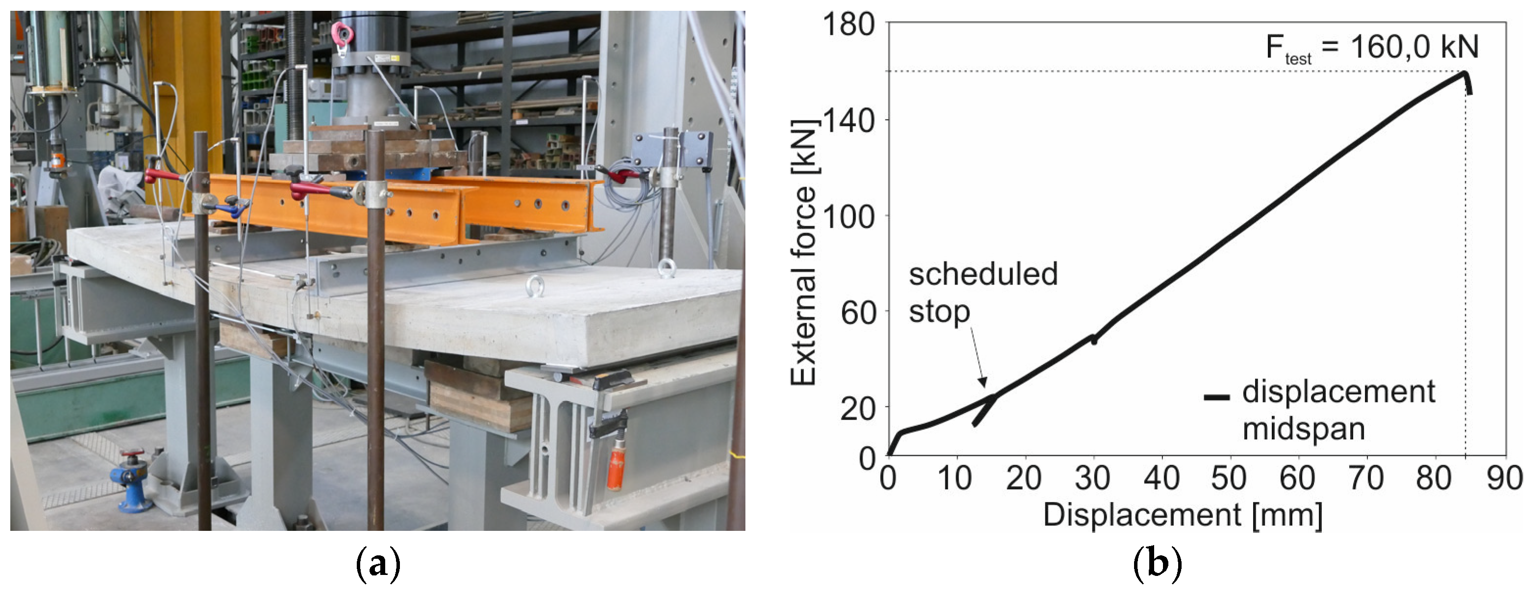
Figure 3.
Comparison between (left) a RC and (right) a TRC beam (photo: A. Schumann).
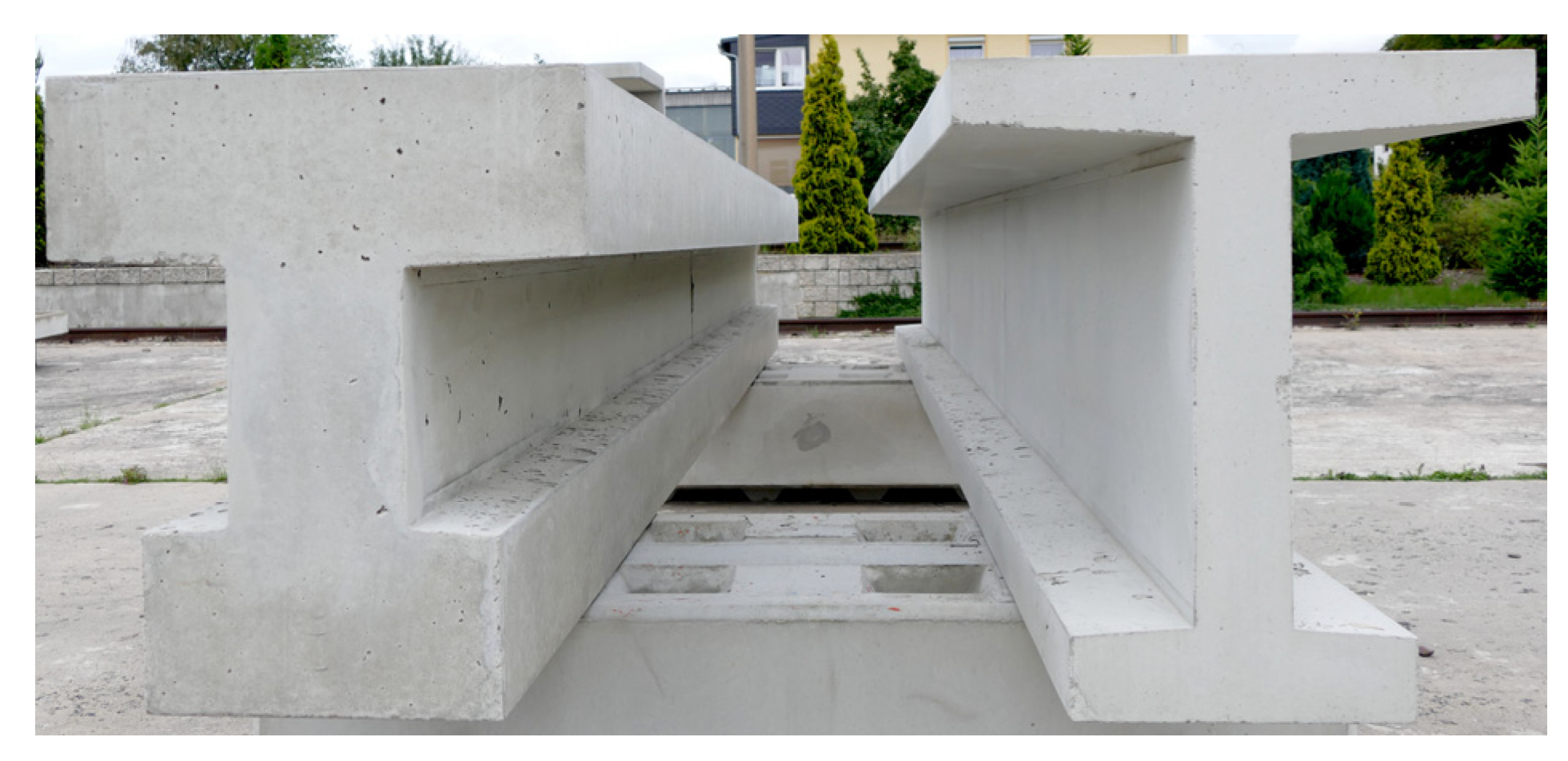
Figure 4.
Cross sections of the I-beams [cm/mm], left: TRC with rebars made of AR glass fibers (blue lines) and carbon grids (black), right: RC with steel reinforcement (graphic: A. Schumann).
Figure 4.
Cross sections of the I-beams [cm/mm], left: TRC with rebars made of AR glass fibers (blue lines) and carbon grids (black), right: RC with steel reinforcement (graphic: A. Schumann).
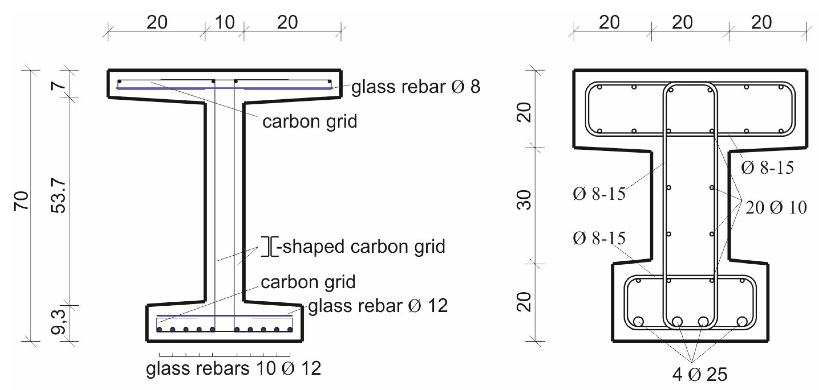
Figure 5.
Shell-like CRC slab [cm]: (a) bottom view; (b) experimental load-deflection curve, deflection was measured at the half of the span; (c) cross-section of the element in midspan (graphic and photos: S. May).
Figure 5.
Shell-like CRC slab [cm]: (a) bottom view; (b) experimental load-deflection curve, deflection was measured at the half of the span; (c) cross-section of the element in midspan (graphic and photos: S. May).
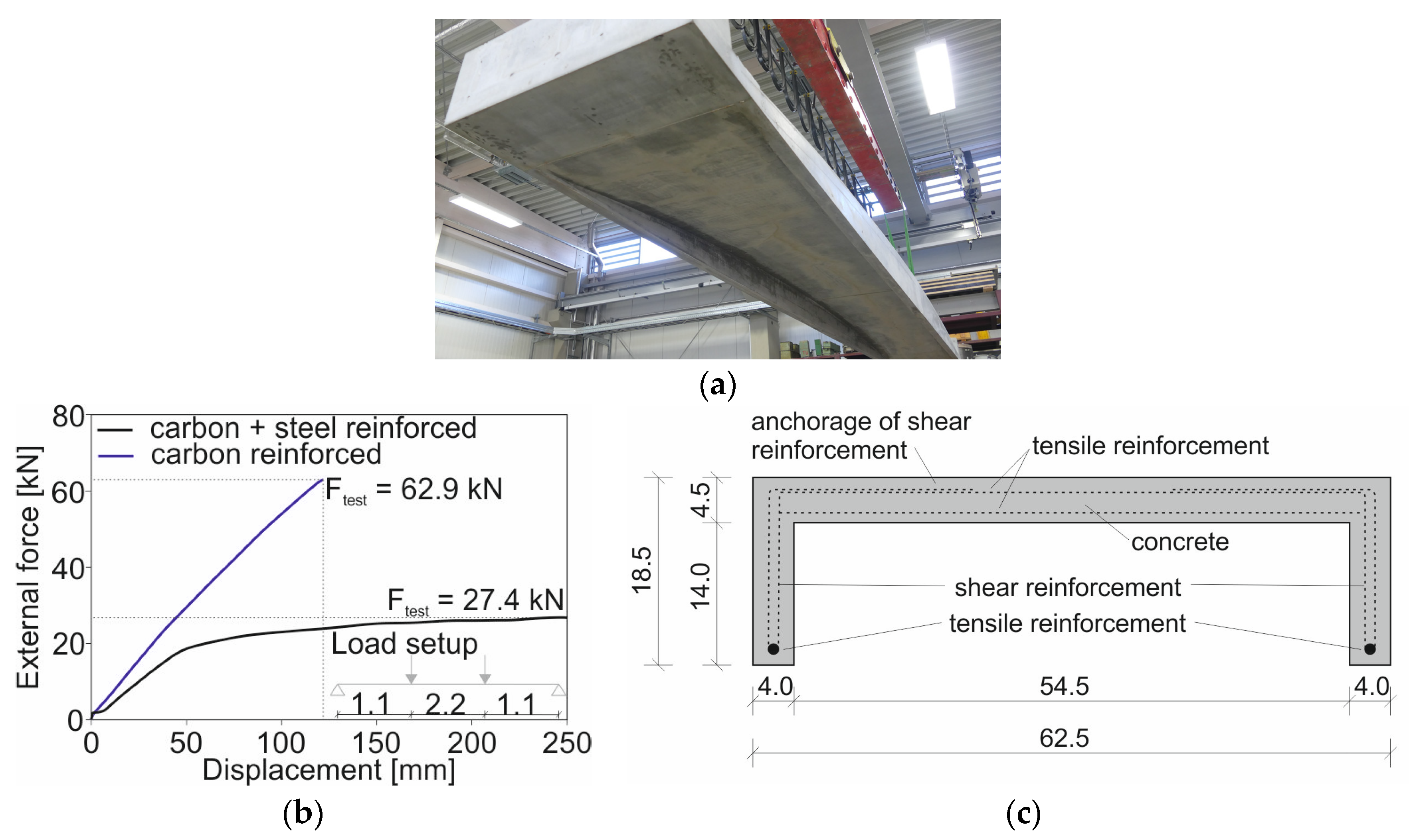
Figure 6.
Ribbed slap made of CRC [cm]: (a) demolition of the demonstrator; (b) cross-section; (c) ceiling element during the experimental test at OML; (d) experimental load-deflection curve, deflection was measured at the half of the span (graphic and photos: J. Kortmann/S. May).
Figure 6.
Ribbed slap made of CRC [cm]: (a) demolition of the demonstrator; (b) cross-section; (c) ceiling element during the experimental test at OML; (d) experimental load-deflection curve, deflection was measured at the half of the span (graphic and photos: J. Kortmann/S. May).
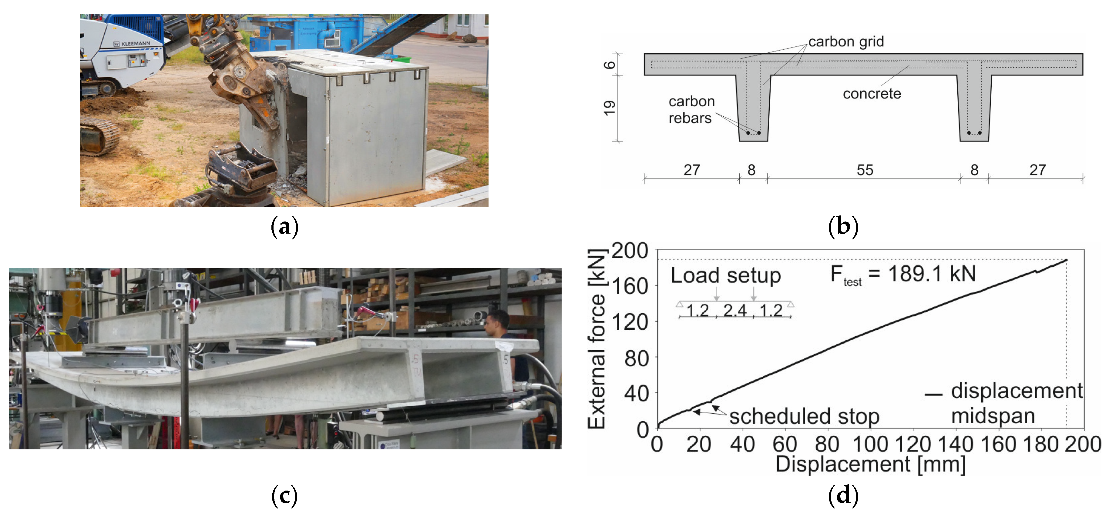
Figure 7.
Comparison between FEM and experimental results for ceiling element 2: (a) load-displacement curve; (b) FE model in ANSYS (graphics: A. Schumann).
Figure 7.
Comparison between FEM and experimental results for ceiling element 2: (a) load-displacement curve; (b) FE model in ANSYS (graphics: A. Schumann).
Publisher’s Note: MDPI stays neutral with regard to jurisdictional claims in published maps and institutional affiliations. |
© 2018 by the authors. Licensee MDPI, Basel, Switzerland. This article is an open access article distributed under the terms and conditions of the Creative Commons Attribution (CC BY) license (https://creativecommons.org/licenses/by/4.0/).
Share and Cite
MDPI and ACS Style
Schumann, A.; May, S.; Curbach, M. Design and Testing of Various Ceiling Elements Made of Carbon Reinforced Concrete. Proceedings 2018, 2, 543. https://doi.org/10.3390/ICEM18-05436
AMA Style
Schumann A, May S, Curbach M. Design and Testing of Various Ceiling Elements Made of Carbon Reinforced Concrete. Proceedings. 2018; 2(8):543. https://doi.org/10.3390/ICEM18-05436
Chicago/Turabian StyleSchumann, Alexander, Sebastian May, and Manfred Curbach. 2018. "Design and Testing of Various Ceiling Elements Made of Carbon Reinforced Concrete" Proceedings 2, no. 8: 543. https://doi.org/10.3390/ICEM18-05436