1. Introduction
Shock tubes are increasingly used to study the dynamic response of blast-loaded plates [
1,
2,
3,
4,
5]. The response of blast-loaded plates may strongly depend upon the intensity of the loading. Thus, to study the interaction between the loading and the plate during blast events, it is essential to be able to generate a repeatable blast loading having well-defined initial and boundary conditions.
The shock tube technique is well known within the field of gas dynamics, and serves as a well-defined and easily controllable alternative to explosive detonations. This study considers a compressed-gas-driven shock tube, in which a high-pressure chamber is separated from a low-pressure chamber using multiple diaphragms. A sudden opening of the diaphragms generates a shock wave travelling down the tube and into the low-pressure chamber. By using a relatively small ratio between the lengths of the high-pressure and low-pressure chambers, this experimental setup differs from traditional shock tubes in the way that the reflected rarefaction waves catch up with the shock wave resulting in pressure profiles similar to the blast wave from an explosive detonation [
5,
6]. The distant flow field is characterized by the occurrence of a normal shock front, i.e., at distances larger than 10× diameter downstream the diaphragms. However, it is important to keep in mind that the flow field may be highly influenced by the diaphragm failure process in the vicinity of the diaphragms [
7,
8]. Failure of the diaphragms often initiates at the centre and propagates to the edges during tearing and folding of petals. The gas flow therefore starts as a jet and increases in diameter as the diaphragms open until the cross-section of the tube is completely filled. The imperfect burst of a diaphragm therefore results in multi-dimensional disturbances that can significantly modify the flow field predicted by the idealized theory and a complete opening is seldom observed in shock tube experiments. Recent experimental and numerical work on shock tube performance using steel diaphragms suggests that the deviation from idealized theory (i.e., a complete and instantaneous opening of the diaphragm) in terms of loss in intensity of the blast pressure could be in the range of 50–60% [
3].
This work is a continuation of previous studies [
4,
5,
9,
10,
11], which have shown that such a test facility is capable of generating blast-like pressure histories on aluminium and steel plates. However, the previous studies have not been able to fully address the observed loss in directional energy during testing. This study therefore presents recent findings on the influence of the diaphragm failure process on the blast wave formation in the tube. Numerical simulations are used in an attempt to obtain more insight into the underlying physics governing the experimental observations, since the diaphragm failure is a complicated process which is challenging to quantify experimentally. The numerical simulations are performed in the finite element code EUROPLEXUS [
12], and the findings are presented in terms of performance diagrams with respect to the length and firing pressure in the high pressure chamber.
2. Shock Tube Experiments
The tests were performed in the SIMLab Shock Tube Facility (SSTF) at NTNU. A detailed presentation of the design, evaluation of its performance and the experimental programme used herein can be found in Ref. [
5]. However, the experimental setup and programme are briefly repeated in the following for completeness since most of these tests served as the basis for the present work. The SSTF has proven to be an easily controllable alternative to explosive detonations and can be used to study the dynamic response and fluid-structure interaction (FSI) of blast-loaded plates (see e.g., [
4,
5,
9,
10,
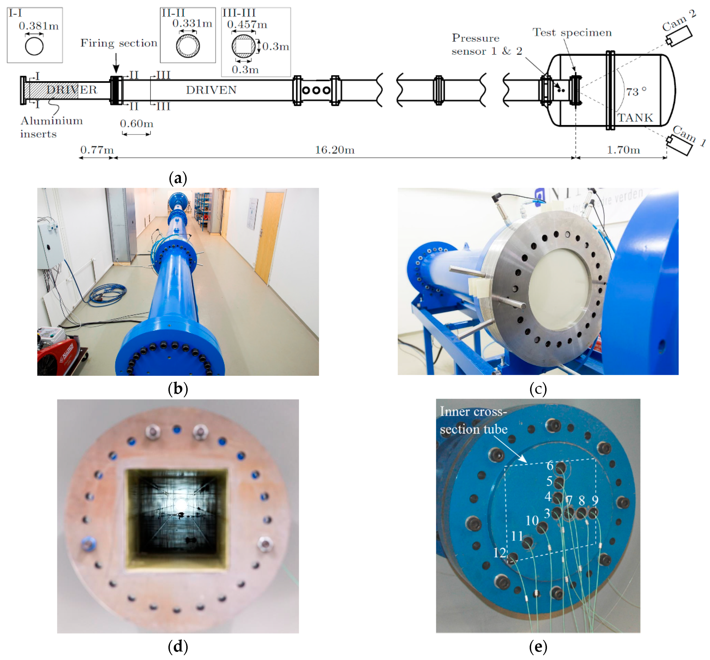
11]). Several parts are joined together using bolted connections of 24 M24 socket-head screws at the end flanges of each part (
Figure 1a,b). Rubber O-rings are recessed into the flange surfaces to ensure sealing at the joints. The overall length of the tube is 18.355 m and it is made from stainless steel of grade P355NH which is intended for pressure purposes according to the EN 13445.
The high-pressure chamber (called driver in
Figure 1a) is manufactured with a total length of 2.02 m and has an inner diameter of 0.331 m where the internal wall is dull polished to obtain a smooth surface. Aluminium inserts may be used to vary the length of the driver section in 0.25 m increments. The driver is followed by a 0.14-m-long firing section which consists of several intermediate pressure chambers separated by diaphragms (
Figure 1a,c). This enables the total pressure difference between the driver and driven section to be achieved stepwise. The test starts by filling the driver and firing section with compressed air, where the pressures in the intermediate chambers are operated below the diaphragm rupture strength such that the desired pressure is obtained in the driver. Rupture of the diaphragms is initiated by controlled and rapid venting of the intermediate pressure closest to the driver section, using two solenoid valves (ASCO Series 223). This ensures a controlled rupture of the diaphragms and reproducible bursting pressures. The bursting pressure may be varied by changing the thickness of the diaphragms. Melinex sheets are used as diaphragms due to its strength and repeatability.
The inner cross-section in the driven section starts with a 0.6-m-long transition region from circular to a square cross-section (
Figure 1a), where an epoxy material is used to obtain a smooth surface and a square cross-section of 0.3 m × 0.3 m inside the surrounding tube (
Figure 1d). The epoxy material works as a practically incompressible material while the surrounding tube ensures the structural strength. The average roughness (Ra) of the surfaces inside the driven section is reported by the manufacturer to be in the range of 0.2–0.4
m.
In the present work, the length of the driver and driven sections was 0.77 m and 16.195 m, respectively. The blast intensity was varied by changing the pressure in the driver section, while the pressure in the driven section was at ambient conditions.
Table 1 gives the test matrix used herein, where each test is numbered R77-Y in which Y indicates the firing overpressure in bars in the driver, R denotes rigid massive plate at the rear end and 77 is the driver length in centimeters. The massive plate was used to obtain a rigid blind flange and equipped with 10 pressure gauges along the horizontal, vertical and diagonal (
Figure 1e). Piezoelectric pressure sensors (Kistler 603B) were used to measure the pressure on the massive plate with a sampling frequency of 500 kHz. The measurements of the reflected pressure on the massive plate are already reported in Ref. [
5], and will be used as basis to investigate the influence of the diaphragm failure process.
3. Numerical Simulations
Numerical simulations were used in an attempt to study the influence of the diaphragm failure on the blast wave formation in the shock tube tests. The inner cross section of the tube was modelled using cell-centered finite volumes (CCFV) with a mesh size of 10 mm, according to the mesh sensitivity study in Ref. [
5]. The 3D mesh starts with a circular cross section in the driver and firing sections. Then a transition part of 0.6 m length follows immediately downstream the diaphragms, which starts with the circular cross-section in the driver and ends with the square cross-section in the driven throughout the remaining part of the tube (
Figure 1a). The air was modelled using the equation-of-state for the ideal gas material (GAZP) [
12] and the initial conditions for each simulation were taken from the tests in
Table 1. The conservation laws of mass, momentum and energy were then expressed in a spatial framework. This Eulerian formulation considers the computational mesh fixed while the fluid (particles) moves relative to these grid points. The numerical fluxes between adjacent CCFVs were calculated using the approximate Harten-Lax-van-Leer-Contact (HLLC) Riemann solver [
12], where stability in the convection phase of the explicit solution in time was ensured by using a Courant-Friedrichs-Lewy (CFL) coefficient of 0.5.
The diaphragms were modelled using a Lagrangian discretization with an element size of approximately 10 mm as the base mesh and 4-node Reissner-Mindlin shells (Q4GS) with 6 dofs per node and 20 integration points (5 through the thickness). Based on the information from the manufacturer, the diaphragms were assumed to behave elasto-plastically until failure. Depending on the thickness of the diaphragms, the yield stress and plastic modulus were in the range of 100–160 MPa and 13.9–54.7 MPa, respectively. Failure was modelled using element erosion and was initiated when all the integration points in the respective element reached the critical value of 100% for the maximum principle strain. In an attempt to predict the crack propagation observed in the experiments, it was used adaptive mesh refinement (AMR) driven by the plastic strain . That is, the mesh refinement occurs at user-defined levels of the plastic strain and at successive levels of refinement. This study used up to two successive refinements within the range of , resulting in a minimum element size of 2.5 mm when .
The diaphragms are completely decoupled from the fluid during the filling process. That is, the diaphragms are first loaded by an externally imposed pressure similar to that of the compressed air in the driver. Once equilibrium is reached around the deformed configuration, the externally imposed pressure is removed and the fluid states are initialized in the driver, intermediate and driven chambers. The pressure gradients over the diaphragms will then ensure equilibrium until rapid venting of the firing section initiates the diaphragm failure process. An embedded FSI technique (FLSW) [
12] was used for the coupling at the fluid-diaphragm (F-D) interface and FSI-driven AMR was also activated in the fluid sub-domain to obtain a sufficiently refined fluid mesh at the F-D interface.
In particular, two effects of the diaphragm failure process were considered. First, the diaphragms were allowed to deform until maximum deformation where the diaphragms were eroded completely from the simulation before undergoing any failure. These simulations indicate the effect of the increasing volume in the driver section due to the compression of air resulting in deformation of the diaphragms. Then, the simulations were re-run by also including the subsequent diaphragm failure process.
The results from these simulations are compared to the experimental data and the idealized 1D simulations in Ref. [
5] in
Figure 2 and
Figure 3. As expected, the 3D simulations with increased volume in the driver section, due to the diaphragm deformation, predicts larger blast intensities than the idealized 1D simulations. It is evident that including the diaphragm failure process results in a blast wave formation significantly closer to the experimental observations when comparing to the idealized 1D simulations. The diaphragm failure process also seems to have an influence on the secondary reflection occurring at approximately 40 ms in
Figure 3b. It is noted that the blast parameters are overestimated at the largest blast intensities (R77-60 and R77-75 in
Figure 2a,b).
4. Concluding Remarks
The influence of the diaphragm failure process on the blast wave formation in the SIMLab Shock Tube Facility was studied numerically and compared to experimental results. Blast intensities were reported in terms of the reflected pressure histories measured on a massive steel plate acting as a blind flange at the end of the tube. The numerical simulations indicate that the observed loss of directional energy in the distant flow field may be due to the diaphragm failure process, resulting in a multi-dimensional flow in the vicinity of the diaphragms. The findings in this study are important to understand how such a facility works, especially if FSI effects during the dynamic response of flexible plates are of interest. It is necessary to obtain an accurate prediction of the loading itself, before moving on to FSI studies on flexible plates.
It is believed that the overestimation of the largest blast intensities in the numerical model is because this study neglects the effects of friction and heat exchange against the interior walls of the tube. This will be investigated in more detail in a subsequent study. This subsequent study will also evaluate the performance of the numerical model for other driver lengths, using the same diaphragm combinations and firing pressures as in this study.
Author Contributions
This work is a continuation of the PhD work of V.A., supervised by M.L. and T.B. V.A. performed the numerical simulations in close collaboration with F.C. and G.V. who established and carried out new implementations in EUROPLEXUS. V.A. wrote the manuscript with input from all authors.
Acknowledgments
This work has been carried out with financial support from NTNU and the Research Council of Norway through the Centre for Advanced Structural Analysis (CASA), Centre for Research-based Innovation (Project No. 237885). The financial support by the Norwegian Ministry of Justice and Public Security is also greatly appreciated.
Conflicts of Interest
The authors declare no conflict of interest.
References
- Lloyd, A.; Jacques, E.; Saatcioglu, M.; Palermo, D.; Nistor, I.; Tikka, T. Capabilities of a shock tube to simulate blast loading on structures. ACI Spec. Publ. 2010, 281, 35–54. [Google Scholar]
- Colombo, M.; Di Prisco, M.; Martinelli, P. A new shock tube facility for tunnel safety. Exp. Mech. 2011, 51, 1143–1154. [Google Scholar] [CrossRef]
- Andreotti, R.; Colombo, M.; Guardone, A.; Martinelli, P.; Riganti, G.; Di Prisco, M. Performance of a shock tube facility for impact response of structures. Int. J. Non-Linear Mech. 2015, 72, 53–66. [Google Scholar] [CrossRef]
- Aune, V.; Børvik, T.; Langseth, M. Behaviour of plated structures subjected to blast loading. EPJ Web of Conferences 2015, 94, 01015. [Google Scholar] [CrossRef]
- Aune, V.; Fagerholt, E.; Langseth, M.; Børvik, T. A shock tube facility to generate blast loading on structures. Int. J. Protective Struct. 2016, 7, 340–366. [Google Scholar] [CrossRef]
- Tasissa, A.F.; Hautefeuille, M.; Fitek, J.H.; Radovitzky, R.A. On the formation of Friedlander waves on a compressed-gas-driven shock tube. Proc. R. Soc. A 2016, 472, 20150611. [Google Scholar] [CrossRef] [PubMed]
- Payman, W.; Shepherd, W.C.F. Explosion waves and shock waves. VI. The disturbance produced by bursting diaphragms with compressed air. Proc. R. Soc. A 1946, 186, 293–321. [Google Scholar]
- White, D.R. Influence of diaphragm opening time on shock-tube flow. J. Fluid Mech. 1958, 4, 585–599. [Google Scholar] [CrossRef]
- Aune, V.; Valsamos, G.; Casadei, F.; Langseth, M.; Børvik, T. On the dynamic response of blast-loaded steel plates with and without pre-formed holes. Int. J. Impact Eng. 2017, 108, 27–46. [Google Scholar] [CrossRef]
- Aune, V. Behaviour and Modelling of Flexible Structures Subjected to Blast Loading. Ph.D. Thesis, Norwegian University of Science and Technology, Trondheim, Norway, 2017. [Google Scholar]
- Aune, V.; Valsamos, G.; Casadei, F.; Larcher, M.; Langseth, M.; Børvik, T. Use of damage-based mesh adaptivity to predict ductile failure in blast-loaded aluminium plates. Procedia Eng. 2017, 197, 3–12. [Google Scholar] [CrossRef]
- EUROPLEXUS. Available online: http://europlexus.jrc.ec.europa.eu/ (accessed on 25 April 2018).
| Publisher’s Note: MDPI stays neutral with regard to jurisdictional claims in published maps and institutional affiliations. |
© 2018 by the authors. Licensee MDPI, Basel, Switzerland. This article is an open access article distributed under the terms and conditions of the Creative Commons Attribution (CC BY) license (https://creativecommons.org/licenses/by/4.0/).


