Experimental Study on the Strength of Stainless Steel Fillet Welds †

1
PhD Fellowship of the Research Foundation Flanders, Department of Civil Engineering, KU Leuven, 2860 Sint-Katelijne-Waver, Belgium
2
Department of Mechanical Engineering, KU Leuven, 2860 Sint-Katelijne-Waver, Belgium
3
Department of Materials Engineering, KU Leuven, 9000 Ghent, Belgium
4
Department of Civil Engineering, KU Leuven, 2860 Sint-Katelijne-Waver, Belgium
*
Author to whom correspondence should be addressed.
†
Presented at the 18th International Conference on Experimental Mechanics (ICEM18), Brussels, Belgium, 1–5 July 2018.
Proceedings 2018, 2(8), 431; https://doi.org/10.3390/ICEM18-05290
Published: 8 June 2018
(This article belongs to the Proceedings of The 18th International Conference on Experimental Mechanics)
Abstract
:This paper describes 18 tensile tests performed on welded specimens made of 3 stainless steel grades: EN 1.4307 (304L) and EN 1.4404 (316L) austenitic grades and EN 1.4062 duplex grade. For each grade, 3 tests were carried out parallel to the weld causing shear stresses (in the weld throat plane, parallel to the weld throat axis) and 3 tests along the transverse direction, perpendicular to the weld, causing a combination of normal (perpendicular to the weld throat plane) and shear (in the weld throat plane, perpendicular to the weld throat axis) stresses. The digital image correlation (DIC) technique was used to measure the fracture surface. Based on these experiments, an assessment of the current design rules was made.
1. Introduction
Recently, stainless steels, and more specifically duplex grades, are increasingly used in load-bearing elements in the construction and transport sectors because those grades combine aesthetic appearance, excellent mechanical properties and corrosion resistance. Those grades are used in structural components in bridges, such as the Cala Galdana bridge in Menorca, the Siena Bridge in Ruffolo or the Millenium Bridge in York [1]. The components included in these applications can include both open or closed cross-sections which are, most of the time, fabricated cross-sections. Various studies show that the weldability of stainless steel is good and that most grades can be welded with all commonly used welding processes, provided that appropriate rules are followed [2]. However, research on the strength of stainless steel welds is rather scarce as only 46 experiments are today available in the literature [3].
In practice, welds are designed by comparing the Von Mises stress in the weld throat plane to the ultimate strength fu of the base metal. The latter is divided by a correlation factor βw 1.0, taking into account the variety of carbon steel grades. For all stainless steel grades, EN 1993-1-4 [4] prescribes βw = 1.0. However, current research [5] suggests that a correlation factor βw smaller than 1.0 could be used for S460 carbon steel, which’s strength is comparable to the presently studied duplex grade.
2. Welding Process and Procedure
All fillet welds were produced using manual gas metal arc welding (GMAW). The pulse arc mode guarantees a sound penetration with a lower heat input. The corresponding filler material for a stainless steel grade is chemically overmatched to ensure corrosion resistance, but mechanically matched to ensure structural integrity. For the tests performed during this study, the filler materials mentioned in Table 1 were used. For the EN 1.4307 grade, no corresponding filler material (type 304) exists. Typically, a type 308 filler material is used to weld this metal but, due to availability issues, a type 309 filler material was presently used instead. This should not influence the experimental results because the difference between both fillers’ mechanical behaviour is limited. The EN 1.4307 and EN 1.4404 grades were both welded with an argon-based shielding gas, supplemented with 2.5% CO2, while Arcal 129 gas, which is an argon-based shielding gas with 1.7% nitrogen, 5% CO2 and 1.8% helium, was used for the EN 1.4062 grade.
The heat input was calculated from the measured voltage, current and travel speed, combined with the efficiency factor for the gas metal arc welding process (80%). The heat input is especially important when welding duplex stainless steels as it determines—together with other factors as the workpiece geometry or the preheat temperature—the cooling rate and thus the austenite-ferrite balance of the material. For the used duplex grade, a heat input ranging between 0.5 and 1.5 kJ/mm is recommended in [2]. The welding parameters, summarized in Table 1, were tested on pre-production test pieces, on which visual testing, microstructural investigation and hardness testing were performed.
The pre-production test pieces were cut, polished and etched for microstructural investigation. Test pieces made of EN 1.4307 and EN 1.4404 were chemically etched with an acidified ferric chloride solution, while EN 1.4062 was electrolytically polished with A3 elektrolyte and afterwards etched with a Lichtenegger and Bloech solution. Microstructural investigation is particularly important for the EN 1.4062 samples, as the austenite-ferrite balance plays an important role on the mechanical and corrosion-related characteristics of the material. For example, high ferrite contents can lead to brittle behaviour. This balance was measured by pixel counting with ImageJ software [7] based on 30 microscopic images, according to ASTM E 562 [8], taken with a Hirox KH-8700 digital optical microscope with a magnification of 1000×. The results, together with the recommended values according to [9], are summarized in Table 2.
The visual inspection revealed imperfections that fall within the limits of quality level B, except for intermittent undercut, which locally was inferior to quality level D, as mentioned in EN ISO 5817 [10]. However, later in this paper, it is shown that this will have no influence on the ultimate load. The Vickers hardness measurements showed a relative constant hardness level in the base metal and weld metal with a maximum difference of 8%. More information on the welding procedure and the subsequent quality assessment can be found in [11].
3. Experimental Programme
This study and the ones included in [11,12] concentrates on fillet welds with two loading directions and three stainless steel grades i.e., two austenitic grades, EN 1.4307 (304L) and EN 1.4404 (316L), and one duplex grade, EN 1.4062. Half of the tests were carried out with the load perpendicular to the welds causing both normal stress σ⊥ (perpendicular to the weld plane) and shear stress τ⊥ (perpendicular to the weld throat axis) and the other half of the tests with the load parallel to the weld causing only shear stress τ// (parallel to the weld throat axis). During the test, all deformations were measured using digital image correlation (DIC). Furthermore, a shape reconstruction utilizing DIC was used to measure the effective fracture area. The interested reader can find more about the DIC techniques in [13] and [14].
3.1. Mechanical Properties of the Base Metal
One of the essential parameters in the design of welded components is the strength of the weakest joined part. The effect of the strength of the filler material on the strength of the weld is neglected in this study as proposed in the design recommendations of EN 1993-1-4 [5]. For each stainless steel grade, three dog-bone coupons, cut in the same direction as the welded specimens, were tested under tension. The two austenitic grades EN 1.4307 and EN 1.4404 exhibit a large ductility domain and significant strain hardening compared to the duplex grade EN 1.4062, which has a considerably higher yield strength (501 MPa compared to 284 MPa and 280 MPa for EN 1.4307 and for EN 1.4404, respectively) combined with a smaller but still considerable strain hardening domain. For more information on the stress-strain behaviour of stainless steel, the reader can refer to [11,15].
3.2. Experimental Results
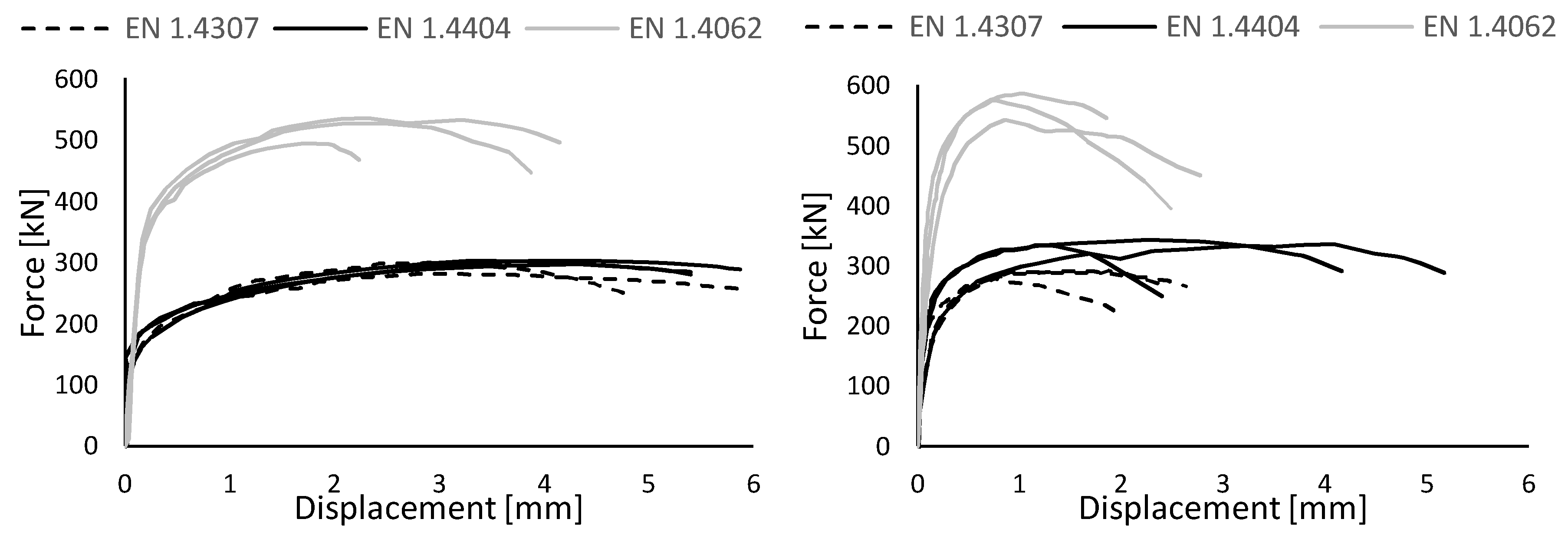
All tensile tests were performed using a hydraulic tensile testing device with a maximum capacity of 1000 kN. The load was applied quasi statically with an average speed lower than 0.01 mm/s. The displacements fields were measured optically using two stereo vision DIC systems, one for the bottom welds and one for the top welds, on one side of the specimen. The load-displacement curves deduced from those measurements can be found in Figure 1.
As can be seen from Figure 1, all failure modes were ductile. All cracks initiated in the start or end zone of the weld (in the end crater for most welds) and propagated until failure was reached. Typical failure modes for a longitudinal and a transverse weld can be seen in Figure 2. In general, the welds failed in the fusion zone at an angle ranging between 30° and 50° measured from the plate surface. Because the failure occurs in the weld metal, the intermittent undercut, which is visible in some welds, did not influence the ultimate load.
4. Assessment of the Design Rules
The area of the weld throat plane has a direct influence on the ultimate strength of the weld. In reality, the weld throat height varies along the length of the weld, especially in the start and end zone where a divergence to the design value could be noticed. Furthermore, a deep penetration of the weld in the base material significantly increases the strength of the weld. In the macroscopic investigation, a large penetration up to 2.5 mm for the EN 1.4404 specimens was noticed. It is therefore important to measure the actual fracture surface rather than just base the experimental stress on the theoretical 45° weld throat plane area. After the test, the fracture surface was speckled and measured by taking static pictures of it using DIC. A pointcloud on this surface was then generated using MatchID [16], the software used for taking and post-processing the DIC pictures. Afterwards, a post processing software, in this case CloudCompare [17], was used to calculate the area of the meshed cloud of points. The results of these measurements, together with the experimental and design ultimate loads, are provided in Table 3. For the assessment of the design ultimate loads, the safety factor is taken as 1.0. It is worth noting that, in the evaluation of the design ultimate loads, the ultimate engineering strength fu is used together with the actual failure surface. While, for reason of consistency, the true stress should be used everywhere.
First, from Table 4, one can notice a clear difference in strength between the two loading directions. It reaches, on average, 19% for the austenitic grades and 6% for the duplex grade. This difference was noticed by numerous authors in the literature [3,5,18,19].
Second, for all three grades, the experimental-to-predicted strength ratios are on the safe side. The tests on welds loaded in the transverse direction show an average overestimation of 27% while the welds loaded in the longitudinal direction show 12% of conservatism. Further research is still needed to investigate the degree of conservatism of the current design rules when using a lower correlation factor for all stainless steel grades in all loading directions. An ongoing test campaign on duplex stainless steel longitudinal and transverse welds, including various welding processes will supplement the presented study and allow for a full statistical evaluation in the near future.
Third, the difference in ultimate strengths among the different grades originates from both the mechanical behaviour of the base material and of the filler material. The influence of the strength of the consumable on the ultimate strength of the weld was disregarded in this study. However, in the literature [18], it was shown that the effect of the mechanical properties of the welding consumable has an influence on the strength ratio. It is also evidenced herein by the comparison of the strength ratios of both austenitic grades showing an average strength ratio of 1.01 and 1.16 for the longitudinal direction for respectively the EN 1.4307 and 1.4404 grade, while both base metals exhibit very similar stress-strain behaviour [11].
5. Conclusions
In this paper, the applicability of the design rules in EN 1993-1-4 [5] and EN 1993-1-8 [6] is assessed based on 18 experiments on stainless steel welded specimens. The experimental programme includes 3 stainless steel grades: austenitic EN 1.4307, also known as 304L, austenitic EN 1.4404, or 316L, and lean duplex EN 1.4062. Two loading directions were tested. The transverse loading direction, causing a combination of normal (perpendicular to the weld throat plane) and shear (in the weld throat plane, perpendicular to the weld throat axis) stresses, clearly showed a higher experimental-to-predicted strength ratio for all grades. The longitudinally loaded specimens, causing shear stresses (in the weld throat plane, parallel to the weld throat axis), showed a lower strength ratio. Based on this preliminary estimation, it could be concluded that the current European design rules [3,6], using a βw of 1.0, give conservative predictions for all grades and loading directions, with an average strength ratio 1.12 for the longitudinal direction and 1.27 for the transverse direction. The average strength ratio for duplex stainless steel specimen suggests that a lower correlation factor βw for these grades should be recommended. More tests with various welding processes are ongoing to allow for a statistical evaluation of the correlation factor βw. Three important parameters will be taken into account: (1) The effect of the mechanical properties of the welding consumable, relative to the base material; (2) the true strength of the base metal; and (3) the angle of the fracture surface to the plate as, presently, Von Mises comparison stress was calculated based on the assumption that this angle equals 45°.
Acknowledgments
The first author is funded by a PhD fellowship from the Research Foundation Flanders. We would also like to thank Industeel for granting the duplex material for this research.
References
- Baddoo, N.R.; Kosmač, A. Sustainable Duplex Stainless Steel Bridges. 2010. Available online: www.wordstainless.org (accessed on 15 June 2018).
- Kotecki, D.J. Some Pitfalls in Welding of Duplex Stainless Steels. Soldagem Insp. 2010, 15, 336–343. [Google Scholar] [CrossRef]
- Stangenberg, H. ECSC Project—Structural Design of Stainless Steel Welded Connections; Final Report; Document WP4.1.5S.02; RWTH Institute of Steel Construction: Aachen, Germany, 2000. [Google Scholar]
- European Committee for Standardization (CEN). Eurocode 3: Design of Steel Structures—Part 1–4: General Rules—Supplementary Rules for Stainless Steels; Brussel CEN: Brussel, Belgium, 2015. [Google Scholar]
- Günther, H.P.; Hildebrand, J.; Rasche, C.; Versch, C.; Wudtke, I.; Kuhlmann, U.; Vormwald, M.; Werner, F. Welded connections of high-strength steels for the building industry. Weld World 2012, 56, 86–106. [Google Scholar] [CrossRef]
- European Committee for Standardization (CEN). Eurocode 3: Design of Steel Structures—Part 1–8: Design of Joints; Brussel CEN: Brussel, Belgium, 2009. [Google Scholar]
- ImageJ (Version 2) [GPL Software]. 2017. Available online: http://www.imagej.net/ (accessed on 15 June 2018).
- ASTM E562-11, Standard Test Method for Determining Volume Fraction by Systematic Manual Point Count; ASTM International: West Conshohocken, PA, USA, 2011.
- Van Nassau, L.; Meelker, H.; Hilkes, J. Welding duplex and super-duplex stainless steels. Duplex Stainl. Steels 1991, 1, 303–323. [Google Scholar]
- ISO 5817, Welding—Fusion-Welded Joints in Steel, Nickel, Titanium and Their Alloys (Beam Welding Excluded)—Quality Levels for Imperfections; Standard, International Organisation for Standardisation: Geneva, Switzerland, 2014.
- Fortan, M.; Dejans, A.; Debruyne, D.; Rossi, B. The strength of stainless steel fillet welds using GMAW. In Proceedings of the Stainless Steel in Structures—Fifth International Experts Seminar, London, UK, 18–19 Spetember 2017. [Google Scholar]
- Maes, A.; Mertens, S. Experimental Study of the Strength of Austenitic and Duplex Welds. Master’s Thesis, KU Leuven Campus De Nayer, Sint-Katelijne-Waver, Belgium, 2017. [Google Scholar]
- Fortan, M.; De Wilder, K.; Debruyne, D.; Rossi, B. Shear buckling of lean duplex stainless steel plate girders with non-rigid end posts. In Proceedings of the 8th International Conference on Steel and Aluminium Structures 2016, Hong Kong, China, 7–9 December 2016. [Google Scholar]
- Sutton, M.A.; Orteu, J.-J.; Schreier, H.W. Image Correlation for Shape, Motion and Deformation Measurements: Basic Concepts, Theory and Applications; Springer: New York, NY, USA, 2009. [Google Scholar]
- Arrayago, I.; Real, E.; Gardner, L. Description of stress-strain curves for stainless steel alloys. Mater. Des. 2015, 87, 540–552. [Google Scholar] [CrossRef]
- MatchID. Available online: www.matchidmbc.be (accessed on 15 June 2018).
- CloudCompare (Version 2.8.1) [GPL Software]. 2017. Available online: http://www.CloudCompare.org/ (accessed on 15 June 2018).
- Kuhlmann, U.; Günther, H.-P.; Rasche, C. High-strength steel fillet welded connections. Steel Constr. 2008, 1, 77–84. [Google Scholar] [CrossRef]
- Lu, H.; Dong, P.; Boppudi, S. Strength analysis of fillet welds under longitudinal and transverse shear conditions. Mar. Struc. 2015, 43, 87–106. [Google Scholar] [CrossRef]
Figure 1.
Load-displacement curves of longitudinal welds (left) and transverse welds (right).

Figure 2.
Typical failure mode for longitudinal welds (left) and transverse welds (right).


Table 1.
Overview of the welding parameters and the resulting heat input.
| Base Material | Filler Material | Travel Speed | Wire Speed | Voltage | Current | Pulse Frequency | Heat Input |
|---|---|---|---|---|---|---|---|
| cm/min | m/min | V | A | Hz | kJ/mm | ||
| 1.4307 | type 309LSi | 30 | 7.5 | 22.2 | 258 | 233 | 0.92 |
| 1.4404 | type 316LSi | 33 | 8.2 | 23 | 265 | 233 | 0.89 |
| 1.4062 | Böhler CN 24/9 LDX | 33 | 7.5 | 21 | 226 | 278 | 0.69 |
Table 2.
Measured and recommended ferrite contents for the EN 1.4062 material in different zones of the welded sample.
Table 2.
Measured and recommended ferrite contents for the EN 1.4062 material in different zones of the welded sample.
| Zone | Measured Ferrite Content and 95% Confidence Interval (%) | Recommended Ferrite Content (%) |
|---|---|---|
| Base material | 64 ± 8 | 40 to 60 |
| Heat affected zone | 70 ± 8 | 25 to 75 |
| Weld metal | 61 ± 2 | 25 to 75 |
Table 3.
Overview of test results and predicted strengths based on engineering fu.
| Name | Load Direction | Measured Fracture Surface | Tensile Strength | Experimental Failure Load | Predicted Failure Load | Strength Ratio |
|---|---|---|---|---|---|---|
| A | fu | Fexp | Fpred | Fexp/Fpred | ||
| - | mm2 | MPa | kN | kN | - | |
| 1.4307L1 | Longitudinal | 192 | 678 | 302 | 301 | 1.00 |
| 1.4307L2 | Longitudinal | 188 | 299 | 294 | 1.02 | |
| 1.4307L3 | Longitudinal | 177 | 284 | 278 | 1.02 | |
| 1.4307T1 | Transverse | 258 | 297 | 247 | 1.20 | |
| 1.4307T2 | Transverse | 250 | 281 | 239 | 1.17 | |
| 1.4307T3 | Transverse | 250 | 292 | 240 | 1.22 | |
| 1.4404L1 | Longitudinal | 182 | 609 | 303 | 257 | 1.18 |
| 1.4404L2 | Longitudinal | 183 | 297 | 258 | 1.15 | |
| 1.4404L3 | Longitudinal | 189 | 303 | 266 | 1.14 | |
| 1.4404T1 | Transverse | 290 | 338 | 250 | 1.35 | |
| 1.4404T2 | Transverse | 281 | 337 | 242 | 1.39 | |
| 1.4404T3 | Transverse | 306 | 343 | 263 | 1.30 | |
| 1.4062L1 | Longitudinal | 268 | 711 | 529 | 440 | 1.20 |
| 1.4062L2 | Longitudinal | 250 | 495 | 410 | 1.21 | |
| 1.4062L3 | Longitudinal | 275 | 536 | 451 | 1.19 | |
| 1.4062T1 | Transverse | 479 | 576 | 482 | 1.20 | |
| 1.4062T2 | Transverse | 457 | 587 | 459 | 1.28 | |
| 1.4062T3 | Transverse | 417 | 543 | 420 | 1.29 |
Table 4.
Average strength ratio for each grade and direction.
| Grade | Longitudinal | Transverse | ||
|---|---|---|---|---|
| Average Strength Ratio | CoV | Average Strength Ratio | CoV | |
| EN 1.4307 | 1.01 | 0.01 | 1.20 | 0.02 |
| EN 1.4404 | 1.16 | 0.02 | 1.35 | 0.03 |
| EN 1.4062 | 1.20 | 0.01 | 1.26 | 0.04 |
Publisher’s Note: MDPI stays neutral with regard to jurisdictional claims in published maps and institutional affiliations. |
© 2018 by the authors. Licensee MDPI, Basel, Switzerland. This article is an open access article distributed under the terms and conditions of the Creative Commons Attribution (CC BY) license (https://creativecommons.org/licenses/by/4.0/).
Share and Cite
MDPI and ACS Style
Fortan, M.; Dejans, A.; Debruyne, D.; Rossi, B. Experimental Study on the Strength of Stainless Steel Fillet Welds. Proceedings 2018, 2, 431. https://doi.org/10.3390/ICEM18-05290
AMA Style
Fortan M, Dejans A, Debruyne D, Rossi B. Experimental Study on the Strength of Stainless Steel Fillet Welds. Proceedings. 2018; 2(8):431. https://doi.org/10.3390/ICEM18-05290
Chicago/Turabian StyleFortan, Maarten, Arnout Dejans, Dimitri Debruyne, and Barbara Rossi. 2018. "Experimental Study on the Strength of Stainless Steel Fillet Welds" Proceedings 2, no. 8: 431. https://doi.org/10.3390/ICEM18-05290