Novel Experimental Design for Two-Dimensional Delamination in Fiber-Reinforced Polymer Laminates †


Composite Construction Laboratory (CCLab), École Polytechnique Fédérale de Lausanne (EPFL), CH-1015 Lausanne, Switzerland
*
Author to whom correspondence should be addressed.
†
Presented at the 18th International Conference on Experimental Mechanics. Brussels, Belgium, 1–5 July 2018.
Proceedings 2018, 2(8), 408; https://doi.org/10.3390/ICEM18-05283
Published: 30 May 2018
(This article belongs to the Proceedings of The 18th International Conference on Experimental Mechanics)
Abstract
:The two-dimensional (2D) delamination behavior of composite laminates under quasi-static out-of-plane opening loads has been experimentally investigated. A novel design and experimental set-up for fiber-reinforced polymer (FRP) laminated plates with a circular embedded pre-crack was developed. Increasing load-displacement curves were obtained due to the increasing crack front length during propagation. Throughout the loading process, stiffening and softening mechanisms were activated. The stretching of delaminated part of the laminates constituted the main stiffening mechanism. Once the crack started growing, a corresponding softening due to crack propagation occurred together with a secondary stiffening mechanism, fiber-bridging. These stiffness-related mechanisms were reflected in the compliance.
1. Introduction
Delamination in laminated composites, which is likely to occur under compression, out-of-plane or shear loads, is one of the most common and critical types of damage. Due to the significant reduction in the load-bearing capacity of the structure caused by delamination, many experimental, analytical and numerical investigations have been carried out to characterize the fracture behavior of composite materials. Research efforts and standards [1,2] have focused on beam-like specimens where the crack propagates with a constant width. However, although delamination in real structures is not restricted to one direction but spans all around its contour, only few experimental or numerical investigations emulating the two-dimensional propagation of fully embedded pre-cracks in composite laminates or at the bonding interface between two adherends have been carried out. To study the fracture behavior of composites under Mode I, the double cantilever beam is typically employed and the derived fracture values are commonly used for the design of structural elements [3], neglecting the potential effect of many factors on their fracture behavior.
The main objective of this paper was the experimental investigation of the two-dimensional (2D) delamination behavior in GFRP plates and to identify potential differences in the behavior compared to 1D delamination. For that purpose, a novel design and experimental set-up suitable for the investigation of the 2D fracture behavior of laminates with internal circular disbonds, subjected to opening loads, was developed. To the authors knowledge, this is the first investigation addressing 2D experimental opening delamination behavior in composite laminates.
2. Materials and Methods
Three different types of glass fiber reinforcements were used to fabricate the laminates: two types of woven fabrics with different proportions of reinforcement in the warp/weft directions (50/50 (W50.50) and 60/40 (W60.40)); and a long continuous filament mat (CFM). The matrix was an epoxy resin (Sika Biresin CR83). The laminated plates were manufactured in the facilities of the Composite Construction Laboratory by vacuum assisted resin infusion.
A total of six GFRP laminated plates were prepared; two for each type of reinforcement. The pairs of plates were labeled accordingly (i.e., W50.50.1/2, W60.40.1/2 and CFM.1/2) and their layup and geometrical description are presented in Table 1.
All the GFRP laminates were fabricated by a vacuum infusion process. The plates’ configuration is shown in Figure 1. To introduce and distribute the load, two stainless steel inserts of 1.2-mm thickness and 100-mm diameter were placed in the center and the midplane of the reinforcements. Between them, a Teflon film of 13-μm thickness and 180-mm diameter was placed to introduce the pre-crack (see Figure 2a).
The procedure for the introduction of the load into the plates is detailed in Figure 1b,c. First, six holes of Ø10 mm were drilled starting from one side of the plate until the midplane, where the diameter was changed to Ø6 mm to complete the hole from the midplane to the other side of the plate. The same procedure was followed on the other side but with an alternated location of the holes (i.e., again six holes but rotated by 30º with respect to the center). All the holes were drilled along the loading line (Figure 1a) represented by a circumference of Ø70 mm from the center of the plate, which resulted in a pre-crack of a radial length of 55 mm. The downward facing screws were then placed (Figure 1b,c) followed by the upward facing ones. The latter were tightened to an 8-mm thickness and 100-mm diameter steel plate (Figure 1b,c), which was also pierced with six holes of Ø6 and an additional centered hole for a screw of Ø8 mm intended for the assembling of an in-house developed piano hinge. Finally the upward facing screws were also tightened to their corresponding steel plate and the piano hinges were assembled (Figure 1b,c).
The experiments were performed under displacement-control on a W + B electromechanic machine of 50-kN capacity at a rate of 1.5 mm/min, a temperature of 24 ± 2 °C and relative humidity of 38 ± 5%. The experimental set-up and instrumentation layout are shown in Figure 2a,b.
Due to the nature of the experiment and difficulty of measuring the entire contour of the crack, three different measuring systems were employed: the 3D Digital Image Correlation System (DIC), a digital camera and visual measurements. Accurate values of the crack tip were obtained as a result of the high transparency of the plates. Eight rulers starting from the end of the pre-crack were drawn on the plates corresponding to eight directions of propagation, named after the cardinal directions (see Figure 2c). The propagation along the east (“E”) direction was measured by the DIC system (accuracy of ± 0.005 mm). The direction of propagation monitored with the digital camera was either north (“N”) or northwest (“NW”) depending on the type of reinforcement and the illumination requirements. Along the remaining directions, the crack front was recorded visually. Every time the crack propagated 2.5 mm, measured over the rulers, the values of the crack front along all these directions were registered together with the load and the displacement.
To record the boundary movements, four Linear Variable Differential Transducers (LVDTs, accuracy of ± 0.02 mm) were installed (Figure 4a,b) to measure the displacement of the four corners. The load and the displacement at the center of the plates (out-of-plane) were obtained from the machine (accuracy of ± 0.11%).
3. Results
3.1. Load-Displacement Responses and Crack Propagation Measurements
Continuously increasing load-opening displacement curves were obtained for all the experiments, also after crack initiation (Figure 3). For plates W50.50 (Figure 3a) and W60.40 (Figure 3b) the experiments were stopped after the load started to decrease. For plates CFM (Figure 3c), the crack propagation was automatically interrupted by the matrix failure and therefore a sharp decrease in the loads was registered. One specimen of each pair of plates is shown in Figure 3. The other specimen of each pair of plates behaved similarly. The initiation points are indicated.
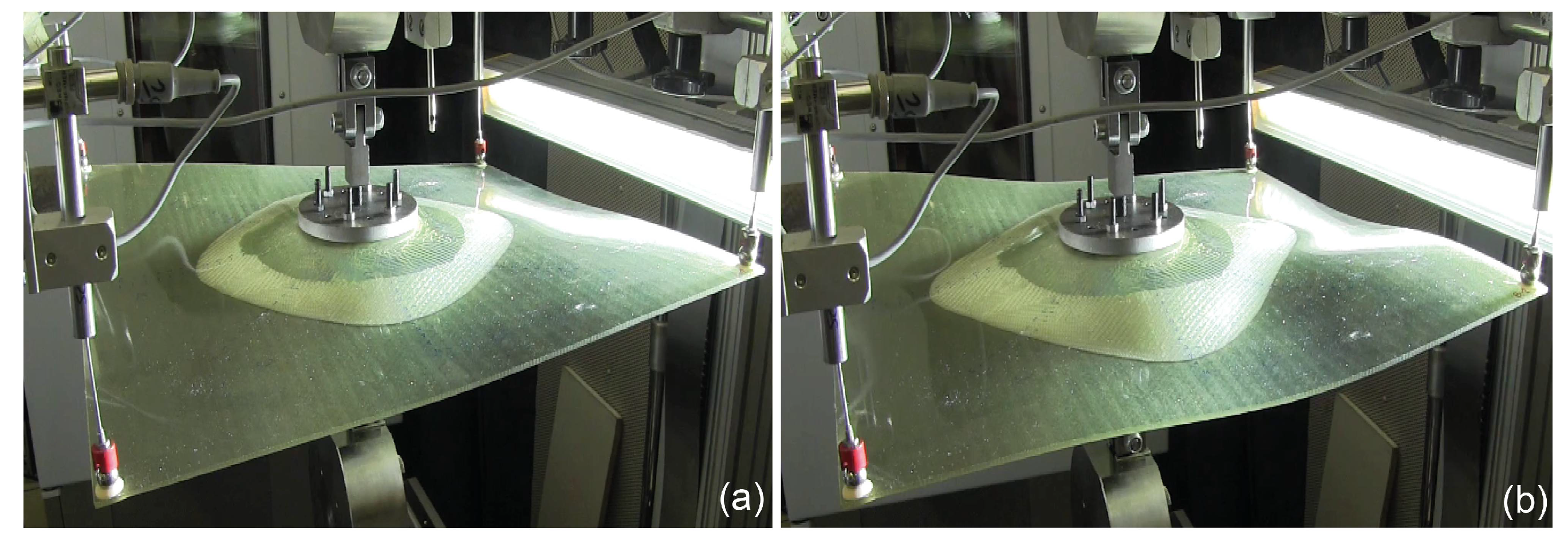
As previously mentioned, the vertical displacements on the four corners were recorded by the LVDTs. Different values were recorded depending on the corner for all the plates except for the CFM pair, where the four corners presented approximately the same displacement values. The variation in stiffness and the different distances from the crack tip to the free end depending on the direction of propagation resulted in the recorded boundary behaviors. Initially, the crack propagations were not affected by these boundary displacements and a symmetric and stable propagation could be observed. When the boundary displacements became higher, they started to influence the crack front and the symmetry in the growth was lost (see Figure 4).
The crack lengths vs. opening displacement response of the W50.50.1 plate is shown in Figure 3a, the blue lines represent the orthogonal directions (i.e., 0/90°) and the magenta lines represent the diagonal directions (i.e., ±45°). The limit of the symmetric behavior corresponded to a 30-mm opening displacement and is marked with a vertical red line. To obtain a continuous evaluation of the crack front, average curves for the orthogonal and diagonal directions were derived by means of parabolic expressions, as shown in Figure 3a. The same representation is shown in Figure 3b for the W60.40.1 plate. Here, the blue lines represent the orthogonal directions with 60% reinforcement, the green lines the orthogonal directions with 40% of reinforcement and the magenta lines the diagonal directions. The corresponding average crack length curves were plotted for the three groups of directions. The limit of symmetric propagation corresponded to a displacement of 26.2 mm. The load and crack lengths vs. the displacement curves of the CFM.1 plate is presented in Figure 3c. Due to the concentric growth of the crack, the values of the crack lengths showed the same trend.
3.2. Crack Propagation Patterns
Crack propagation in the W50.50 plates advanced symmetrically to the orthogonal axes up to around 30 mm of propagation in the diagonal directions and 50 mm of propagation in the orthogonal directions in both plates. The shape of the crack front for the last symmetric contour for W50.50.1 is drawn in blue in Figure 5a. From this point onwards, the boundary displacements started to affect the specimens’ propagation behavior. A similar performance was found for the W60.40 laminates where the crack grew symmetrically to a propagation length of around 45 mm in the orthogonal directions of 60% reinforcement, 15 mm in the orthogonal directions of 40% reinforcement and 20 mm in the diagonal directions. In Figure 5b the shape of the last symmetric crack front for the plate W60.40.1 is also indicated in blue. For the CFM laminates a concentric circular crack front propagation was observed as expected for an in-plane isotropic reinforcement. A propagation along the entire contour of 22.5 mm for CFM.1 was achieved before failing as a result of matrix failure initiating from the holes (Figure 5c). All the cracks propagated in the plane of the pre-cracks, i.e., the midplane.
3.3. Compliance Behavior
The experimental values of the crack lengths along the different directions were used to derive the corresponding average curves (see Figure 3), providing continuous evaluation of the crack propagation fronts. The area of the crack was calculated for each increment as the area between the obtained crack front and the loading line, as for the standard fracture mechanics experiments. The compliance plotted against the crack area is shown only for W50.50.1 plate in Figure 6a) where a initial descending branch down to a minimum and then an ascending branch, corresponding respectively to a stiffening and subsequent softening of the system, can be observed. Similar behavior was detected in the rest of the plates.
4. Discussion
4.1. Increasing Load Behavior
A continuously increasing load-opening displacement behavior was monitored from the beginning of all experiments up to the loss of symmetry of propagation or failure, depending on the plate. In contrast to the results shown in this paper, in standard fracture mechanics experiments, the load always decreases once the crack starts to propagate. This behavior can be understood by comparing how the crack grows in both cases. For standard fracture mechanics experiments the crack area grows proportionally throughout the entire experiment. For the 2D experiments presented here, the crack was embedded in the laminate and consequently, since the crack area started to grow symmetrically, the length of the crack front increased accordingly. As a result, a disproportionate growth of the crack area occurred forcing the load to increase to continue the propagation of the crack.
4.2. Stiffness-Related Mechanisms
Three different mechanisms affecting the specimens’ stiffness could be distinguished in the experiments: stretching, fiber bridging and crack propagation. When thin beams, plates or shells are subjected to transversal efforts and their boundary conditions are fixed on both sides in such a way that their deformation will cause in-plane tension (called stretching), the structure will become significantly stiffer with increasing deformation. For the specimens investigated here, the boundary conditions caused stretching to become a significant stiffening mechanism. As the crack opened, two curvatures appeared: the radial and the circumferential, see Figure 4. As a result of the geometrical constraints, the plates were therefore subjected to a bi-directional stretching phenomenon. Once the crack started propagating, two additional mechanisms were activated, fiber bridging, as an additional stiffening mechanism, and crack propagation itself as a softening mechanism. The fiber bridging was not measured and due to the nature of the experiment it could not be observed either, but it was expected to exist mainly for the CFM specimens and on a much smaller scale for the rest of the specimens. Typically, for a standard fracture experiment, crack propagation is the dominant mechanism after crack initiation, leading to an upwards behavior of the compliance. On the contrary, for these 2D experiments, the stiffening mechanisms played an important role in the performance of the specimens, prevailing over the softening and thus significantly affecting the results.
Based on the curve presented in Figure 6a, an identification of the stiffening and softening regions in both the compliance vs. crack curve (also in Figure 6a) and load vs. displacement curve (Figure 6b) was carried out for the plate W50.50.1. Two regions were differentiated on the compliance vs. crack area curve. The first region, designated “A”, which spans from crack initiation (“initiation point”) up to a minimum (“transition point”), represents the interval where the stiffening mechanisms (stretching and fiber bridging) prevail over the softening mechanisms (crack propagation), causing the corresponding decrease in compliance. Only when the softening becomes the dominant mechanism, prevailing over the others (at the transition point) does the compliance start to grow, then entering the second region, designated “B”. The same differentiation procedure in the compliance vs. crack curve can be established for the W60.40 and CFM plates by identifying the minimum values as from which the general trend of the compliance increases.
5. Conclusions
The 2D delamination behavior of composite laminates with a circular embedded pre-crack under quasi-static out-of-plane loading has been experimentally investigated. The following conclusions were drawn:
- An experimental design suitable for investigating the 2D propagation of an embedded pre-crack under out-of-plane opening loading was successfully developed.
- Increasing loads were obtained as a result of a continuously increasing crack front length and a consequently disproportionate increase in the propagation area.
- As the plates started to deform, stretching stresses appeared as a result of the geometrical constraints. Consequently, the plates were subjected to a stiffening effect.
- Stretching of the specimens and fiber bridging (both stiffening mechanisms) were capable of delaying the general softening of the system that typically occurs once the crack starts to propagate.
Author Contributions
A.C.-M., A.P.V. and T.K. conceived and designed the experiments, analyzed the data and wrote the paper. A.C.-M. performed the experiments.
Acknowledgments
The authors wish to acknowledge the support and funding of this research by the Swiss National Science Foundation (Grant No. 200021_156647/1).
Conflicts of Interest
The authors declare no conflict of interests.
References
- Benzeggagh, M.L.; Kenane, M. Measurement of mixed-mode delamination fracture toughness of unidirectional glass/epoxy composites with mixed-mode bending apparatus. Compos. Sci. Technol. 1996, 56, 439–449. [Google Scholar] [CrossRef]
- ASTM D5528-13: Standard test method for mode I interlaminar fracture toughness for unidirectional fiber-reinforced polymer matrix composites. In Annual Book of ATM Standards: Adhesive Section 15.03; ASTM International: West Conshohocken, PA, USA, 1994.
- Nilsson, K.F.; Thesken, J.C.; Sindelar, P.; Giannakopoulos, A.E.; Storakers, B. A theoretical and experimental investigation of buckling induced delamination growth. J. Mech. Phys. Solids 1993, 41, 749–782. [Google Scholar] [CrossRef]
Figure 1.
(a) GFRP plate configuration; (b) general 3D view of the loading system; (b,c) A’A section view. Dimensions in mm.
Figure 1.
(a) GFRP plate configuration; (b) general 3D view of the loading system; (b,c) A’A section view. Dimensions in mm.

Figure 2.
(a) Experimental set-up; (b) instrumentation layout; (c) layout of crack measuring system.
Figure 2.
(a) Experimental set-up; (b) instrumentation layout; (c) layout of crack measuring system.

Figure 3.
Load and crack lengths vs. opening displacement curves of plates (a) W50.50.1; (b) W60.40.1 and (c) CFM.1.
Figure 3.
Load and crack lengths vs. opening displacement curves of plates (a) W50.50.1; (b) W60.40.1 and (c) CFM.1.

Figure 4.
Example of deformation in plate W50.50.1 at (a) limit of symmetric propagation and (b) beyond limit.
Figure 4.
Example of deformation in plate W50.50.1 at (a) limit of symmetric propagation and (b) beyond limit.

Figure 5.
Crack propagation pattern for (a) W50.50.1; (b) W.60.40.1; and (c) CFM.1.

Figure 6.
Stiffening and softening regions on W50.50.1; (a) compliance vs. crack area; (b) load vs. displacement.
Figure 6.
Stiffening and softening regions on W50.50.1; (a) compliance vs. crack area; (b) load vs. displacement.


Table 1.
Description of GFRP plates.
| Plate Type | No. of Layers | Dimensions (mm, Width × Height × avg. Thickness) |
|---|---|---|
| W50.50.1/W50.50.2 | 8 | 460 × 460 × 3.33/480 × 480 × 3.53 |
| W60.40.1/W60.40.2 | 6 | 410 × 410 × 3.05/410 × 410 × 3.06 |
| CFM.1/CFM.2 | 6 | 420 × 420 × 7.5/420 × 420 × 6.99 |
Publisher’s Note: MDPI stays neutral with regard to jurisdictional claims in published maps and institutional affiliations. |
© 2018 by the authors. Licensee MDPI, Basel, Switzerland. This article is an open access article distributed under the terms and conditions of the Creative Commons Attribution (CC BY) license (https://creativecommons.org/licenses/by/4.0/).
Share and Cite
MDPI and ACS Style
Cameselle-Molares, A.; P. Vassilopoulos, A.; Keller, T. Novel Experimental Design for Two-Dimensional Delamination in Fiber-Reinforced Polymer Laminates. Proceedings 2018, 2, 408. https://doi.org/10.3390/ICEM18-05283
AMA Style
Cameselle-Molares A, P. Vassilopoulos A, Keller T. Novel Experimental Design for Two-Dimensional Delamination in Fiber-Reinforced Polymer Laminates. Proceedings. 2018; 2(8):408. https://doi.org/10.3390/ICEM18-05283
Chicago/Turabian StyleCameselle-Molares, Aida, Anastasios P. Vassilopoulos, and Thomas Keller. 2018. "Novel Experimental Design for Two-Dimensional Delamination in Fiber-Reinforced Polymer Laminates" Proceedings 2, no. 8: 408. https://doi.org/10.3390/ICEM18-05283