1. Introduction
In post-stroke patients, impaired cerebral cortex function limits coordinated movement and typically manifests by pronounced asymmetric deficits [
1]. The restoration of symmetric gait is a major goal of post-stroke rehabilitation, to allow independent walking and living [
2]. Current stroke patient rehabilitation assessments, whether in a clinic or at home, involve subjective, task orientated assessments. Whilst these are useful, visual observation alone cannot sufficiently characterise subtle changes to gait [
3]. This is an important consideration as the progress of patient rehabilitation will inform the direction and continuation of physical therapy interventions, particularly if those interventions are home-based. Traditional, marker-based motion capture systems can be prohibitive to healthcare applications from cost, space, time and user-expertise perspectives. In particular, the portability of motion capture systems is a fundamental consideration for practitioners conducting off-site assessments, where a patient’s functional mobility is assessed in their own home. Movement analysis technologies for healthcare applications should therefore aim to be low-cost, portable, simple-to-use and suitable for use in small spaces (e.g., a patient’s home). An objective tool, capable of measuring sensitive gait parameters (e.g., knee joint angle, gait symmetry, etc.), would support home-based assessments of post-stroke gait.
Depth-cameras represent a low-cost alternative to traditional motion capture as calibrated, three-dimensional measurements are captured automatically by a single-camera device (e.g.,
Figure 1b). The Microsoft Xbox 360 Kinect and Xbox One Kinect are low-cost depth-camera devices, originally developed for use in the home. Both the Xbox 360 and Xbox One Kinect provide a software development kit (SDK) for automated 3D human-pose estimation [
4]. Automatic human-pose estimation using Microsoft’s SDK has been assessed in many sport and health applications, including functional movement assessment [
5] and gait analysis [
6]. Whilst automatic human-pose estimation is an extremely useful tool for movement-based analyses, measurement agreement has limited its use as a surrogate motion capture system [
5]. Moreover, whilst joint position estimates contain error [
4], the model-based nature of estimation can exacerbate errors for persons deviating from this model (i.e., stature, shape, etc.).
Marker-tracking methods, based on infrared disparity-mapping depth cameras (e.g., Xbox 360 Kinect), have demonstrated promising results [
7]. Macpherson and colleagues [
7] used an Xbox 360 Kinect to process three-dimensional point cloud data based on four retro-reflective markers, mounted to participant’s posterior pelvic region. When compared to three-dimensional motion capture, Macpherson and colleagues [
7] reported 95% limits of agreement as ≤9.9 mm and ≤4.6° for linear and angular motions of the pelvis and trunk during treadmill-based walking and running. Whilst reasonable agreement was demonstrated, limitations associated with processing three-dimensional point cloud data were highlighted as a necessary area of development to improve measurement accuracy.
The advent of infrared time-of-flight depth-cameras (e.g., Xbox One Kinect), which provide higher resolution sensors with increased depth measurement fidelity [
8], might yield improved accuracy, addressing previous limitations [
7]. Therefore, the use of infrared time-of-flight depth cameras might expand potential applications of depth-cameras for healthcare specialists. Recently, bespoke analysis software, capable of automatic and real-time, three-dimensional position measurement using an infrared time-of-flight depth-camera, has been developed. The aim of this study was to demonstrate a low-cost, portable and simple-to-use system for the measurement of basic gait parameters.
2. Materials and Methods
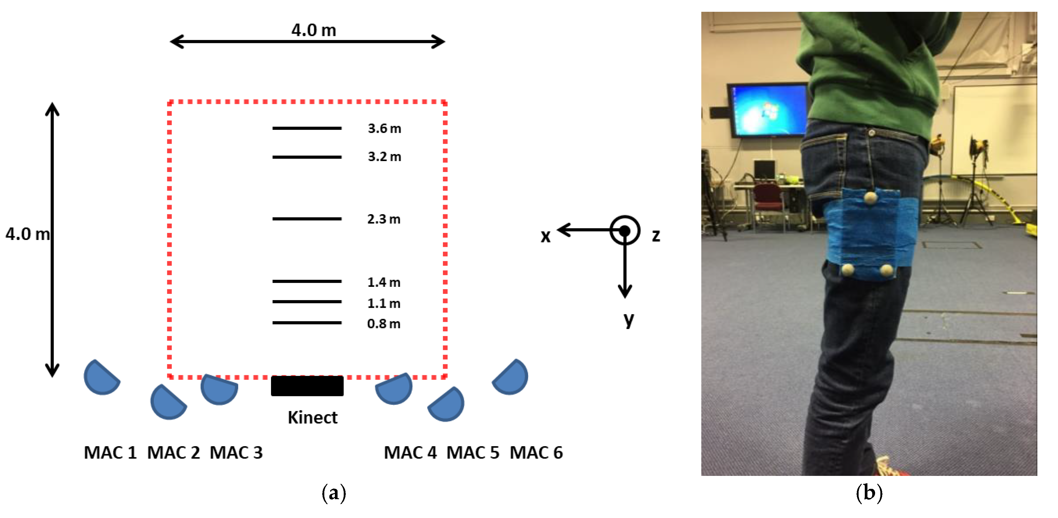
All procedures were approved by the Research Ethics Committee of the Faculty of Health and Wellbeing, Sheffield Hallam University. A single female participant (age = 24 years; stature = 1.68 m; mass = 53 kg) was recruited and written informed consent was obtained. A retro-reflective marker-triad was secured to the lateral aspect of the participant’s right thigh (e.g.,
Figure 2b).
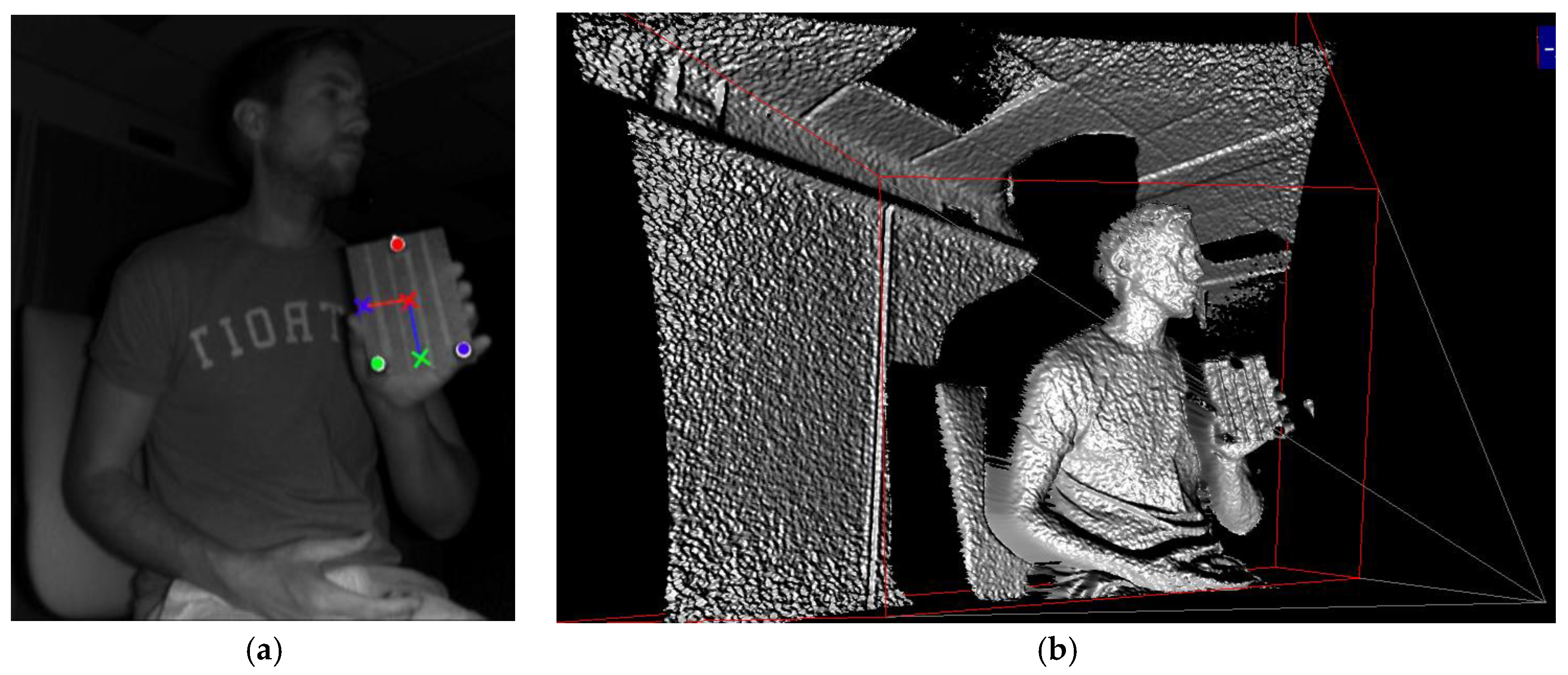
Bespoke analysis software, developed using the .NET (C#) framework, automatically measured the three-dimensional position and orientation of the marker triad in real-time. Infrared images captured (~30 Hz) by an Xbox One Kinect (Microsoft, Redmond, USA) are first converted to logical images (based on a threshold), allowing retro-reflective markers to be tracked (e.g.,
Figure 1a). Depth data—based on the phase-shift distance of modulated infrared light [
8]—cannot be derived from marker locations directly as retro-reflective material scatter infrared light. Therefore, image locations of retro-reflective markers (e.g.,
Figure 1a) are used to track three coplanar image targets (e.g., red, green and blue tracking crosshairs highlighted by ‘L’ shape in
Figure 1a) within infrared images. The three-dimensional, camera space coordinates of coplanar targets are then extracted and a marker-triad transformation matrix (comprising a rotation matrix and translation vector) calculated for each received frame. For the purpose of assessment, thigh angle, defined as the vertical axis of the marker triad (e.g., blue vector superimposed on
Figure 1a) was calculated.
The participant was asked to walk at a self-selected pace (perpendicular to the depth-camera) from a stationary start, at three close-range (0.8, 1.1 and 1.4 m) and three long-range (2.3, 3.2 and 3.6 m) camera-distances (e.g.,
Figure 2a). Three trials at each camera-distance were recorded. A six-camera motion capture system (Motion Analysis Corporation, Santa Rosa, CA, USA) was used to concurrently record the three-dimensional position of retro-reflective markers at 150 Hz. Immediately prior to walking trials, the participant was asked to perform a small vertical jump, to allow the temporal alignment of kinematic data derived by both measurement systems. All position data were reported in the laboratory coordinate system (e.g.,
Figure 2a). Depth-camera data were resampled to 150 Hz using linear interpolation and smoothed using a discretised smoothing spline, based on generalised cross-validation [
9]. Thigh angle was reported with respect to the global vertical axis. Agreement was assessed using Bland-Altman 95% limits of agreement (LOA). In the case of heteroscedastic data distribution (i.e., |r
2| > 0.1), ratio LOA (dimensionless) was also reported. Further, root-mean square error (RMSE) was assessed using the following:
where
XiR is the criterion,
Xir is the estimate and
N is the number of data points.
3. Results
For close-range camera-distances, 95% of depth-camera thigh angle estimates were between ±4.9°. Further, RMSE for thigh angle estimates was <2.5° for close-range camera distances
. Thigh angle differences for 0.8 and 1.1 m camera-distances were heteroscedastic; 95% of ratios were between 34.6 and 23.8% of the mean ratio respectively (
Table 1).
For long-range camera distances, 95% of depth-camera thigh angle estimates were between ± 9.5°. Further, RMSE for thigh angle estimates was <6.7°
. Thigh angle differences for 2.3 and 3.2 m camera distances were heteroscedastic; 95% of ratios were between 54.2 and 60.4% of the mean ratio respectively (
Table 1).
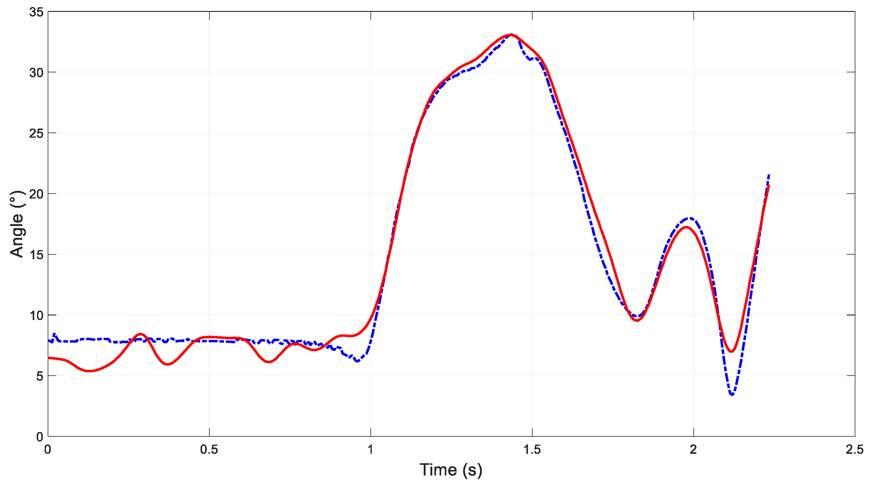
Figure 3 presents thigh angle (wrt. global vertical axis) time histories for a stand-to-walk trial, measured using Xbox One Kinect and bespoke software (solid red line) and motion capture (dashed blue line).
4. Discussion
The purpose of this study was to demonstrate a low-cost, portable and simple-to-use system for the measurement of basic gait parameters. Using an Xbox One Kinect and bespoke software, thigh angle (wrt. global vertical axis) for a participant walking at a self-selected pace, was automatically captured and analysed in real-time. For long-range camera distances (i.e., 2 m < camera distance < 4 m), systematic thigh angle differences increased with camera distance. This reflects known depth-accuracy limits of depth-cameras [
8] as well as decreasing resolution of tracking targets (i.e., markers). However, close-range measurement errors were not related to camera distance; rather, an optimal camera-distance emerged (
Table 1). Using a camera-distance of 1.1 m, systematic thigh angle differences were <0.1° and 95% of differences between ± 2.65°. Furthermore, thigh angle RMSE was 1.35°. However, thigh angle differences at a camera distance of 1.1 m did exhibit heteroscedasticity. This potentially highlights a limitation of a relatively low but also variable sample rate (e.g., ~30 Hz). For example,
Figure 3 indicates that thigh angle was overestimated at ~2.1 s. It is reasonable to assume that thigh angle magnitude at this instant (indicated by the criterion) was not beyond the system’s measurement range. This therefore might indicate sample rate as a potential contributor to thigh angle overestimation in this case.
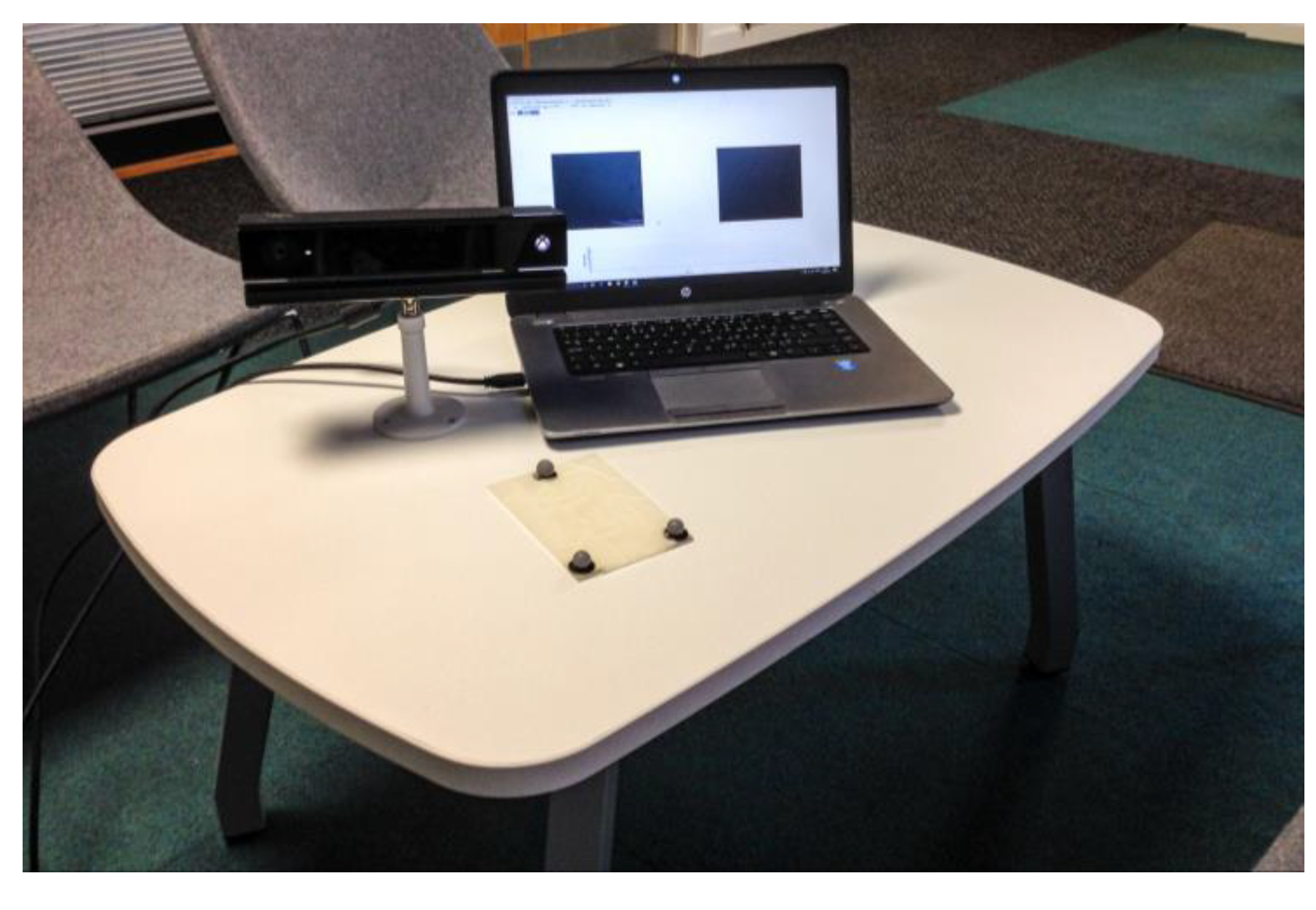
Potential clinical applications of a portable, close-range, three-dimensional measurement system might include home-based assessments of gait.
Figure 4 illustrates equipment used in the current study. Clinicians have highlighted that such a tool would help supplement their assessment of stroke survivors’ walking gait and provision of rehabilitative care. However, whilst three-dimensional measurements are derived by the current system, thigh angle—a predominantly sagittal plane motion—was assessed as a demonstra. The calculation of more complex kinematic measures, such as functionally defined joint angles, would aid clinician’s assessment of patients. Future development should therefore consider functional joint angle definitions as well as potential effects of multi-planar triad rotations.


