1. Introduction
Following the release of a World Economic Forum report in January 2011 [
1], the Water, Energy and Food (WEF) Nexus has gained increasing attention globally among researchers and policy makers as the interlinkage between the water, energy and food supply systems is the major focus in countries’ sustainable development strategies. The WEF Nexus consists of integrated management paradigms [
2,
3,
4,
5,
6,
7], dealing with issues such as rapid economic growth, expanding populations and limited cultivated lands. Water scarcity in many parts of the world [
8,
9,
10] triggered a significant interest toward agricultural [
11] and drinking water issues [
12]. Since WEF Nexus also addresses opportunities to increase resources supplies, we revisited, as a possible low-cost alternative, the use of the hydraulic ram.
A hydraulic ram [
13,
14,
15] is a cyclic water pump powered by hydropower. It is a device that exploits the potential energy of a liquid mass to lift up a portion of it at an altitude higher than the source. Known also as hydram, it does not require other form of external energies to work. Its functioning persists continuously and automatically as long as there is water availability. Basically, it is based on the physical principle of the water hammer effect [
16,
17], consisting in the development of pressure waves as consequence of abrupt transients, triggered by the rapid valve opening or closing.
Invented over 200 years ago, it soon became popular in the 1800’s and early 1900’s, then considered obsolete with the general availability of electricity. Recently, the interest toward this device is renewed due its practical installation in remote areas of developing regions, e.g. Tanzania, Kenya and Zambia [
18]. Since 1980’s research contributions have been proposed to optimizing its efficiency through a number of modifications [
19,
20,
21]. This device could then be exploited for the supply of fresh water in some areas of the world allowing the use of land for food. In this context, an important factor demanding focus and improvement is the operating efficiency of the hydram, see e.g., [
22,
23] about recent investigations on hydraulic ram parameter optimization.
The aim of the present investigation was to assess the behaviour of a hydraulic ram assembled at the Laboratory of Environmental and Maritime Hydraulics (LIDAM) of the Department of Civil Engineering (DICIV), University of Salerno, Italy, through the acquisition and processing of pressure signals, detected in time with transducers. The initial phase, corresponding to the apparatus characterization, was then carried out shedding lights on the behaviour of each component, as well as the interaction among them. Difficulties related to the calibration of data acquisition devices were solved by substituting the built-in 220 V/5 V transformer of the adopted data acquisition hardware with a 6 V independent battery pack supply, in order to obtain signals reliable.
2. Materials and Methods
To examine the effects of the pressure propagation induced by the water hammer, a series of experiments were conducted in which pressure data were sampled in time as function of the valves position. The
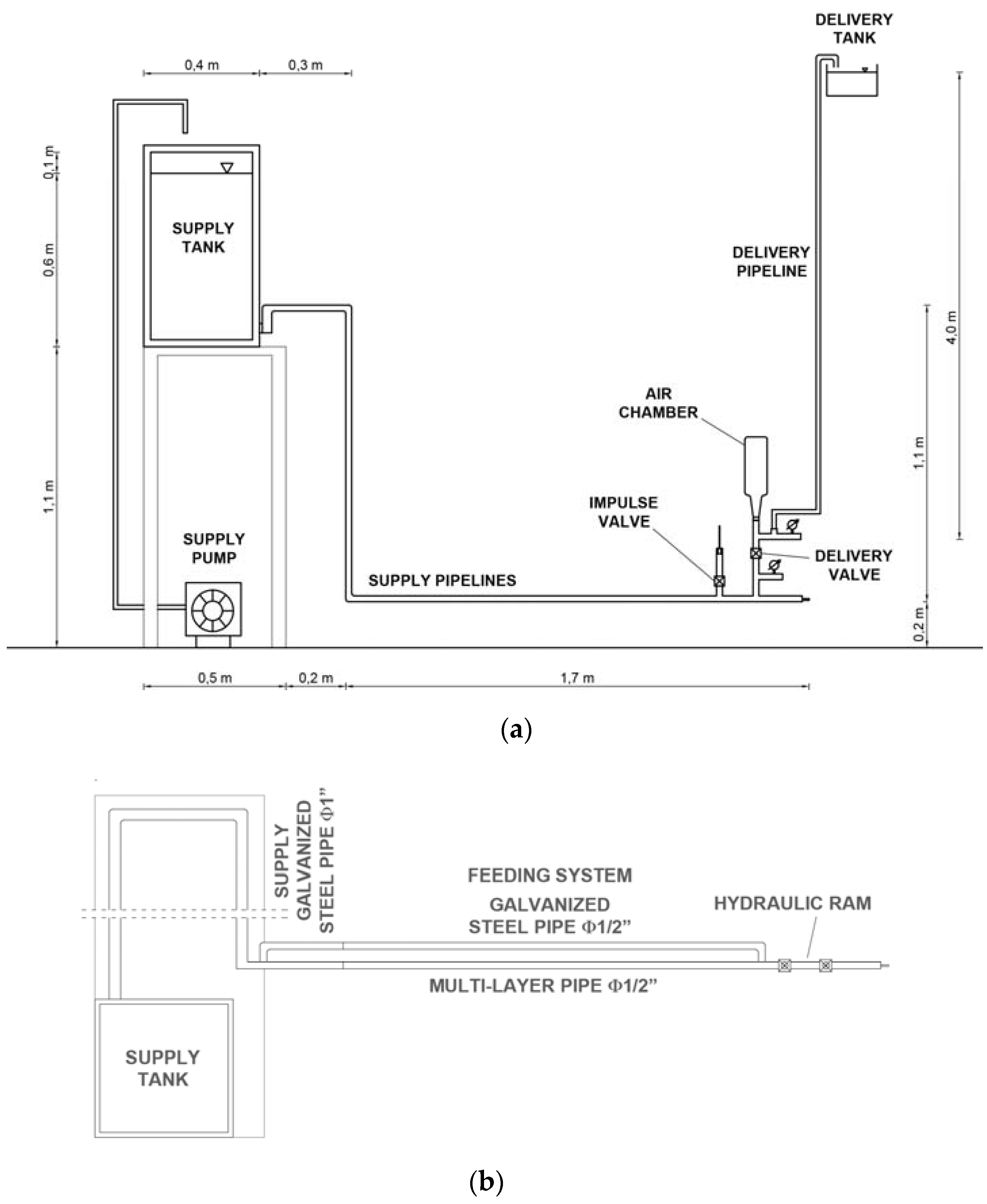
Figure 1 sketches the adopted apparatus @ LIDAM. It is assembled with a centrifugal pump, model Lowara CEA70/5/A (flow rate range: 30–80 L/min, hydraulic head range: 28.8–20.2 m) which serve the supply tank of 100 L of capacity. The pump is provided with an inverter which allows the regulation of the flow rate at the tank with the aim of reaching steady state conditions over a time window of some cyclic periods. A hydraulic ram is then fed by gravity conveying water to a higher level.
The supply or drive pipes composing the feeding system (
Figure 1b) consist of two lines of different material, a first one of galvanized steel with nominal diameter DN
gs = 12.7 mm (½ inches), thickness t
gs = 1.3 mm and length L
gs = 3.00 m, the second one of multi-layer with nominal diameter DN
ml = 12.7 mm (½ inches), thickness t
gs = 1.0 mm and length L
ml = 2.40 m. They can operate simultaneously or one at time. In the following, only the galvanized steel pipe is taken into account.
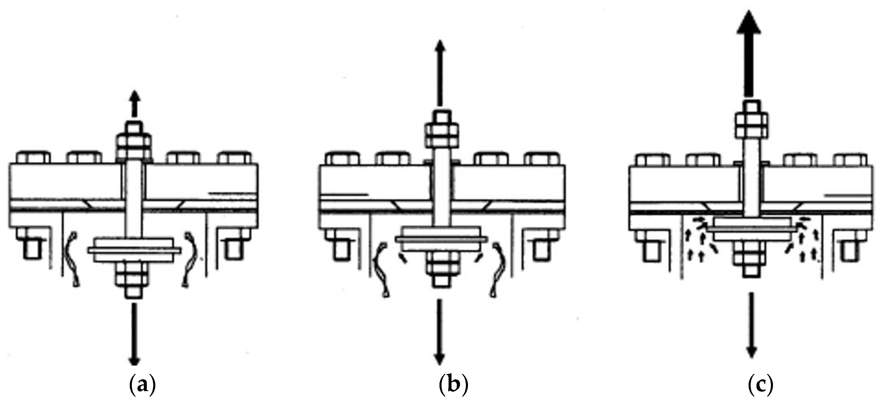
At the beginning of each cycle, the water coming from the tank reaches the impulse or clack valve (
Figure 2) which is initially open (i.e., in the lower position, see
Figure 2a) because of its weight, and the delivery valve is closed because of the overlying water column. At this stage, some water is released outside resembling a gush, this is the reason why it is also known as waste valve. Under the effect of the gravity, the water flowing in the drive pipe increase its own speed. When the hydrodynamic pressure force acting on the lower side of the impulse valve’s wins its weight, the valve starts lifting up at increasing speed (
Figure 2b) and finally closes (
Figure 2c), yielding a quick increase of pressure (onset of the water hammer).
The generated positive overpressure now acts against the delivery valve, opening it and inducing a flow of water into the air chamber which in turns push water into delivery pipe up to a delivery tank located to a level higher that feeding tank. The air chamber prevents the occurrence of shock pressure waves in the delivery pipe as well as improves the overall pumping efficiency by allowing a more constant flow at the delivery tank. Then the momentum of the water flowing into the drive pipe decreases to the point the flow reverses, closing the delivery valve.
Meanwhile a reflected negative pressure wave, generated at the supply tank when the previous positive impacts at its base, travels over the drive pipe causing the lowering of piston, allowing the process to start again.
In order to detect the involved rapid pressure variation, high sampling speed pressure transducers and sampling modules up to 1 kHz were employed. The adopted system of acquisition comprises the following devices:
two hydraulic pressure transmitters, model Trafag NAH 8253®, pressure range 0–2.5 bar (overpressure 5 bar), pressure accuracy 0.15%, sampling rate: 1 kHz. Of Wheatstone bridge type, they relate the induced deformation a membrane undergoes to a potential difference proportional to the exerted pressure.
Two shielded electrical plugs m12x1, 5-pole, for the electrical connection of the transducers.
A data acquisition (DAQ) hardware comprehending the National Instruments (NI) cDAQ-9174® hub, hosting the sampling modules NI 9218® and NI 9220®.
A digital camera, model AOS AOS Q-PRI with a sampling rate of 1 kHz, provided with a 3mp sensor.
3. Results
The results, in the following presented, highlighted that the transient generated by the hydraulic ram apparatus depends on the propagation celerity of the generated pressure waves. Before each acquisition, two calibration points of sensors were set for the subsequent pressure detecting. The first one in absence of water in the system to check the zero reference level, the second in the presence of a liquid static load.
3.1. Measure of the Propagation Celerity
Water hammer generating pressure waves, exhibits a propagation celerity “a” [m/s] depending on the pipe material, elasticity and liquid compressibility, as expressed by the following general equation
where ρ and ε are the water density and the water compressibility modulus respectively, s and D are the thickness and inner diameter’s pipe respectively, E the pipe Young’s modulus.
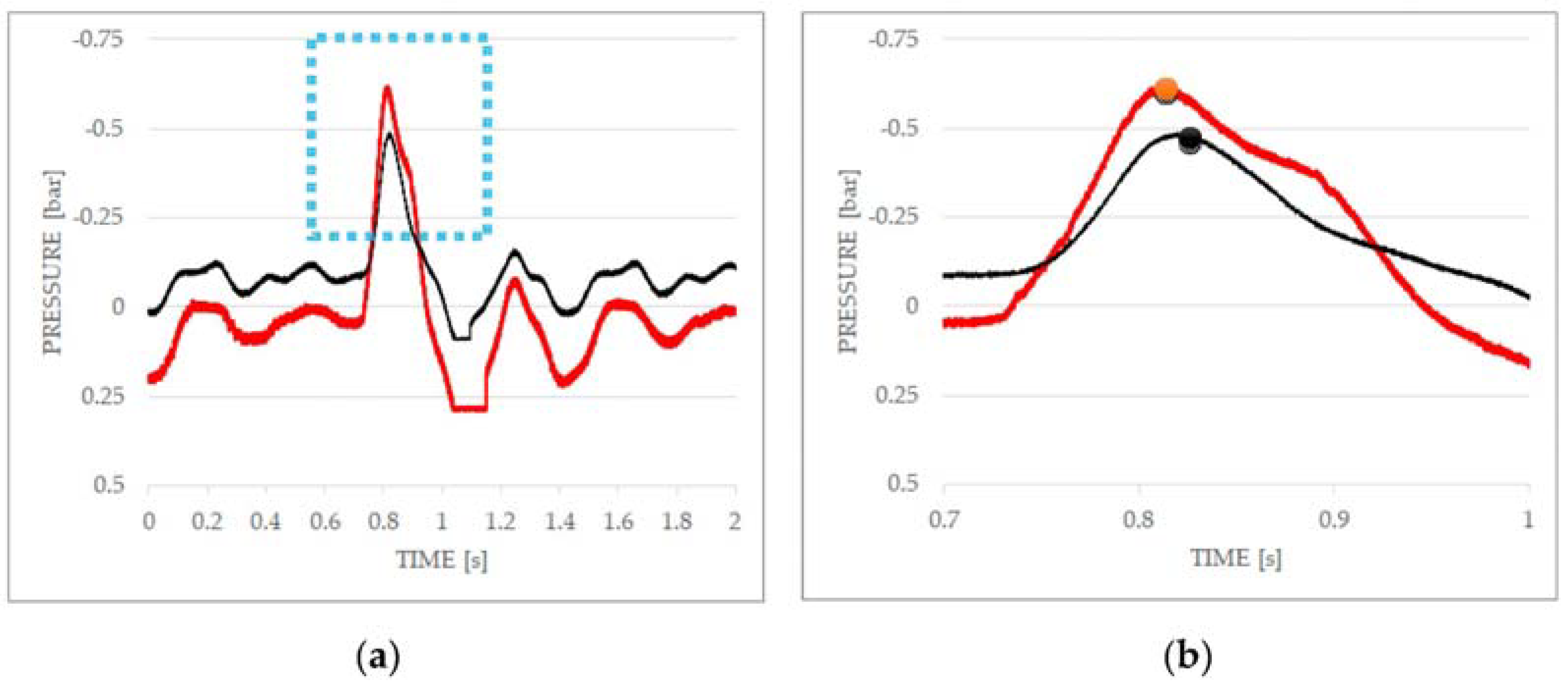
In order to detect the propagating celerity of the developed pressure waves, two transducers Trafag NAH 8253
® were placed on the Supply galvanized steel pipe, 7.30 m long, nominal diameter DN 1” (25.4 mm). The following
Figure 3a shows the pressure evolution trend for transducer #1 (red line) and #2 (black line). As can be noted by magnifying around the main pressure peaks (
Figure 3b), a pressure dumping occurs when the pressure wave travels from the transducer #1 to transducer #2.
From the application of Equation (1) follows a propagation celerity a = 308 m/s.
3.2. Measure of the Impulse Valve Flow Coefficient
The flow coefficient of a valve, commonly indicated as K
v, is a parameter related to the hydraulic resistance experienced by the crossing flow, i.e., the ease for the fluid flow to pass through the device. It relates the volumetric outflow discharge Q to the concentrated head loss Δp induced by the valve closure, as follows
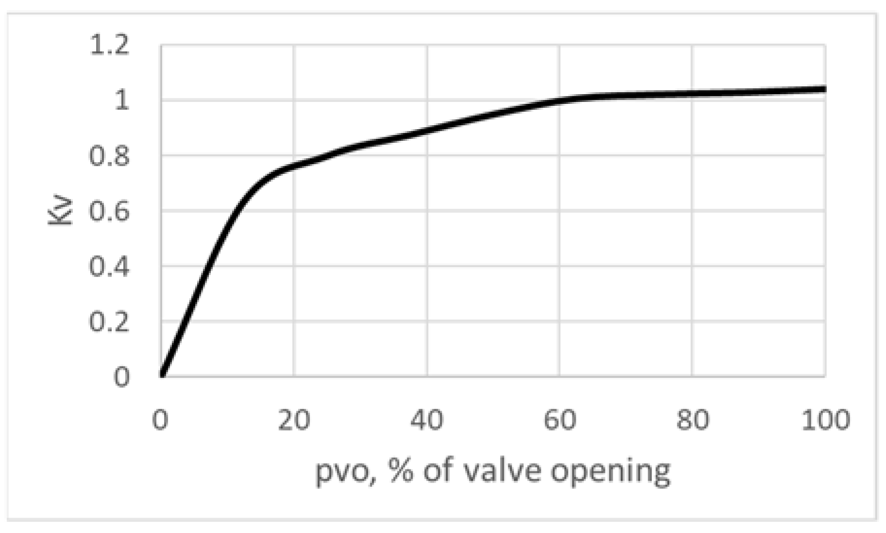
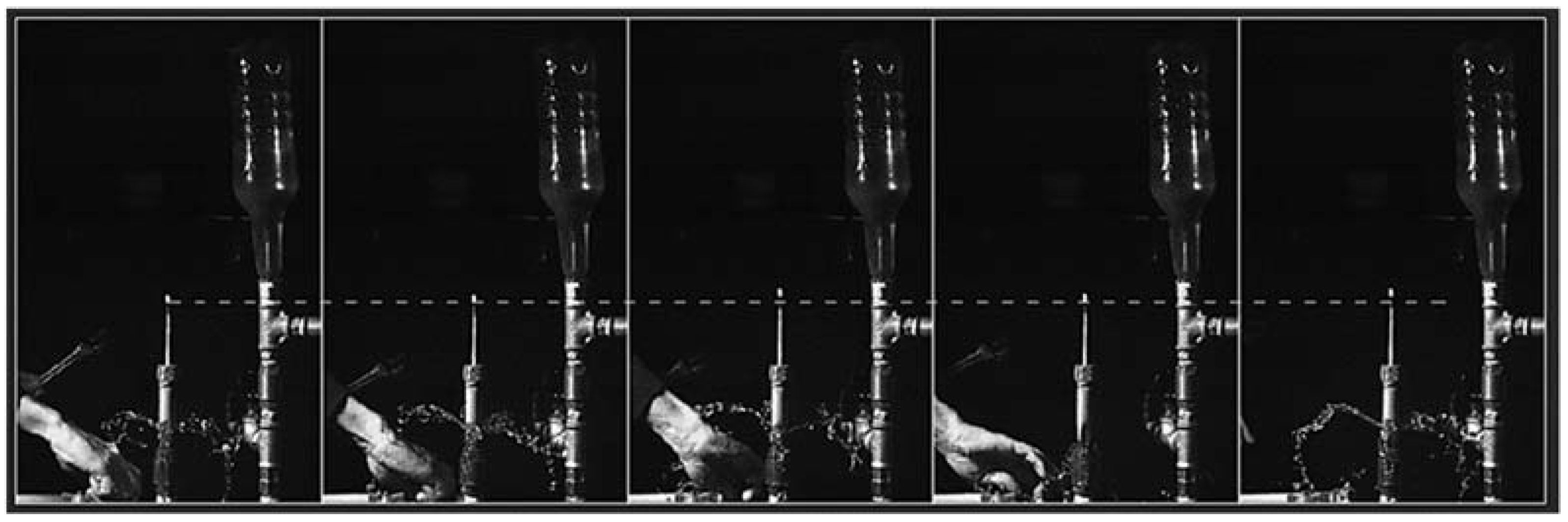
In
Figure 4 it is shown the relationship between K
v and the percentage of valve opening, obtained experimentally by detecting the position of the piston in time, processing the video recordings, see the reference level depicted by the dashed white line in
Figure 5.
As can be noted, Kv does not vary significantly when the opening percentage pvo is in the range 20–100%. Most of its effect is produced when it is about to close (pvo in the range 0–20%), where correspondingly Kv varies of about 80%.
3.3. Generating Pressure Waves and Valves Location in Time
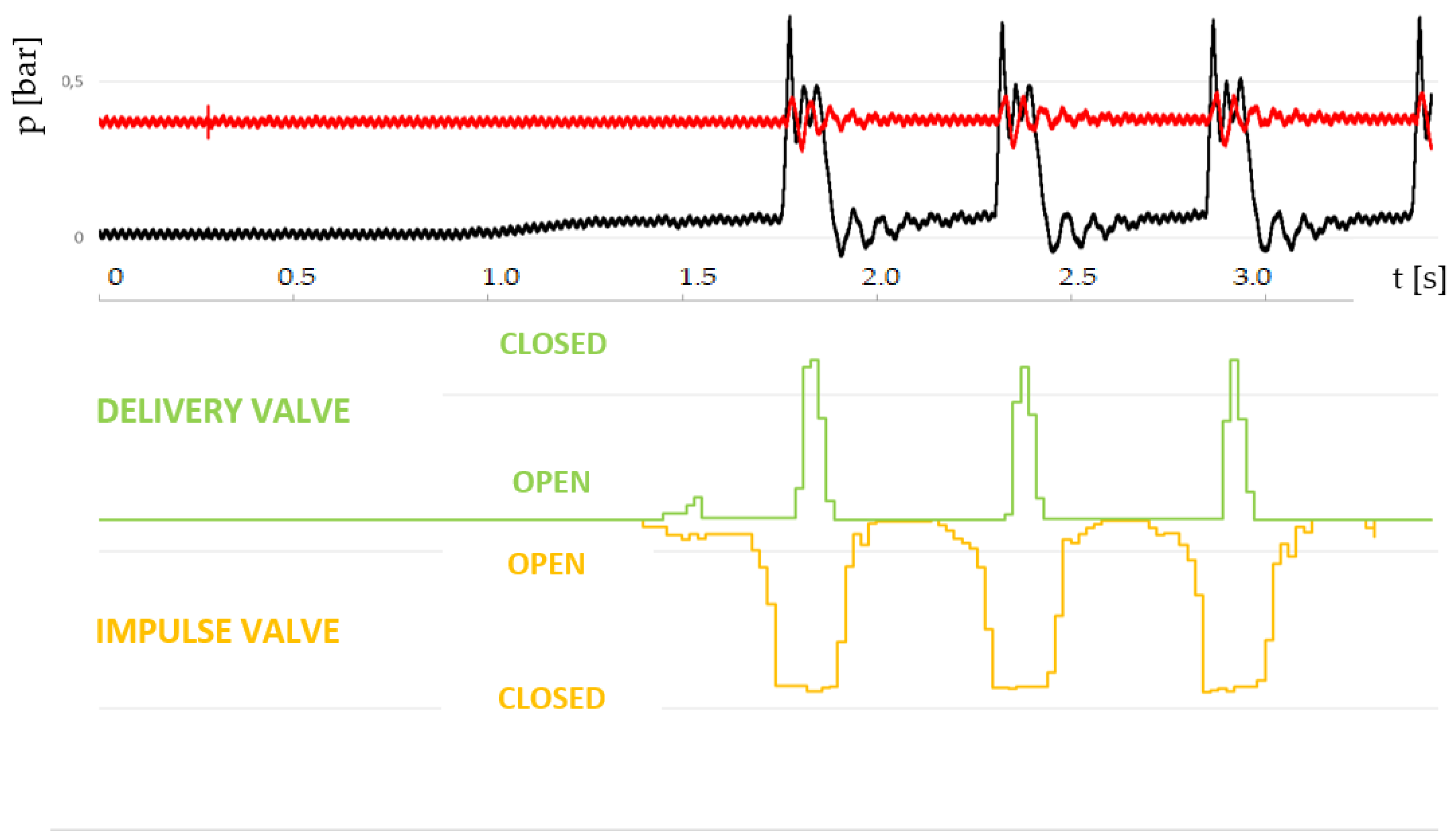
The evolution of the pressure waves induced by the hydraulic ram was detected, then related to the temporal location of impulse and delivery valve’s pistons (See
Figure 5).
This time, the pressure transducers were located immediately before the impulse valve and immediately after the delivery valve. When the hydraulic ram operates, the piston’s valves were video recorded and pressure at the transducers detected. Their correlation is sketched in
Figure 6.
The pressure trend at the impulse valve (black line in
Figure 6) is in good agreement with the theoretical model proposed by Krol [
24]. Initially, the impulse valve is open, acceleration of water takes place inside the drive pipe to the point the hydrodynamic force exerted on the impulse valve starts closing it. Once the complete closure at the impulse valve occurs a pressure peak is generated. The overpressure, once at the delivery valve, forces it to open it and serving the delivery pipe. The related duration t
dvo (delivery valve opened) during which the discharge takes place is very short of the order
in accordance with the model of Krol.
4. Conclusions
A preliminary investigation was carried on a hydraulic ram pump assembled at the Laboratory of Environmental and Maritime Hydraulics, University of Salerno, Italy. Unsteady pressure profiles at the impulse and delivery valve were detected by means of pressure transducers. The propagating celerity of the developed pressure waves was derived. Impulse and delivery valve displacements were detected by means of video recordings, showing a good agreement with the theoretical model proposed by Krol [
24]. Impulse valve flow coefficient was derived by processing video images showing that most of its effect is produced when it is almost closed.
Author Contributions
The tasks of conceiving the experimental apparatus, analyzing data, drawing conclusions and writing the paper were uniformly shared among the authors.
Acknowledgments
The authors wish to express their gratitude to Vittorio Bovolin for supporting this study, Andrea Gattone of National Instruments for the support provided on the calibration of the input signals from pressure transducers and Enrico Bello for his suggestions about the cabling network.
Conflicts of Interest
The authors declare no conflict of interest.
References
- Waughray, D. Water Security: The Water-Food-Energy-Climate Nexus. The World Economic Forum Water Initiative; Island Press: Washington, DC, USA, 2011; ISBN 13 978-1597267366. [Google Scholar]
- Uen, T.-S.; Chang, F.-J.; Zhou, Y.; Tsai, W.-P. Exploring synergistic benefits of Water-Food-Energy Nexus through multi-objective reservoir optimization schemes. Sci. Total Environ. 2018, 633, 341–351. [Google Scholar] [CrossRef] [PubMed]
- Wichelns, D. The water-energy-food nexus: is the increasing attention warranted, from either a research or policy perspective? Environ. Sci. Policy 2017, 69, 113–123. [Google Scholar] [CrossRef]
- Scanlon, B.R.; Ruddell, B.L.; Reed, P.M.; Hook, R.I.; Zheng, C.; Tidwell, V.C.; Siebert, S. The food-energy-water nexus: Transforming science for society. Water Resour. Res. 2017, 53, 3550–3556. [Google Scholar] [CrossRef]
- Lee, M.; Keller, A.A.; Chiang, P.-C.; Den, W.; Wang, H.; Hou, C.-H.; Wang, X.; Yan, J. Water-energy nexus for urban water systems: A comparative review on energy intensity and environmental impacts in relation to global water risks. Appl. Energy 2017, 205, 589–601. [Google Scholar] [CrossRef]
- Al-Saidi, M.; Elagib, N.A. Towards understanding the integrative approach of the water, energy and food nexus. Sci. Total Environ. 2017, 574, 1131–1139. [Google Scholar] [CrossRef]
- Endo, A.; Tsurita, I.; Burnett, K.; Oencio, P.M. A review of the current state of research on the water, energy, and food nexus. J. Hydrol. Reg. Stud. 2017, 11, 20–30. [Google Scholar] [CrossRef]
- Ololade, O.O. Understanding the nexus between energy and water: A basis for human survival in South Africa. Dev. S. Afr. 2018, in press. [Google Scholar] [CrossRef]
- Siddiqi, A.; Diaz Anadon, L. The water–energy nexus in Middle East and North Africa. Energy Policy 2011, 39, 4529–4540. [Google Scholar] [CrossRef]
- Karatayev, M.; Rivotti, P.; Sobral Mourão, Z.; Konadu, D.D.; Shah, N.; Clarke, M. The water-energy-food nexus in Kazakhstan: Challenges and opportunities. Energy Procedia 2017, 105, 3966–3971. [Google Scholar] [CrossRef]
- Ahmad, A.; Khan, S. Water and Energy Scarcity for Agriculture: Is Irrigation Modernization the Answer? Irrig. Drain. 2016, 66, 34–44. [Google Scholar] [CrossRef]
- Spang, E.S.; Loge, F.J. A High-Resolution Approach to Mapping Energy Flows through Water Infra structure Systems. J. Ind. Ecol. 2015, 19, 656–665. [Google Scholar] [CrossRef]
- Brunacci, V. Trattato Dello Ariete Idraulico; Stamperia Reale: Milan, Italy, UK, 1810. [Google Scholar]
- Clark, J. Hydraulic Rams Their Principles and Construction; Batsford: London, UK, 1900. [Google Scholar]
- Gibson, A.H. Water Hammer in Hydraulic Pipelines; Archibald Constable: London, UK, 1908. [Google Scholar]
- Ghidaoui, M.S.; Zhao, M.; McInnis, D.; Axworthy, D. A Review of Water Hammer Theory and Practice. Appl. Mech. Rev. 2005, 58, 49–76. [Google Scholar] [CrossRef]
- Pugliese Carratelli, E.; Viccione, G.; Bovolin, V. Free surface flow impact on a vertical wall: A numerical assessment. Theor. Comput. Fluid Dyn. 2016, 30, 403–414. [Google Scholar] [CrossRef]
- Manuscript Report IDRC-MR102eR 1986. Proceedings of a Workshop on Hydraulic Ram Pump (Hydram) Technology, Arusha, Tanzania, 29 May–1 June 1984. Available online: https://idl-bnc-idrc.dspacedirect.org/bitstream/handle/10625/6625/IDL-6625.pdf (accessed on 20 December 2017).
- Starmer, C. Blake’s Hydram or the rise and fall of the hydraulic ram. Chart. Mech. Eng. 1981, 28, 19–21. [Google Scholar]
- Young, B.W. Generic design of ram pumps. J. Power Energy 1998, 212, 117–124. [Google Scholar] [CrossRef]
- Hussin, N.S.M.; Gamil, S.A.; Amin, N.A.M.; Safar, M.J.A.; Majid, M.S.A.; Kazim, M.N.F.M.; Nasir, N.F.M. Design and analysis of hydraulic ram water pumping system. In Proceedings of the International Conference on Applications and Design in Mechanical Engineering (ICADME 2017), Penang, Malaysia, 21–22 August 2017. [Google Scholar]
- Sarma, D.; Das, M.; Brahma, B. Investigation and Parameter Optimization of a Hydraulic Ram Pump Using Taguchi Method. J. Inst. Eng. Ser. C 2016, 97, 551–559. [Google Scholar] [CrossRef]
- Nambiar, P.; Shetty, A.; Thatte, A.; Lonkar, S.; Jokhi, V. Hydraulic ram pump: Maximizing efficiency. In Proceedings of the International Conference on Technologies for Sustainable Development (ICTSD 2015), Don Bosco Institute of Technology (DBIT), Mumbai, India, 4–6 February 2015; Mande, S., Tripathy, A., Sarangi, R.K., Eds.; ISBN 978-1-4799-8187-8. [Google Scholar]
- Krol, J. The automatic hydraulic ram. Proc. Inst. Mech. Eng. 1951, 165, 53–65. [Google Scholar] [CrossRef]
| Publisher’s Note: MDPI stays neutral with regard to jurisdictional claims in published maps and institutional affiliations. |
© 2018 by the authors. Licensee MDPI, Basel, Switzerland. This article is an open access article distributed under the terms and conditions of the Creative Commons Attribution (CC BY) license (https://creativecommons.org/licenses/by/4.0/).


