1. Introduction
In both developing and developed countries, the need for clean and sustainable energy sources is growing more and more stringently in order to contrast the anthropic climate changes.
In Small Hydropower Plants (SHPs), Pumps as Turbines (PaTs) could be an important renewable energy technology, contributing to rural electrification, sustainable industrial development as well as the reduction of greenhouse gas emissions and deforestation [
1].
Due to the complexity of developing new micro-turbines for SHPs, the use of pumps operating in reverse mode could represent a practical solution, in consideration of the wide range of pumps in terms of specific speed numbers and available standard sizes. PaTs could become a cost-effective alternative to conventional turbines as long as their turbine mode performance can be predicted.
Pump manufacturers do not usually offer performance curves of their pumps operating in reverse mode since this requires testing of the machines also in turbine mode operation, hence increasing significantly their cost. Because of this lack of experimental data, a large number of studies can be found in the technical literature about the prediction of PaT performance. Most of these models [
2,
3,
4,
5,
6,
7,
8,
9] have been developed for users who just need to select the best PaT for their specific application. Indeed, users generally could only retrieve information from pump datasheets (e.g., discharge, head and efficiency). Thanks to these inputs and simple experimental correlations, users could be able to predict the PaT Best Efficiency Point (BEP) under reverse mode operation. For this reason, these prediction models are extremely simple but seldom consider off-design points.
On the contrary, pump manufacturers, who can investigate more deeply their machines in reverse mode operation, need of tools that can support them not only in the prediction of the turbine mode operation, but also in the design of
ad hoc PaTs. Some researchers, such as Gülich [
10] and Barbarelli et al. [
11], have developed theoretical approaches in order to predict PaT performance by taking into account velocity triangles, hydraulic losses on simplified geometries rather than using statistical and experimental correlations. However, the simplification of the geometry of impeller channel or volute could determine errors in terms of performance prediction. Actually, pump manufacturers have detailed geometric information of their machines that could be useful in the development of more accurate models.
In this framework, thanks to the partnership with a leader company in pump manufacturing, Nuovo Pignone, a new theoretical 1-D model is proposed in order to predict the entire characteristic of a PaT starting from the knowledge of its geometrical parameters and the availability of related tests in turbine mode operation.
2. Proposed Model
Theoretical methods are quite comprehensive but they are difficult to be applied in practice because they need very detailed geometric information, which are available only to manufacturers. For this reason, the development of an accurate analytical prediction model needs a strong collaboration with manufacturers in order to merge both the academic and the industrial know-hows and create a tool that could support them not only in the prediction of the turbine mode operation, but also to design ad hoc PaTs.
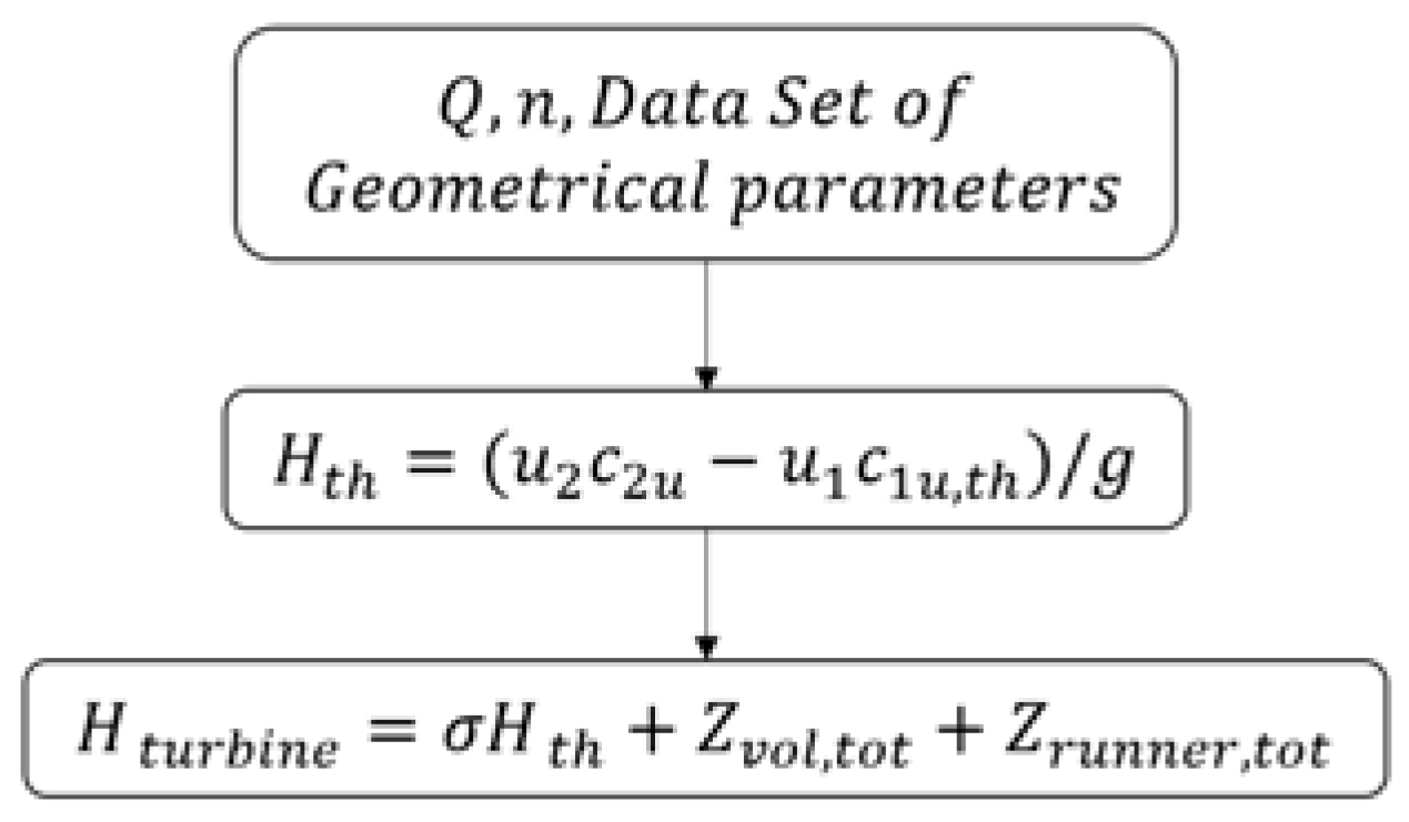
Figure 1 schematically shows how the proposed model works: thanks to the knowledge of detailed geometrical data, flow rate,
, and rotational speed,
, it is possible to accurately calculate the correct velocity triangles and the theoretical head,
, in reverse mode operation. Afterwards, volute and runner losses are modelled to finally predict the real PaT head,
.
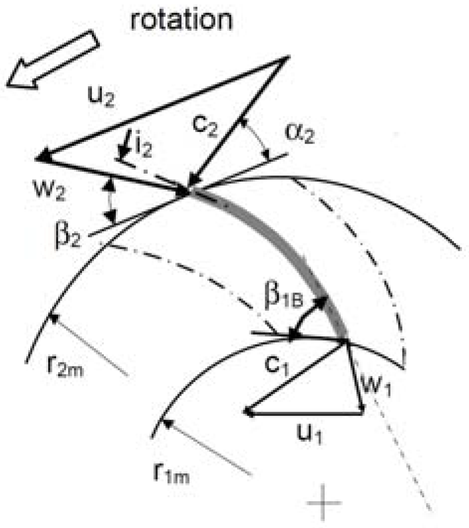
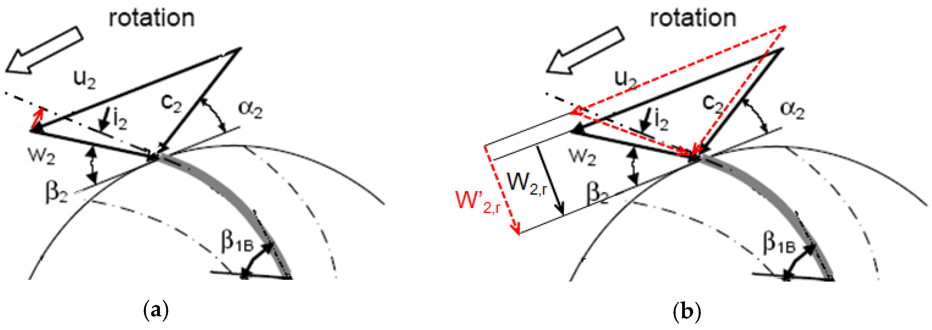
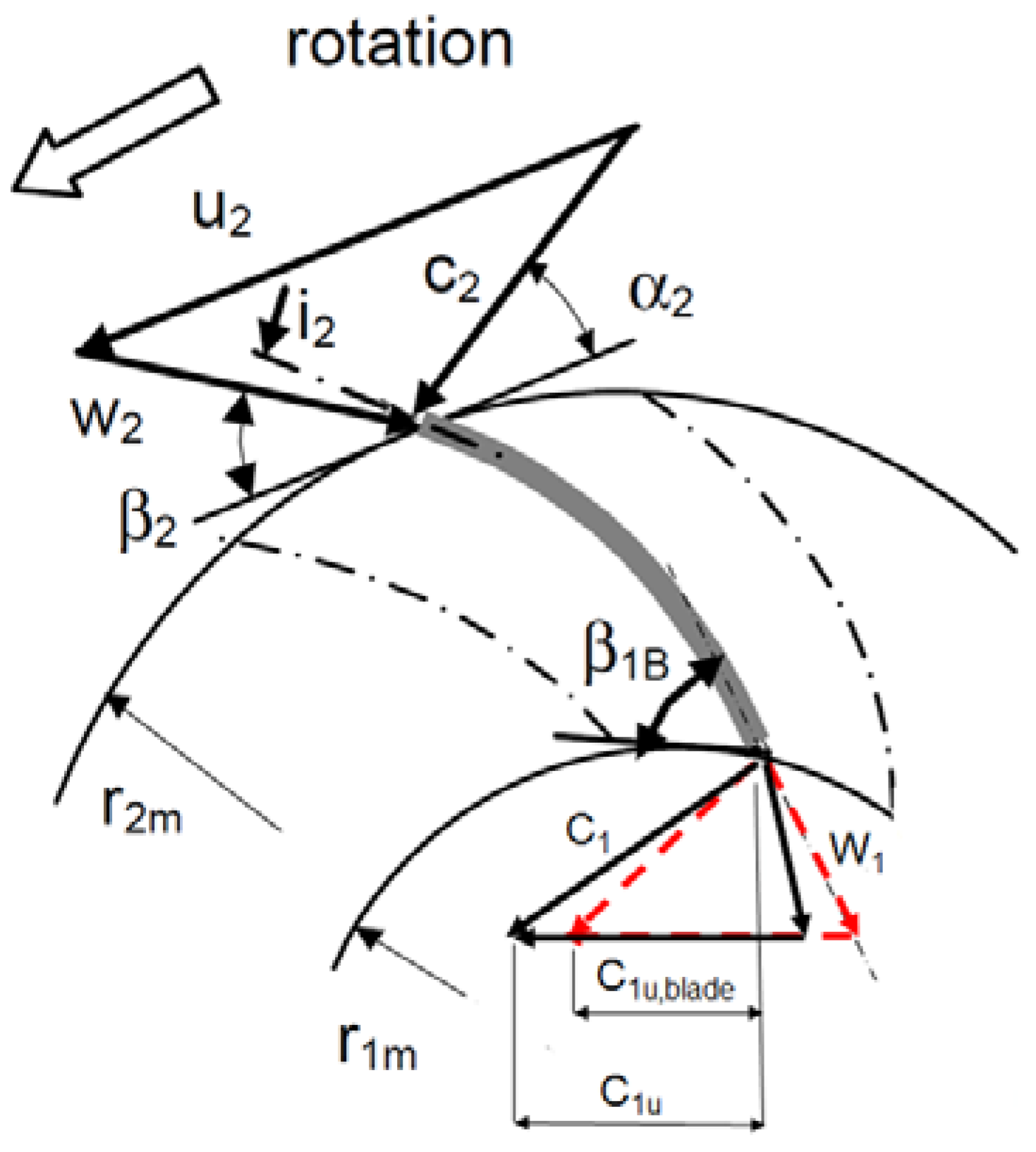
Figure 2 depicts typical velocity triangles in turbine mode. According to Gülich, the proposed model leaves unchanged for PaT the conventional section numbers used for pumps: 4 for the volute inlet or the discharge nozzle, 3 for the throat volute section, 2 for the inlet runner section, 1 for the outlet runner section. In
Figure 2,
,
and
are the relative, the absolute and the tangential velocities, respectively. The absolute and the relative flow angles are
and
, respectively, whereas
is the incidence at the leading edge of runner blade.
If compared to Gülich’s approach, the introduction of a detailed geometry, instead of a simplified geometry, requires the use of new hydraulic parameters, which allow a better prediction of the turbine head. These parameters are: (1) the flow incidence loss at the inlet section of the runner; (2) the blade blockage factor that influences the inlet velocity triangles, causing the contraction of the inlet cross section area, hence a loss due to the variation of the radial velocity component; (3) the slip factor, , i.e., the ratio between the real, , and the theoretical turbine work, . This last parameter contemplates the influence of a limited number of runner vanes on the flow deflection with respect to the outlet blade angle during turbine mode operation. Actually, this deflection causes a reduction of the Euler’s work.
The results of the new prediction model have shown a more accurate prediction of the PaT performance, under design and off-design conditions, than the results of other prediction models found in the literature.
3. Theoretical Work
As already said in the previous chapter, the first step of the model is to calculate the theoretical head,
, of the PaT by evaluating velocity triangles in both inlet and outlet sections of the runner. The objective is to calculate the circumferential components of the absolute velocities,
and
, in order to estimate the theoretical work,
by means of Euler’s equation:
3.1. Section 3: Volute Throat Area
During turbine mode operation, the fluid flows across the machine in a reverse mode. Before entering the runner, the flow is guided by the pump volute. The correct knowledge of the volute throat areas is important for the calculation of the fluid velocity in the volute. Indeed, some researchers [
10,
11] consider a square shaped area instead of the real shape of the volute throat area, which could be for example trapezoidal. This assumption overestimates the fluid velocity. Thus, it is possible to calculate fluid velocity in this section,
, by knowing the flowrate,
, and the volute throat area,
. Its circumferential component is
, where
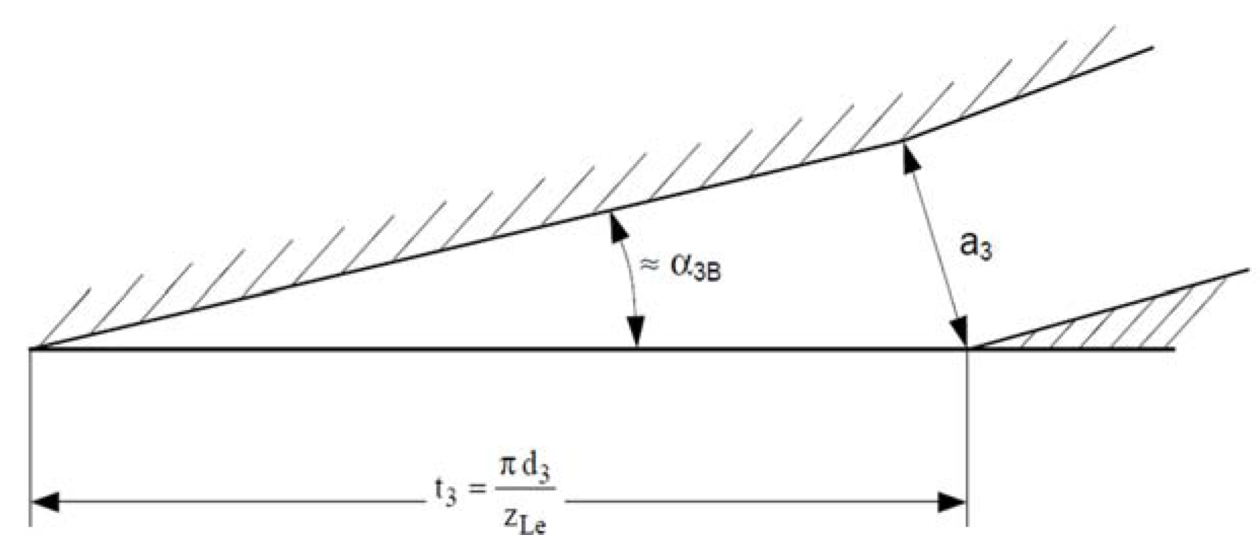
is the outflow geometrical angle from the throat area. The blade angle,
, can be estimated from the throat volute height,
, and the pitch,
, as depicted in
Figure 3. As proposed by Gülich, since
is a relatively small angle, errors in assuming
have a negligible effect on
.
3.2. Section 2: Runner Inlet Section
The flow rate entering the runner is reduced by the effect of the volumetric efficiency, , due to leakage losses.
Thanks to the knowledge of the mean outer diameter,
, the axial width,
, and the number of blades,
, of the runner channels, it is possible to calculate the inlet cross area of the runner,
A2. For double-exit impellers (double suction impellers or double discharge runners),
and
are defined per side of the impeller.
Once
is calculated, it is possible to evaluate the inlet velocity triangle. Indeed, the first step is to calculate
. The circumferential component
is obtained by applying the free vortex theory:
where
is the average outlet radius and
is the effective radius of the centre of the volute throat area [
10]:
In Equation (4), is an empirical coefficient (0.5), which contemplates the aspect ratio of the volute throat area, whereas is the height of the volute throat area and is the volute tongue thickness. Thus, knowing , and the tangential velocity, , it is possible to calculate the absolute, , and relative, , fluid angles.
3.3. Section 3: Runner Outlet Section
Also for the outlet section of the runner, the cross area
is calculated by means of the mean outlet diameter,
, the radial width of the channel,
, and the blade blockage factor,
.
Knowing flow rate flowing through the runner, , and the cross area, , the meridian component of the relative outlet velocity, , is obtained. Thanks to the outlet blade angle, , the circumferential component of the theoretical relative velocity, , can be calculated. Thus, the theoretical absolute circumferential component can be obtained by means of and .
Finally, it is possible to calculate the theoretical head, , with Equation (1).
4. Volute Losses
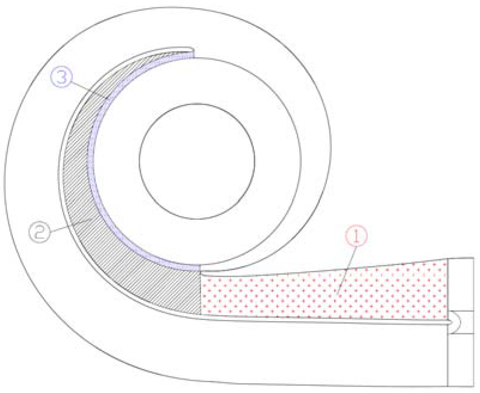
Figure 4 shows a generic double volute constituted by the inner and the outer volute. Volute losses are evaluated for the inner volute because of the inner volute losses are assumed equal to the outer volute losses. In
Figure 4, the inner volute has been divided into three parts: the inlet convergent channel (part 1), half volute collector (part 2) and the vane-less space between the throat volute section and the runner inlet section (part 3).
Generally, two kinds of losses are considered in the volute: friction losses,
, and dynamic losses,
, both determined in terms of flow rate,
Q, according to the following formulas:
Head loss coefficient in the inlet convergent nozzle,
, is calculated by means of Equation (8):
The discharge nozzle is a convergent channel, which starts from the discharge
Section 4 and ends in the throat volute
Section 3.
In Equation (8), and are mean velocity, mean length and mean hydraulic diameter of the inlet convergent channel, whereas is a loss coefficient, which contemplates losses due to the sudden geometrical expansion after the throat volute section. is the friction coefficient that depends on the Reynolds number and the relative roughness.
The loss coefficient for the volute is calculated by means of the following Equation (9):
In this case, the volute is divided into parts and their wetted surface and mean velocity in the volute, , are calculated.
As suggested by Gülich, friction losses in the vaneless space,
, are calculated by Equation (10).
Finally, the total volute head loss,
, is obtained by summing up all the volute loss contributes:
5. Runner Losses
Runner losses have different contributes. The first,
, is connected to the friction loss coefficient inside the impeller channel. As suggested by Gülich, this coefficient could be calculated by means of Equation (12):
where
is the average relative velocity between
and
and
is the corrected friction loss for flat plates.
With respect to the Gülich’s approach, the current model introduces new hydraulic parameters, which allow a better prediction of the turbine head under off-design operating conditions: (1) flow incidence losses at inlet section of the runner,
Runner,2 (
Figure 5a); (2) blade blockage factor that influences inlet velocity triangle, causing the contraction of the inlet cross-area, hence a loss due to the variation of the radial velocity component,
Runner,3 (
Figure 5b); (3) the slip factor,
, i.e., a parameter which depends on the difference between the actual tangential velocity and the theoretical flow tangential velocity at the outlet section of the runner.
This last parameter contemplates the influence of the flow deflection with respect to the blade congruent flow angle at the outlet of the runner during turbine mode operation. This deflection causes a reduction of the work due to the finite number of runner vanes, which are not able to guide perfectly the flow.
Finally, the total runner head loss,
, is obtained by summing all these contribute:
6. Slip Factor
Similarly to centrifugal pumps, also in turbines with a limited number of vanes, as in the case of PaT, a slip phenomenon occurs at the outlet section of the runner [
12].
With regard to this aspect, there are few works in the literature, which have investigated in detail the effect of the slip phenomenon in PaTs. Indeed, the evaluation of the slip effect is difficult and there are not many experimental correlations.
Ventrone [
12] focused on the slip effects at the outlet section of Francis turbines. He showed that Busemann’s results, obtained for centrifugal flows into radial blade vanes, are also valid for a centripetal flow. In order to model this phenomenon, numerical simulations have been performed by Capurso et al. [
13], highlighting the flow deflection with respect to the blade congruent flow angle at the outlet of the runner during turbine mode operation. As shown in
Figure 6, this deflection involves the increase of the absolute tangential velocity component of the absolute velocity,
, causing a decrease in terms of work done by the turbine.
The proposed model considers the slip factor,
, i.e., the ratio between the real work here obtained by CFD,
, and the theoretical work,
, under the hypothesis with a perfectly guided flow.
Capurso et al. [
13] have correlated the slip factor,
, with respect to the ratio between the flowrate,
, and the flowrate at BEP in pump mode,
:
As results, the turbine head is lower than the theoretical head due to the increase of the circumferential component of the absolute velocity at the outlet section of the runner.
7. Results and Discussions
The proposed model for the prediction of the characteristic curve of a centrifugal pump operating as a turbine has been applied to a double suction centrifugal pump of Nuovo Pignone (
9.928 in). The proposed 1-D model has been compared with other models in terms of prediction of the characteristic curve. Indeed,
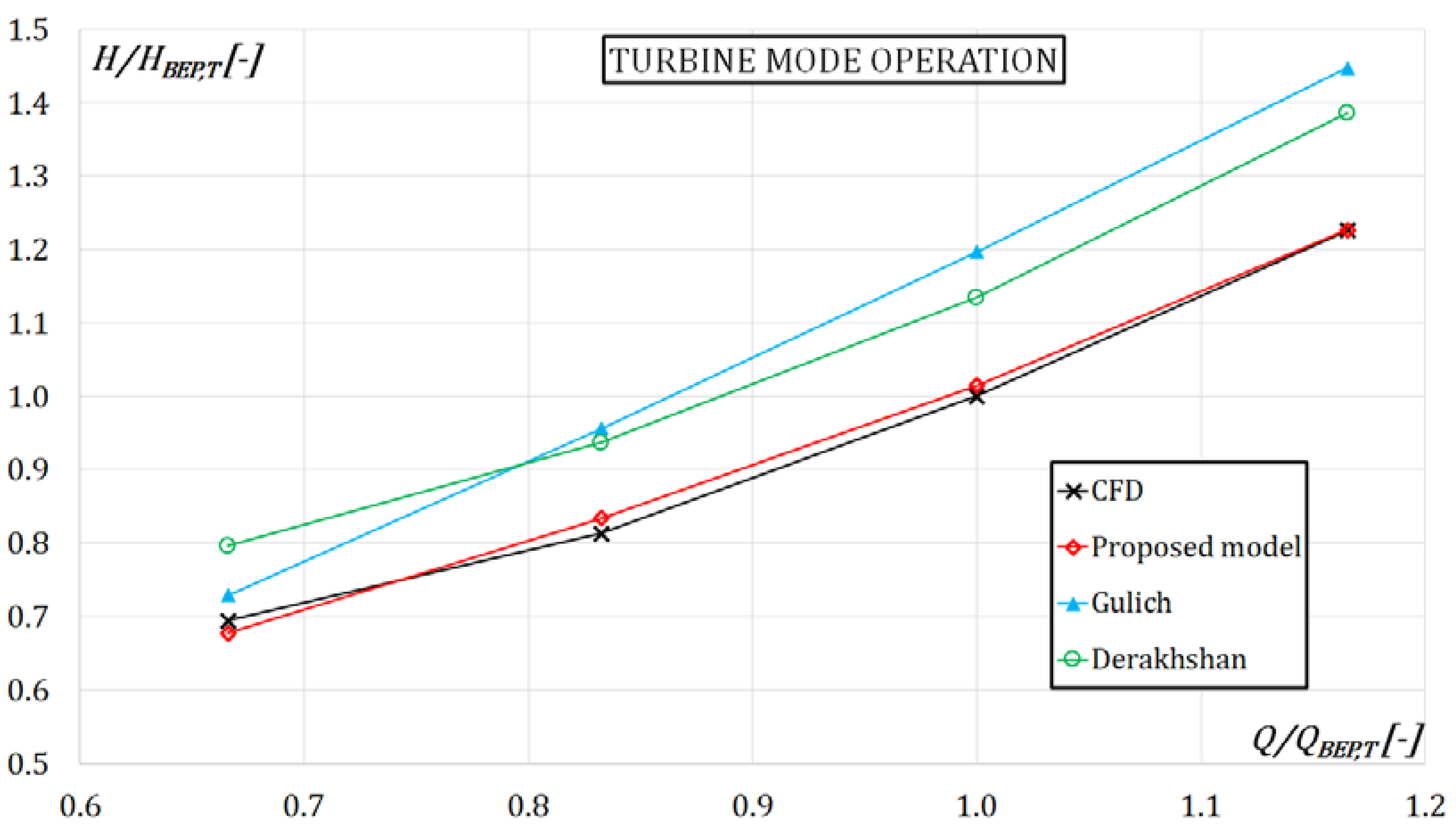
Figure 7 shows the comparison between the proposed model, the Gülich’s model and the Derakshan’s model in the prediction of the characteristic curve during turbine mode. All predicted curves have been compared with respect to that obtained by means of a numerical simulation. As result, the use of detailed geometrical information, the introduction of a slip factor and a new modelling of the hydraulic losses have involved a more accurate prediction of the PaT performance under design and off-design conditions. Indeed, the proposed 1-D model shows the best prediction at the lowest and the highest discharges (respectively equal to −2% and 0.1%) with respect to Derakshan’s (respectively equal to 14.7% and 13.1%) and Gülich’s models (respectively equal to 5% and 18%).
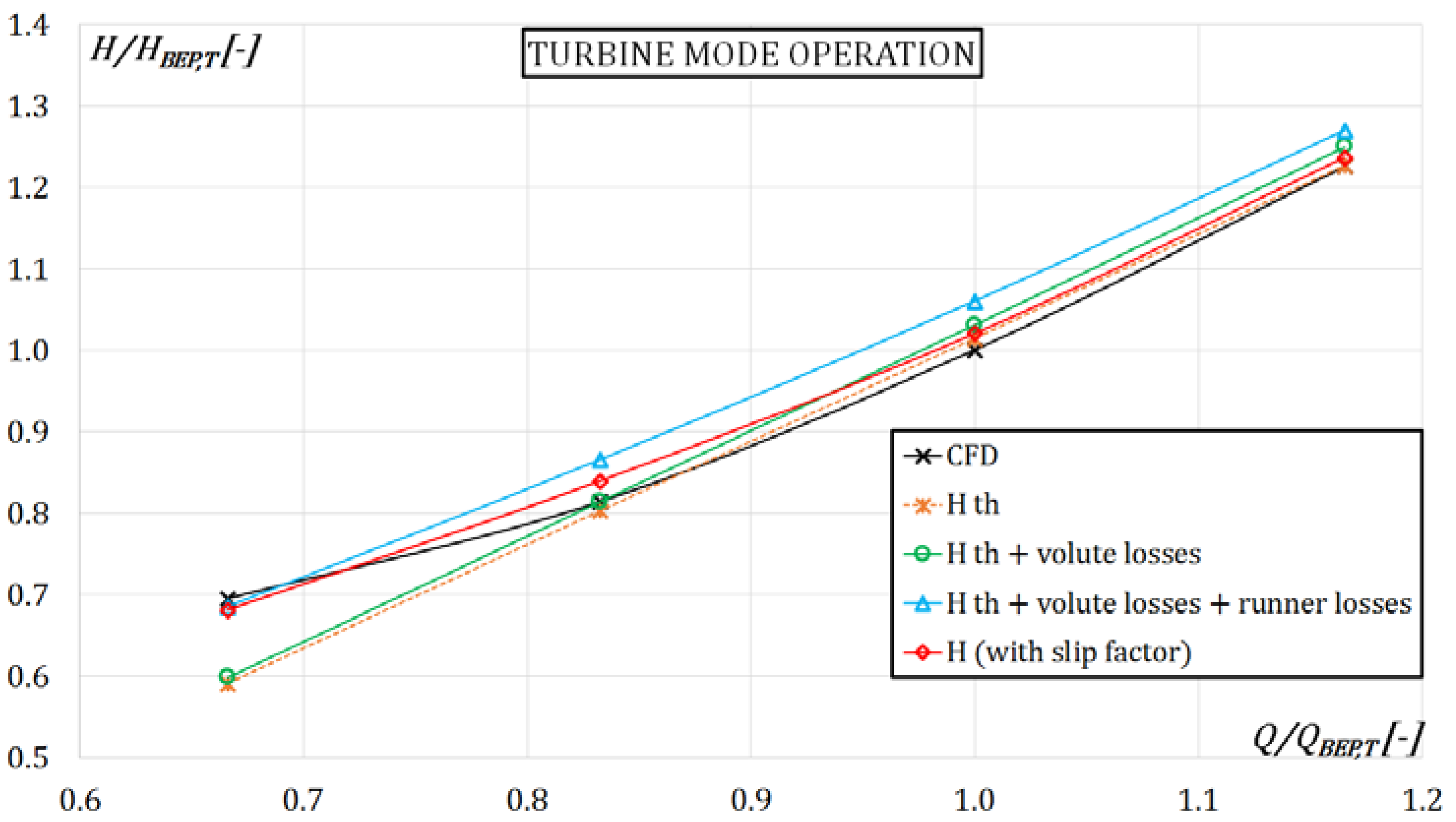
Figure 8 shows the contribution of the different hydraulic aspects introduced in the proposed model in order to predict the characteristic curve obtained by CFD. The introduction of volute and runner losses causes an increasing of the turbine head, whereas the slip factor decreases the theoretical work calculated by means of Euler’s equation and thus, involves a better prediction for the different operating points. Furthermore, the flow incidence loss and the variation of the radial component of the relative inlet velocity show their remarkable contribution at lower flow rate.
8. Conclusions
Thanks to the partnership with a leader company in the pump manufacturing, Nuovo Pignone, a new theoretical 1-D model has been proposed in order to predict the entire characteristic of a PaT, starting from the knowledge of its geometrical parameters. Thanks to these inputs, it was possible to accurately model the head losses and actual velocity triangles. With respect to the Gülich’s approach, this model introduces the use of a detailed geometry and new hydraulic aspects: flow incidence losses at the runner inlet section allows a better prediction of the turbine head under off-design operation points; the inlet velocity triangle is also influenced by the blade blockage factor. Thus, this causes the restriction of the inlet cross area, hence a loss due to the variation of the radial component of the triangle. Furthermore, numerical simulations under reverse mode operation have highlighted a flow deflection with respect to the runner outlet blade angle. This deflection causes the reduction of the theoretical turbine work. This phenomenon is taken into account by means of a slip factor, i.e., the ratio between the real work here obtained by CFD and the theoretical work obtained with geometrical blade angle. The novel prediction model has been compared with other consolidated models (Gülich’s and Derakshan’s) in terms of prediction of the characteristic curve. As results, the use of detailed geometrical information and the introduction of the slip factor and a new modelling of hydraulic losses implied a more accurate prediction of the off-design operating points.

 ,
, 


