DC Current Beat: Wireless and Non-Invasive DC Current Sensing Scheme †

Advanced Wireless and Communication Research Center, The University of Electro-Communications, Tokyo, 182-8585, Japan
*
Author to whom correspondence should be addressed.
†
Presented at the Eurosensors 2017 Conference, Paris, France, 3–6 September 2017.
Proceedings 2017, 1(4), 567; https://doi.org/10.3390/proceedings1040567
Published: 24 September 2017
(This article belongs to the Proceedings of Proceedings of Eurosensors 2017, Paris, France, 3–6 September 2017)
Abstract
:This paper presents a wireless and Non-invasive DC Current (DCC) sensing scheme as an IoT sensors. A RF module transmits only ID codes to a receiver, and the ID transmissions are called as “DCC Beat”. The interval time of DCC Beats depend on the inductance of ferrite clamp which is non-invasively installed at the wire of the DC current to be measured, so that the interval time corresponds to DC Current. The ID data transmission range reaches up to 50 m with 1.2 mW operating power using a 2.4 GHz RF module. DC current from 0.2 to 4 A can be measured within error of 5.7%.
1. Introduction
For non-invasive DC current measurement, Hall Sensor with ferrite clamp is often used [1]. We have proposed Power Beat Sensor [2] and Temperature Beat Sensor [3] as energy harvesting wireless sensors for IoT applications. This paper first demonstrates DC Current Beat Sensors, in which wireless and non-invasive DC Current (DCC) sensing can be successfully realized, so that it is used as IoT sensors at such various kinds of applications as HEMS, BEMS, DC motor control, Solar Cell control, charge control on secondary batteries, and smart grid using DC power supply. In the DCC Beat Sensors, only ID signal is transmitted by an RF transmitter, the interval time of the ID signal corresponds to the DC current to be measured.
2. Structure of the DCC Beat Sensor
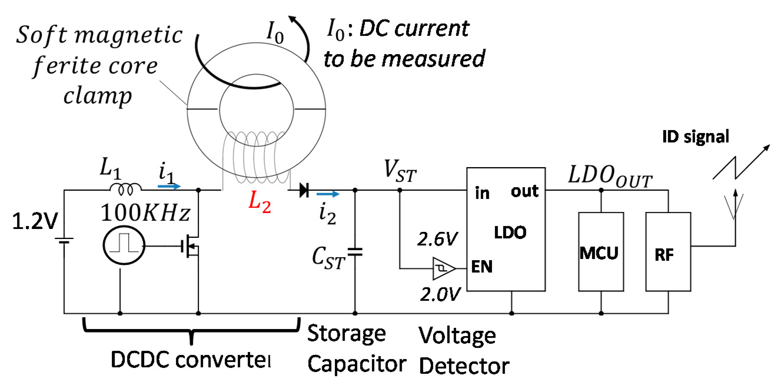
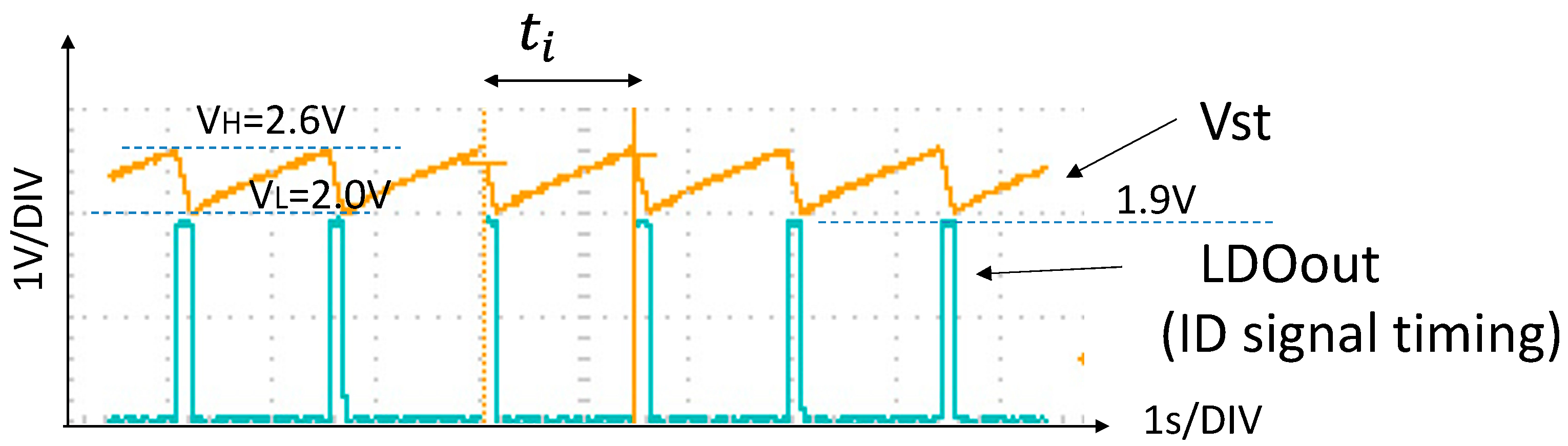
The simple circuit for the DCC beat generations consists of DCDC converter, storage capacitor, Voltage Detector (VD), Low Dropout Regulator (LDO), and MCU and a 2.4 GHz RF module [4], and no ADC is required as shown in Figure 1. As shown in Figure 2, voltage of 1.2 V is leveled up to higher voltages by a switching circuit with an inductances of L1 in the DCDC converter, and the storage capacitor CST is charged up. When Schmitt trigger VD detects the predetermined high value VH of 2.6 V, the LDO is turned on and it supplies LDO out of 1.9 V, which corresponds to the supply voltage of the MCU and the RF module. Then ID transmission is carried out by the RF module. After the ID transmission is finished, the LDO is turned off. Then the storage capacitor is charged up again followed by the next ID transmission. We use two inductances, where L1 is fixed value, and L2 is depending on DC current (Io) to be measured.
When the nMOS switch at the DCDC converter is on, the current I1 flows on the constant inductance L1, so that energy stored in the inductance L1 becomes E1 as shown Equation (1). When the nMOS switch turns off, the E1 is transferred to the energy on L2 and the storage capacitor CST as described in Equation (2). So the storage capacitor is charged up as nMOS is switching by the 100 KHz pulses. Interval time (ti) of the ID transmissions becomes short when the inductance L2 decreases, where L2 decreases as DC current to be measured increases.
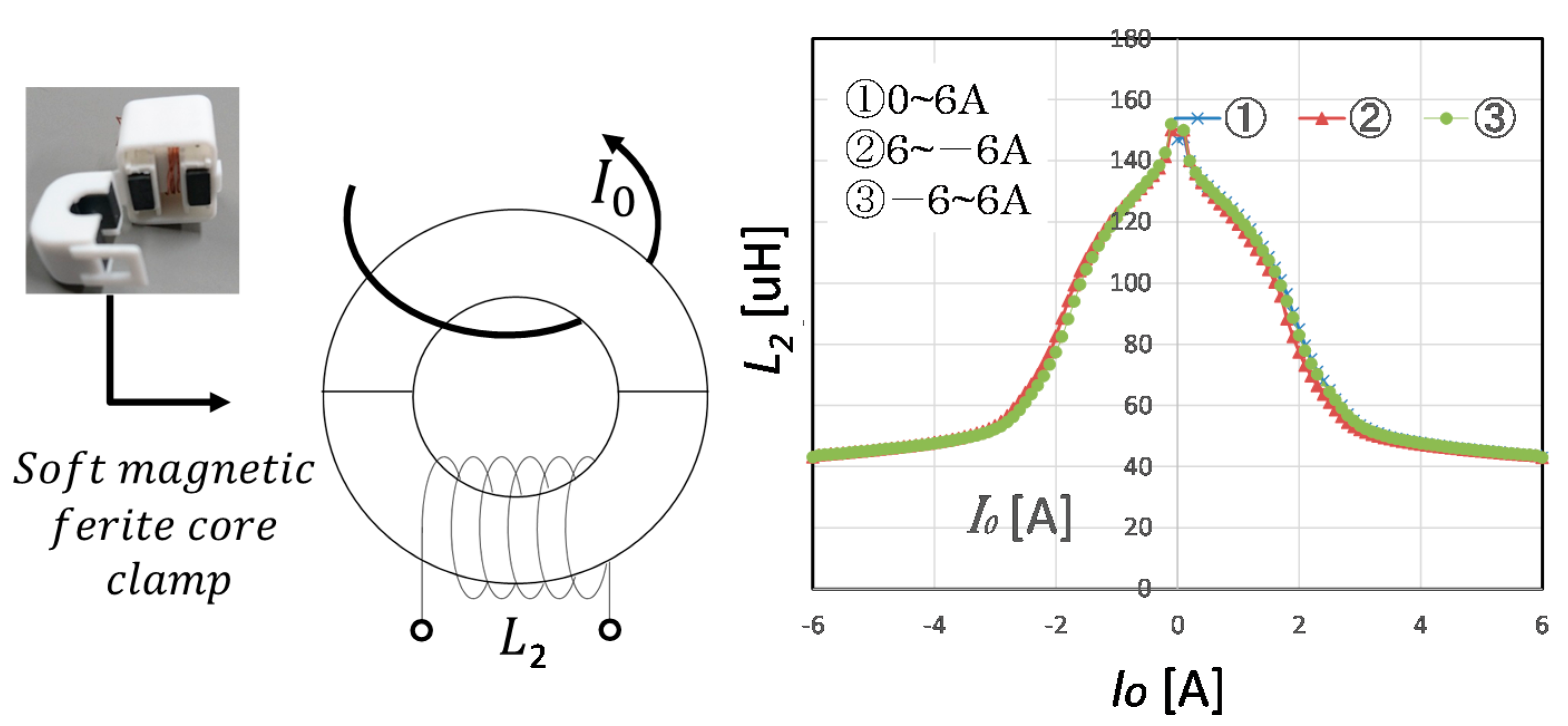
We used soft magnetic ferrite core clamp for L2 where coil for inductance is 11 turns. The inductance value is measured by LCR meter at a frequency of 100 KHz as shown in Figure 3. The maximum inductance value is 147 uH, and it decreases as DC current to be measured (Io) decreases, and little hysteresis was observed. Therefore, as the DC current increases in the circuit, the interval time ti is shortened. The interval time of the beats depends on the DC current to be measured.
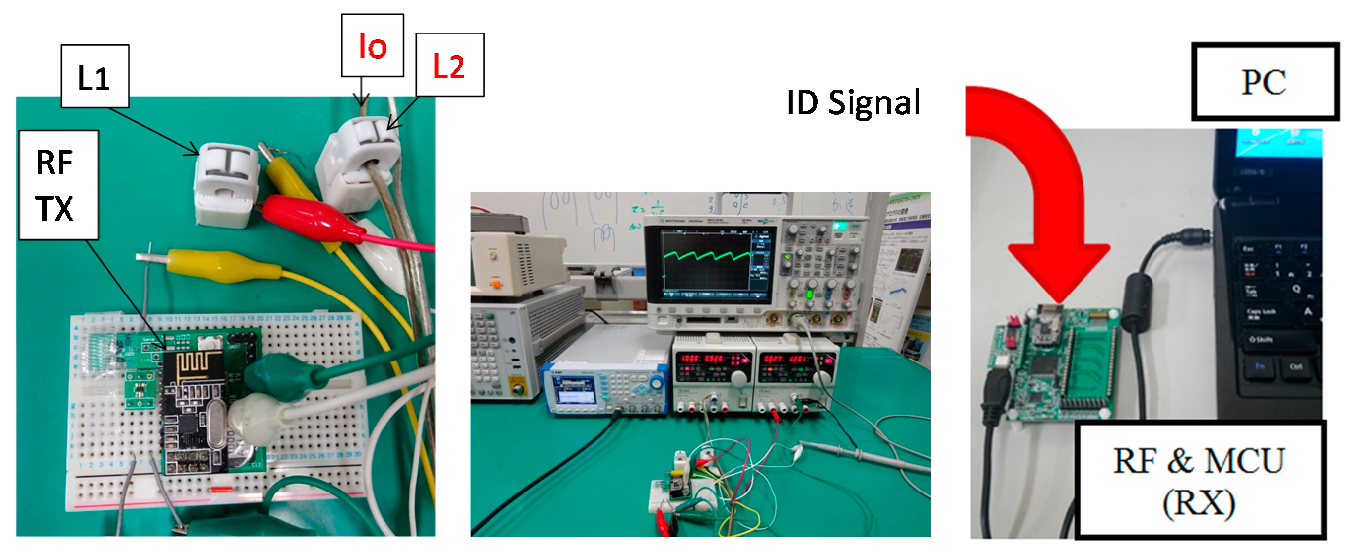
The photos of the measurement are shown in Figure 4. L1 inductance and L2 inductance are respectively made with coils around two cores of the two clamps. L1 of 18 uH, and L2 of 147 uH were respectively obtained at the Io of 0 A. The inductance of L2 depends on the DC current to be measured. A 2.4 GHz RF module (Nordic nPF24L01) with a output power of 0 dBm [4] is used to transmit the ID code for the DCC beats. Measured communication range in line of sight was up to 50 m for the RF module. The switching frequency was 100 KHz. We have successfully obtained ID signals, the interval time of which corresponds to the DC current to be measured as shown in Figure 5. The power consumption of the circuit to generate the ID signals is typically 1.2 mW at the switching frequency of 100 KHz.
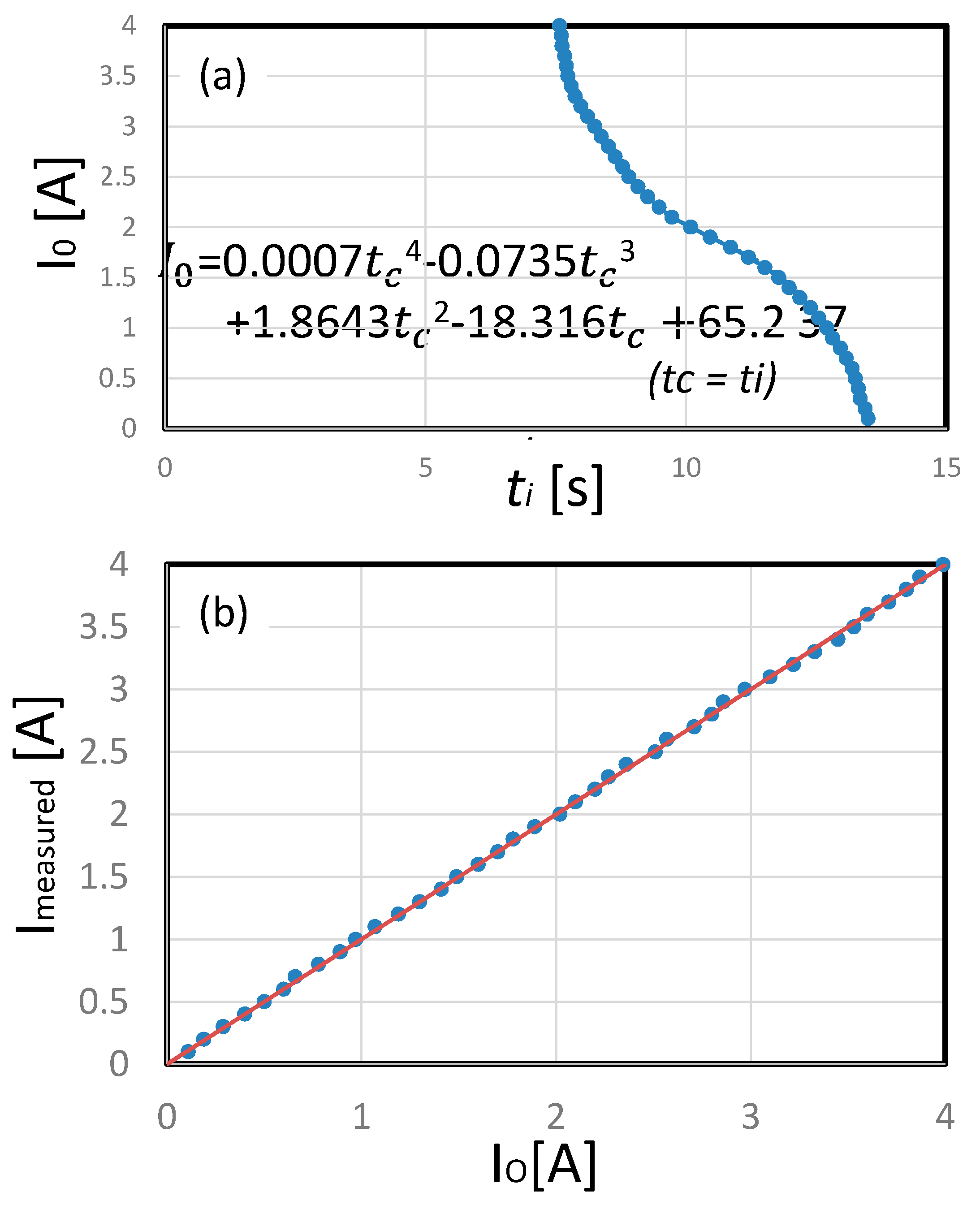
As shown in Figure 6a, the Io and ti is correlated by the 4th order of correlation formula for calibration. Measured DC current obtained by the interval time corresponds to Io, and the error is max 5.7% at DC current of 0.2 A after calibration as shown in Figure 6b.
The specifications of the DCC Beat sensors are summarized and compared to commercially available hall type DC current clamp sensor as indicated in Table 1.
Conflicts of Interest
The authors declare no conflict of interest.
References
- Available online: http://www.multimic.com/products/detail/8 (accessed on 3 August 2017).
- Ishigaki, S.; Ishibashi, K. Power Beat: A Low-cost and Energy Harvesting Wireless Electric Power Sensing Scheme for BEMS. In Proceedings of the 2015 IEEE International Conference on Building Efficiency and Sustainable Technologies, Singapore, 31 August–1 September 2015. [Google Scholar]
- Takitoge, R.; Ishigaki, S.; Ishige, T.; Ishibashi, K. Temperature Beat: Persistent and Energy Harvesting Wireless Temperature Sensing Scheme. In Proceedings of the IEEE Sensors 2016, Orlando, FL, USA, 30 October–3 November 2016. [Google Scholar]
- Available online: http://nordicsemi.com/eng/Products/2.4GHz-RF/nRF24L01 (accessed on 3 August 2017).
Figure 1.
Circuit Structure of the DC Current Beat Sensor node.

Figure 2.
Vst and LDOout waveforms by DC Current Beat Sensors.

Figure 3.
Measured inductance of the soft magnetic ferrite core clamp. The inductance depends on the DC Current which flows through the core.
Figure 3.
Measured inductance of the soft magnetic ferrite core clamp. The inductance depends on the DC Current which flows through the core.

Figure 4.
Measurement set up of the DCC Beat Sensor.

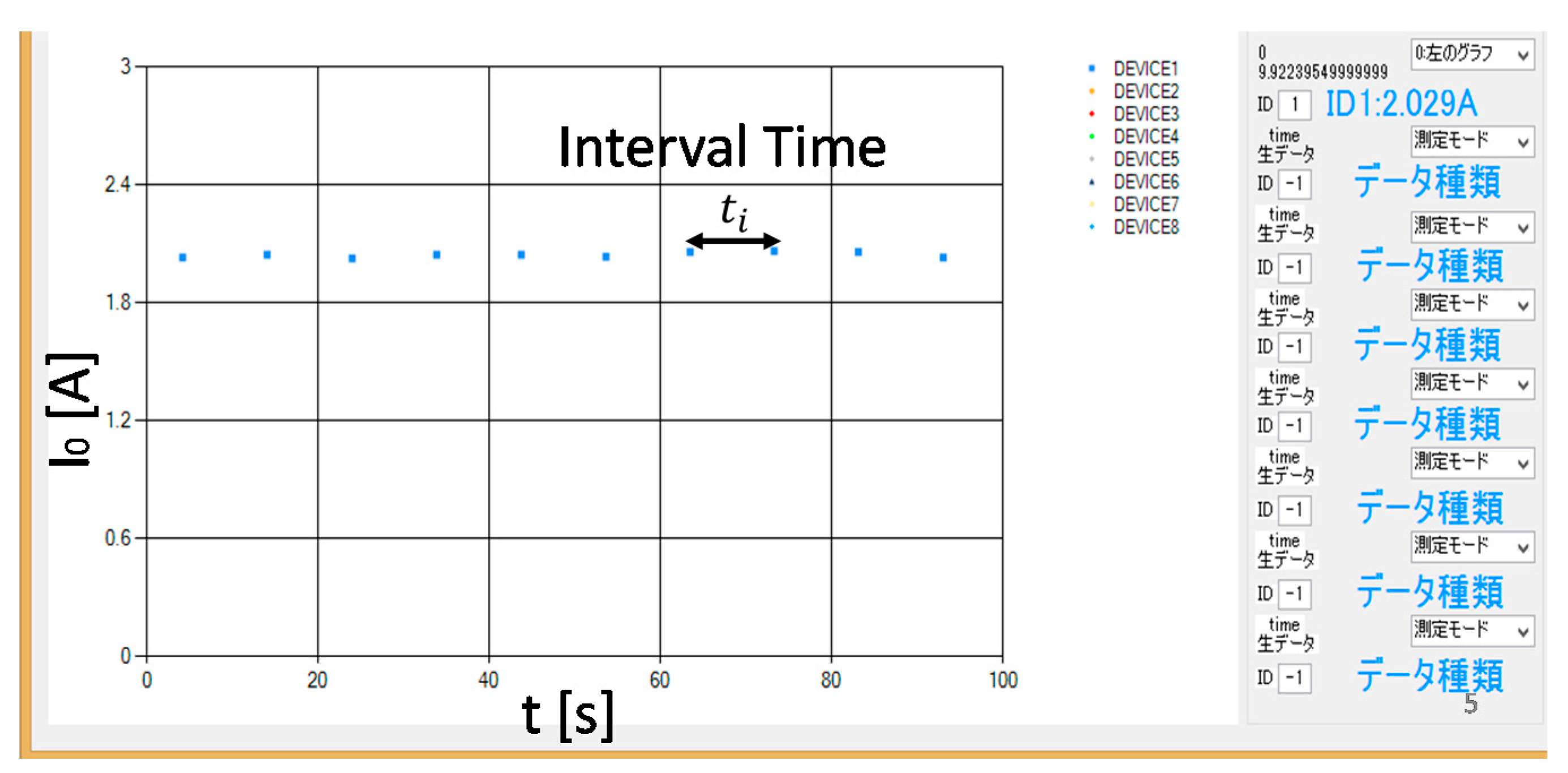
Figure 5.
Measured DC current by the DCC Beat Sensor.

Figure 6.
(a) Calibration formula for the DCC Beat Sensors; (b) Measured Io by the DCC beat sensors after calibration.
Figure 6.
(a) Calibration formula for the DCC Beat Sensors; (b) Measured Io by the DCC beat sensors after calibration.


Table 1.
Comparison Table of the DC current sensor.
| This Work | Hall Sensor (LAD-240) (1) | |
|---|---|---|
| Wired/Wireless | Wireless, up to 50 m comm. range | Wired |
| Non invasive | Yes | Yes |
| DC current range | 0.2 to 4 A | 1 to 200 A |
| Error | 5.7% after calibration | 2.5% |
| Resolution | 0.1 A | 1 A |
| Size | 40 × 50 × 20 (TX), 19 × 19 × 25 mm (Clamp) | 44 × 148 × 21 mm |
| Consuming Power | 1.2 mW | Coin Battery LR-44 × 2 |
Publisher’s Note: MDPI stays neutral with regard to jurisdictional claims in published maps and institutional affiliations. |
© 2017 by the authors. Licensee MDPI, Basel, Switzerland. This article is an open access article distributed under the terms and conditions of the Creative Commons Attribution (CC BY) license (https://creativecommons.org/licenses/by/4.0/).
Share and Cite
MDPI and ACS Style
Ishibashi, K.; Serizawa, M.; Takitoge, R.; Ishigaki, S.; Ishige, T. DC Current Beat: Wireless and Non-Invasive DC Current Sensing Scheme. Proceedings 2017, 1, 567. https://doi.org/10.3390/proceedings1040567
AMA Style
Ishibashi K, Serizawa M, Takitoge R, Ishigaki S, Ishige T. DC Current Beat: Wireless and Non-Invasive DC Current Sensing Scheme. Proceedings. 2017; 1(4):567. https://doi.org/10.3390/proceedings1040567
Chicago/Turabian StyleIshibashi, Koichiro, Makoto Serizawa, Ryohei Takitoge, Shohei Ishigaki, and Tsuyoshi Ishige. 2017. "DC Current Beat: Wireless and Non-Invasive DC Current Sensing Scheme" Proceedings 1, no. 4: 567. https://doi.org/10.3390/proceedings1040567