Tuneable Q-Factor of MEMS Cantilevers with Integrated Piezoelectric Thin Films †


Institute of Sensor and Actuator Systems TU Wien, Vienna, Austria
*
Author to whom correspondence should be addressed.
†
Presented at the Eurosensors 2017 Conference, Paris, France, 3–6 September 2017.
Proceedings 2017, 1(4), 380; https://doi.org/10.3390/proceedings1040380
Published: 21 August 2017
(This article belongs to the Proceedings of Proceedings of Eurosensors 2017, Paris, France, 3–6 September 2017)
Abstract
:When targeting the integration of atomic force microscopes (AFM) into vacuum environments (e.g., scanning electron microscopes), a tunable Q-factor of the resonating AFM cantilever is a key feature to enable high speed measurements with high local resolution. To achieve this goal, an additional stimulus is applied to the cantilever with respect to the mechanical stimulus provided by the macroscopic piezoelectric actuator. This additional stimulus is generated by an aluminium nitride based piezoelectric actuator integrated on the cantilever, which is driven by a phase shifted excitation. With this approach, the mechanical Q-factor measured with a laser Doppler vibrometer (LDV) in vacuum is electrically decreased by a factor of up to 1.7.
1. Introduction
In the last decades a huge number of silicon based MEMS (micro electro-mechanical systems) sensors and actuators were developed. Based on this effort, a broad range of different application scenarios such as sensors for the detection of chemical [1,2] or physical quantities [3,4] is covered, leading to an continuously increasing number of MEMS devices which are commercially available today. Despite their individual and application-specific design most approaches make use of either membranes or cantilevers as functional key components. Furthermore, to increase the sensitivity, many MEMS devices are operated in resonance by applying either electro-magnetic, capacitive or piezoelectric elements for excitation [5].
When making use of the latter transducer principle, a typical design consists of an aluminum nitride layer (AlN) sputter deposited on silicon (Si) and released with a support structure from the substrate [6]. Despite moderate piezoelectric constants [7], AlN is often preferred compared to zinc oxide (ZnO) or lead zirconate titanate (PZT) as functional material, as it is compatible with standard complementary metal oxide semiconductor (CMOS) microfabrication processes [8] and offers a high temperature stability [9]. Most promising application scenarios for cantilever or membrane-type micro-machined AlN devices are as density and viscosity sensors of liquids [10], as high frequency filters [11], as MEMS scanning mirrors [12] or as vibrational energy harvesters [13].
Advanced future surface analysis techniques demand a combination of scanning electron microscopy (SEM) and atomic force microscopes (AFM). This approach provides the possibility to investigate the same area of interest with both SEM and AFM. Standard AFM cantilevers that are excited by a piezo-shaker, feature a low bandwidth in vacuum due to increased Q-factors as the damping by the surrounding atmosphere is negligible compared to a standard operation in air [14]. To overcome this issue, an active tuning of the Q-factor is required.
2. Experimental Details
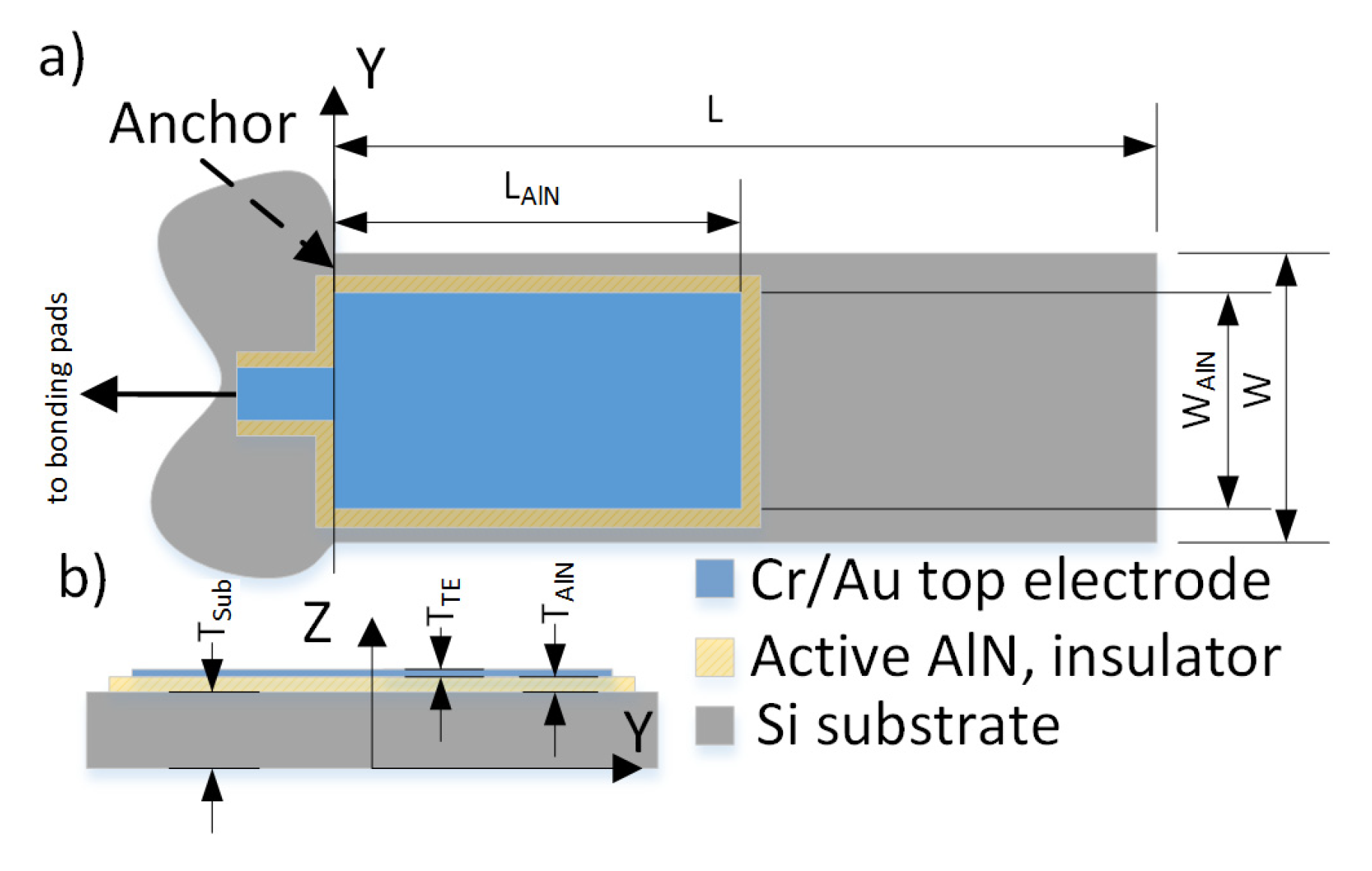
To evaluate the potential of the presented approach, a highly doped silicon-on-insulator (SOI) based cantilever with a thickness TSub of 20 µm serving as bottom electrode, is covered with reactively sputtered aluminum nitride (AlN) thin film (TAlN = 500 nm). The top electrode consists of TTE = 200 nm gold (Au) completing the piezoelectric actuator as shown in Figure 1.
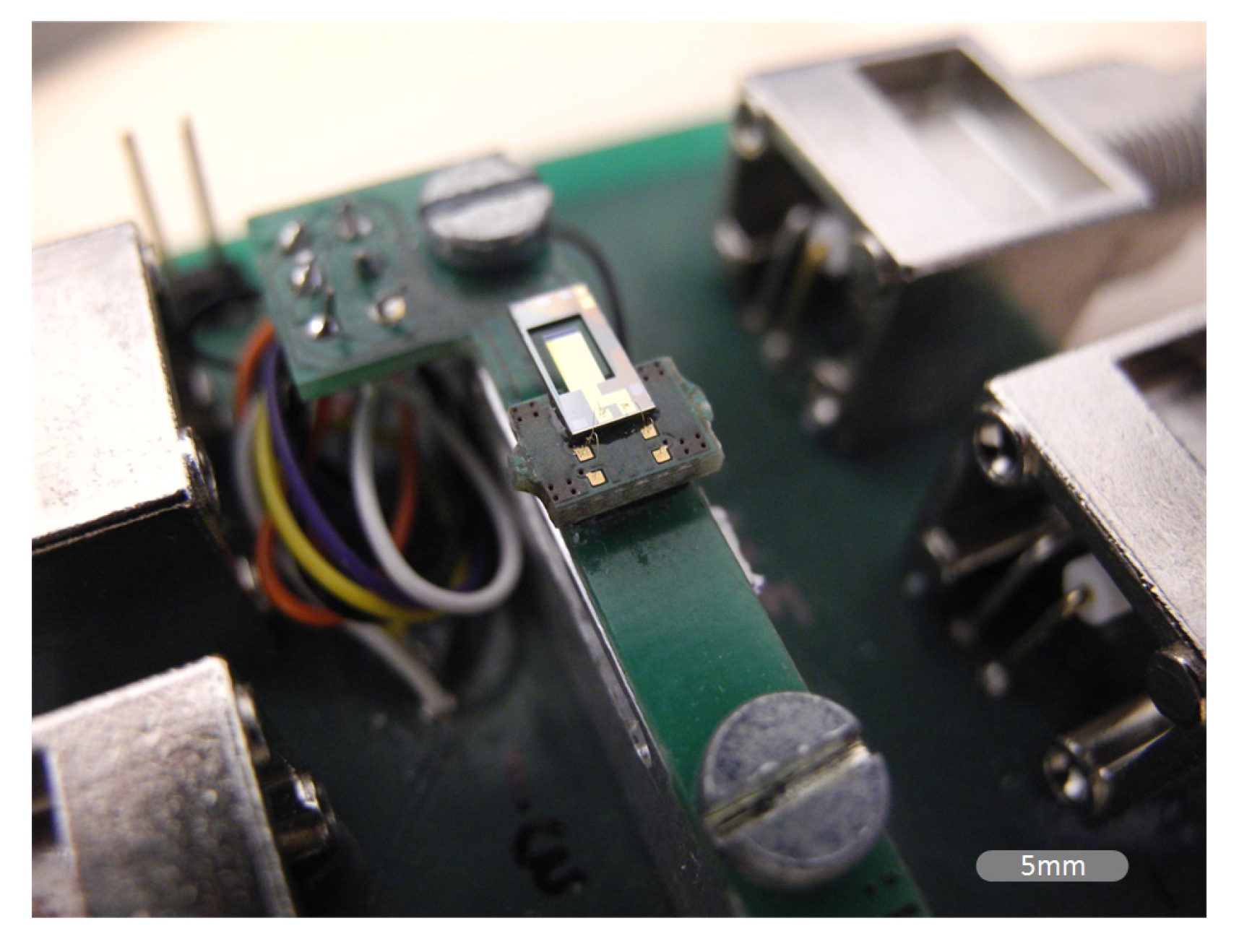
The cantilever has a length of L = 750 µm, a width W = 160 µm and is covered with AlN by a length LAlN = 200 µm. The cantilever is glued and bonded to a specially designed printed circuit board (PCB) which connects the cantilever electrically to the electrical stimulus and mechanically to the piezo shaker. The optical photo in Figure 2 shows the setup of the measurement board. To demonstrate the damping effect, the cantilever is exposed to a pressure of 6.5 × 10⁻⁵ mbar where the viscous damping of air is negligible.
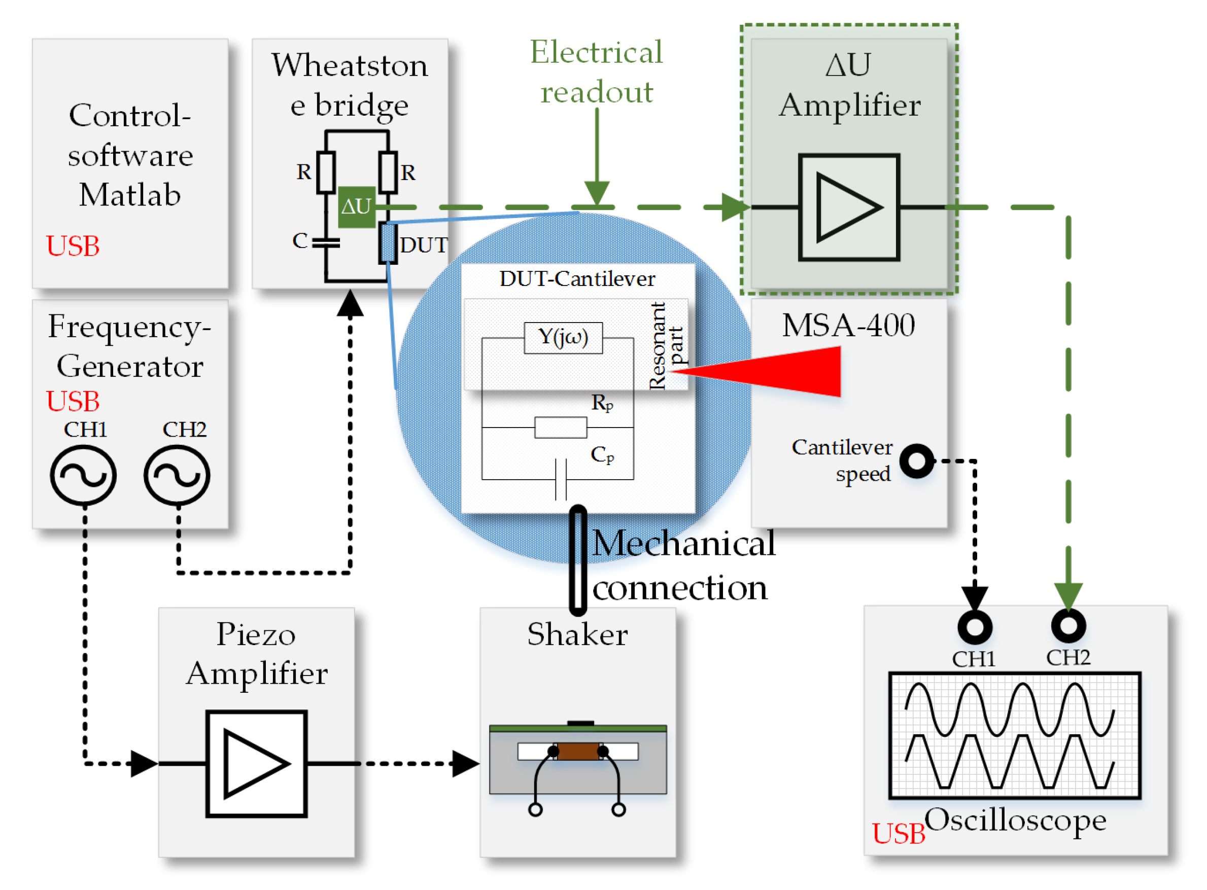
The complete measurement system is illustrated in Figure 3 and is controlled by a MATLAB script. To excite the cantilever in resonance, a piezo shaker, which is clamped in a bridge setup made out of aluminum, generates the mechanical excitation. Driven by a frequency generator (FG) and by a custom-made piezo amplifier, the mechanical excitation of this setup prevents resonances up to 100 kHz.
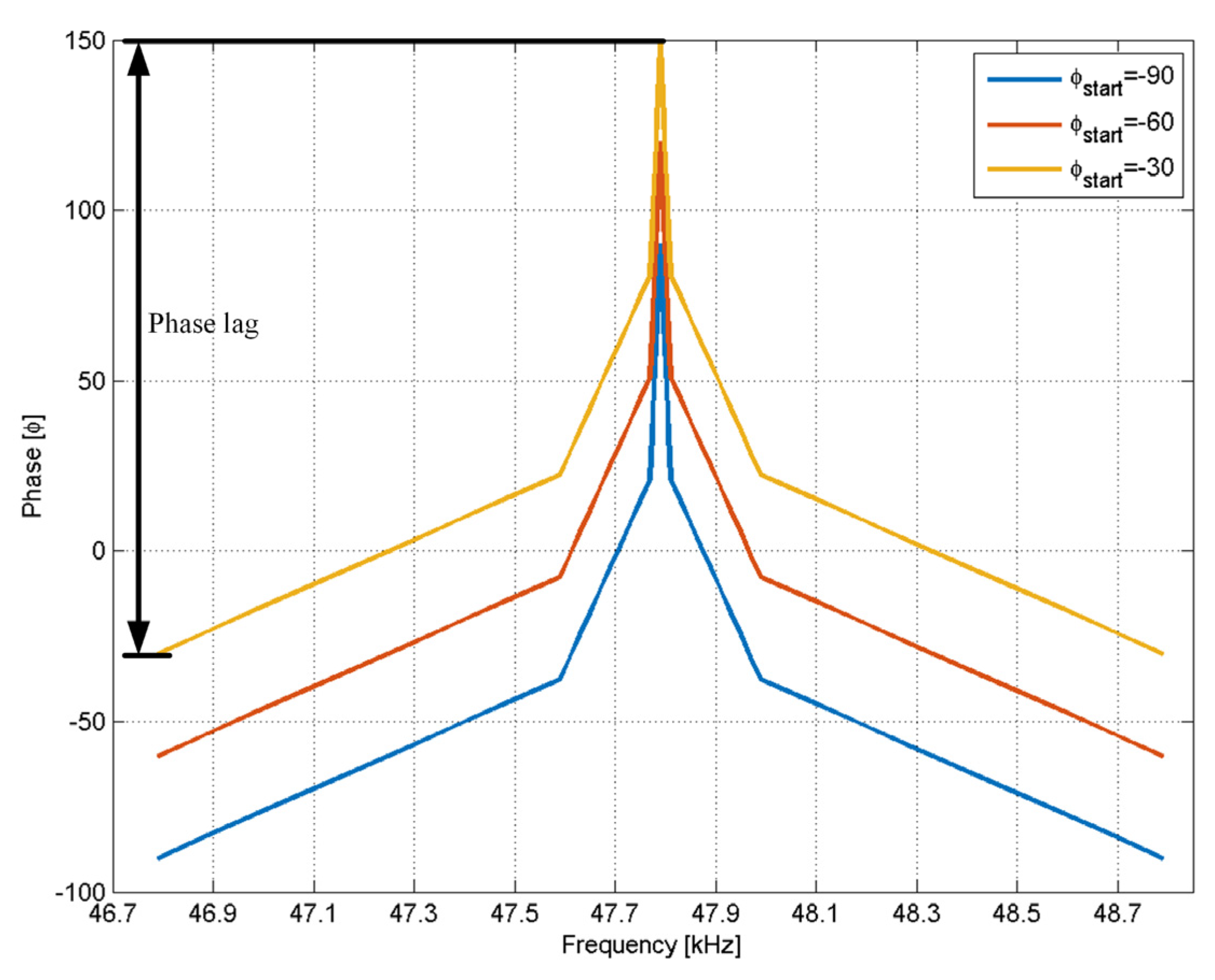
The phase lag is chosen such that it approximates a typical impedance spectrum of a MEMS cantilever resonating in the first bending mode (see Figure 4). The oscillation of the cantilever tip is measured with a laser Doppler vibrometer (LDV) (Polytec MSA400) and is recorded by an oscilloscope. The phase lag φstart of the signal supplied to the AlN actuator is varied from −90° to −30° relative to the shaker voltage and has a fixed phase lag of 180°.
3. Results
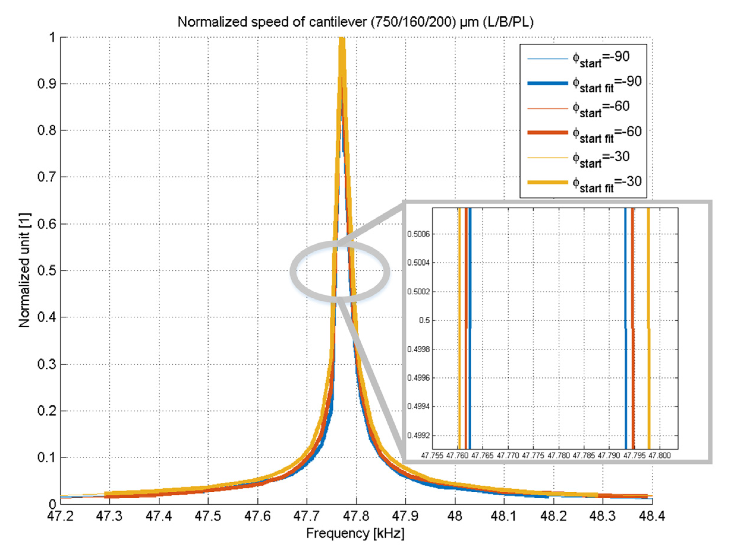
The phase shift is applied by a 2 channel FG and controlled by a MATLAB script which varies the phase shift and records the cantilever oscillation via LDV and oscilloscope. The corresponding response characteristics of the cantilever amplitudes are shown in Figure 5 which represents the normalized amplitude of the oscillation amplitude of the cantilever tip.
The Q factors for this experiment are determined by where and represent the resonance frequency and full width half maximum (FWHM), respectively. The extracted Q-factor values are presented at Table 1, starting with a value of 1080 at φstart = 0° with a constant phase lag of 0 and is reduced to 639 at φstart = −30° with a phase lag of 180° which is a reduction of the Q-factor by a factor of 1.7.
4. Summary
The setup demonstrates a clear reduction of the Q-factor due to the varying offset in phase. The optical readout represents a typical AFM device and this Q-factor tuning offers an easy-to-implement extension to existing AFM equipment. The manipulation of the phase lag between cantilever and shaker excitation results in a reduction of the Q-factor by a factor of 1.7. Future developments, indicated in green color in Figure 3, target the electrical read-out of the cantilever movement in a Wheatstone-bridge configuration and are focused on the design dependent impact of the MEMS cantilevers on the reduction in Q-factor.
Acknowledgments
We gratefully acknowledge the financial support from the ZIT Vienna “Call from Science to Products 2013” ID: 1044801.
Conflicts of Interest
The authors declare no conflict of interest.
References
- Goeders, M.K.; Colton, J.S.; Bottomley, L.A. Microcantilevers: Sensing Chemical Interactions via Mechanical Motion. Chem. Rev. 2008, 108, 522–542. [Google Scholar] [CrossRef] [PubMed]
- Dionne, R.E.; Toader, V.; Badia, A. Microcantilevers Bend to the Pressure of Clustered Redox Centers. Langmuir 2014, 30, 742–752. [Google Scholar] [CrossRef] [PubMed]
- Tadigadapa, S.; Mateti, K. Piezoelectric MEMS sensors: State-of-the-art and perspectives. Meas. Sci. Technol. 2009, 20, 092001. [Google Scholar] [CrossRef]
- Kucera, M.; Wistrela, E.; Pfusterschmied, G.; Ruiz-Díez, V.; Manzaneque, T.; Hernando-García, J.; Sánchez-Rojas, J.L.; Jachimowicz, A.; Schalko, J.; Bittner, A.; et al. Design-dependent performance of self-actuated and self-sensing piezoelectric-AlN cantilevers in liquid media oscillating in the fundamental in-plane bending mode. Sens. Actuators B Chem. 2014, 200, 235–244. [Google Scholar] [CrossRef]
- Michels, T.; Rangelow, I.W. Review of scanning probe micromachining and its applications within nanoscience. Microelectron. Eng. 2014, 126, 191–203. [Google Scholar] [CrossRef]
- Boisen, A.; Dohn, S.; Keller, S.S.; Schmid, S.; Tenje, M. Cantilever-like micromechanical sensors. Rep. Prog. Phys. 2011, 74, 036101. [Google Scholar] [CrossRef]
- Ababneh, A.; Schmid, U.; Hernando, J.; Sánchez-Rojas, J.L.; Seidel, H. The influence of sputter deposition parameters on piezoelectric and mechanical properties of AlN thin films. Mater. Sci. Eng. B 2010, 172, 253–258. [Google Scholar] [CrossRef]
- Pérez-Campos, A.; Iriarte, G.F.; Hernando-Garcia, J.; Calle, F. Post-CMOS compatible high-throughput fabrication of AlN-based piezoelectric microcantilevers. J. Micromech. Microeng. 2015, 25, 025003. [Google Scholar] [CrossRef]
- Ambacher, O. Growth and applications of Group III-nitrides. J. Phys. D Appl. Phys. 1998, 31, 2653–2710. [Google Scholar] [CrossRef]
- Kucera, M.; Hofbauer, F.; Wistrela, E.; Manzaneque, T.; Ruiz-Díez, V.; Sánchez-Rojas, J.L.; Bittner, A.; Schmid, U. Lock-in amplifier powered analogue Q-control circuit for self-actuated self-sensing piezoelectric MEMS resonators. Microsyst. Technol. 2014, 20, 615–625. [Google Scholar] [CrossRef]
- Hemon, S.; Akjouj, A.; Soltani, A.; Pennec, Y.; El Hassouani, Y.; Talbi, A.; Mortet, V.; Djafari-Rouhani, B. Hypersonic band gap in an AlN-TiN bilayer phononic crystal slab. Appl. Phys. Lett. 2014, 104, 063101. [Google Scholar] [CrossRef]
- De Lima, M.M., Jr.; Paulo, V.S. Modulation of photonic structures by surface acoustic waves. Rep. Prog. Phys. 2005, 68, 1639. [Google Scholar] [CrossRef]
- Steven, A.R.; Henry, A.S. A review of power harvesting using piezoelectric materials (2003–2006). Smart Mater. Struct. 2007, 16, R1. [Google Scholar] [CrossRef]
- Fairbairn, W.M.; Moheimani, S.O.R.; Fleming, A.J. Control of an Atomic Force Microscope Microcantilever: A Sensorless Approach. J. Microelectromech. Syst. 2011, 20, 1372–1381. [Google Scholar] [CrossRef]
Figure 1.
Schematics of the piezoelectric MEMS cantilever. In (a) the top and in (b) the cross-sectional view are shown.
Figure 1.
Schematics of the piezoelectric MEMS cantilever. In (a) the top and in (b) the cross-sectional view are shown.

Figure 2.
Photo of the custom-built shaker mounted with a bonded MEMS cantilever. The complete set-up is placed in a vacuum-controlled chamber having an optical access for the LDV.
Figure 2.
Photo of the custom-built shaker mounted with a bonded MEMS cantilever. The complete set-up is placed in a vacuum-controlled chamber having an optical access for the LDV.

Figure 3.
The Block diagram of the measurement set-up used for characterization of the actively damped MEMS cantilevers. The electrical readout, highlighted in green, is targeted for future evaluation purposes.
Figure 3.
The Block diagram of the measurement set-up used for characterization of the actively damped MEMS cantilevers. The electrical readout, highlighted in green, is targeted for future evaluation purposes.

Figure 4.
Phase difference between the stimulating voltage at the integrated piezoelectric layer and the supply voltage at the shaker.
Figure 4.
Phase difference between the stimulating voltage at the integrated piezoelectric layer and the supply voltage at the shaker.

Figure 5.
Normalized amplitude characteristics of the cantilever tip when applying a phase shifted excitation. The inserted detail serves as guide to the eyes.
Figure 5.
Normalized amplitude characteristics of the cantilever tip when applying a phase shifted excitation. The inserted detail serves as guide to the eyes.


Table 1.
Table of Q-factors obtained by LDV measurements when applying a phase-shifted stimulus to the MEMS cantilever.
Table 1.
Table of Q-factors obtained by LDV measurements when applying a phase-shifted stimulus to the MEMS cantilever.
| φstart | Qmech |
|---|---|
| 0 (ϕconstant) | 1080 |
| −60 | 724 |
| −30 | 639 |
Publisher’s Note: MDPI stays neutral with regard to jurisdictional claims in published maps and institutional affiliations. |
© 2017 by the authors. Licensee MDPI, Basel, Switzerland. This article is an open access article distributed under the terms and conditions of the Creative Commons Attribution (CC BY) license (https://creativecommons.org/licenses/by/4.0/).
Share and Cite
MDPI and ACS Style
Fischeneder, M.; Oposich, M.; Schneider, M.; Schmid, U. Tuneable Q-Factor of MEMS Cantilevers with Integrated Piezoelectric Thin Films. Proceedings 2017, 1, 380. https://doi.org/10.3390/proceedings1040380
AMA Style
Fischeneder M, Oposich M, Schneider M, Schmid U. Tuneable Q-Factor of MEMS Cantilevers with Integrated Piezoelectric Thin Films. Proceedings. 2017; 1(4):380. https://doi.org/10.3390/proceedings1040380
Chicago/Turabian StyleFischeneder, Martin, Martin Oposich, Michael Schneider, and Ulrich Schmid. 2017. "Tuneable Q-Factor of MEMS Cantilevers with Integrated Piezoelectric Thin Films" Proceedings 1, no. 4: 380. https://doi.org/10.3390/proceedings1040380