Proceeding Paper

Development and Testing of a Dual Accelerometer Vector Sensor for AUV Acoustic Surveys †

1
LARSyS, University of Algarve, Campus de Gambelas, 8005-139, Faro, Portugal
2
Marsensing Lda, Centro Empresarial Gambelas, 8005-139, Faro Portugal
3
Instituto Superior Téchico, Institute for Systems and Robotics, 1049-001, Lisbon, Portugal
*
Author to whom correspondence should be addressed.
Presented at the 3rd International Electronic Conference on Sensors and Applications, 15–30 November 2016; Available online: https://sciforum.net/conference/ecsa-3.
Proceedings 2017, 1(2), 33; https://doi.org/10.3390/ecsa-3-E011
Published: 14 November 2016

Abstract

:
This paper presents the design, manufacturing and testing of a Dual Accelerometer Vector Sensor (DAVS). The device was built within the activities of the WiMust project, a EU project, supported under the Horizon 2020 Framework Programme, which aims to improve the efficiency of the methodologies used to perform geophysical acoustic surveys at sea by the use of Autonomous Underwater Vehicles (AUVs). The DAVS contributes to this aim in various ways, for example, owing to its spatial filtering capability, it can measure reflections at the desired direction therefore reducing the amount of post processing related to deghosting and multipath removal. Also its compact size allows easier integration with AUVs and hence facilitates the vehicle manoeuvrability compared to the classical towed arrays. The DAVS device consists of two tri-axial accelerometers and one hydrophone moulded in one unit. The device’s directional estimation capabilities were evaluated on an AUV, which was sailing around a deployed sound source. Results of this experiment are presented in this paper.

1. Introduction

Acoustic vector sensors are relatively compact sensors with spatial filtering capabilities. They measure acoustic pressure and particle velocity and usually combine these two quantities in an intensity estimation, which results in an inherently directional beam. The particle velocity can be measured directly or as a derived value from acceleration or pressure differential, see for example [1], for the underlying theory. Applications of vector sensors include target tracking [2,3], detection and estimation of Direction Of Arrival (DOA) of sound sources [4,5,6], underwater communication [7,8] and geo-acoustic inversion [9,10].
An important area of application for vector sensors is geo-acoustic surveys, where traditionally they are deployed on the earth surface or laid with cables on the seafloor. Owing to their directionality, they can distinguish between vertical and horizontal earth motions and hence they are used to record multicomponent seismic data. In sea surveys in particular, water-bottom cables with such sensors have been used for the attenuation of water-column reverberations [11]. In recent years vector sensors have been used on towed steamers for the elimination of surface reflections (ghosts) [12], however details of these developments have limited publicity as they contain commercially sensitive information. An advancement for marine geo-acoustic surveys is the replacement of the towed streamers with Autonomous Underwater Vehicles (AUV). The EU project WiMUST (Widely scalable Mobile Underwater Sonar Technology) [13], supported under the Horizon 2020 Framework Programme, aims at expanding the functionalities of the current cooperative marine robotic systems, in order to enable deployment of distributed acoustic arrays for geophysical surveying in a setup composed of a ship towing a source and a receiving array carried by AUV. These arrays consist of pressure sensors and a dedicated Dual Accelerometer Vector Sensor (DAVS) will be mounted on one of the AUVs to demonstrate its advantages in this scenario. In this paper, Section 2 describes the development of DAVS together with its main mechanical and electronic characteristics. Section 3 presents the first experimental results with DAVS in an acoustic survey scenario.

2. Methods

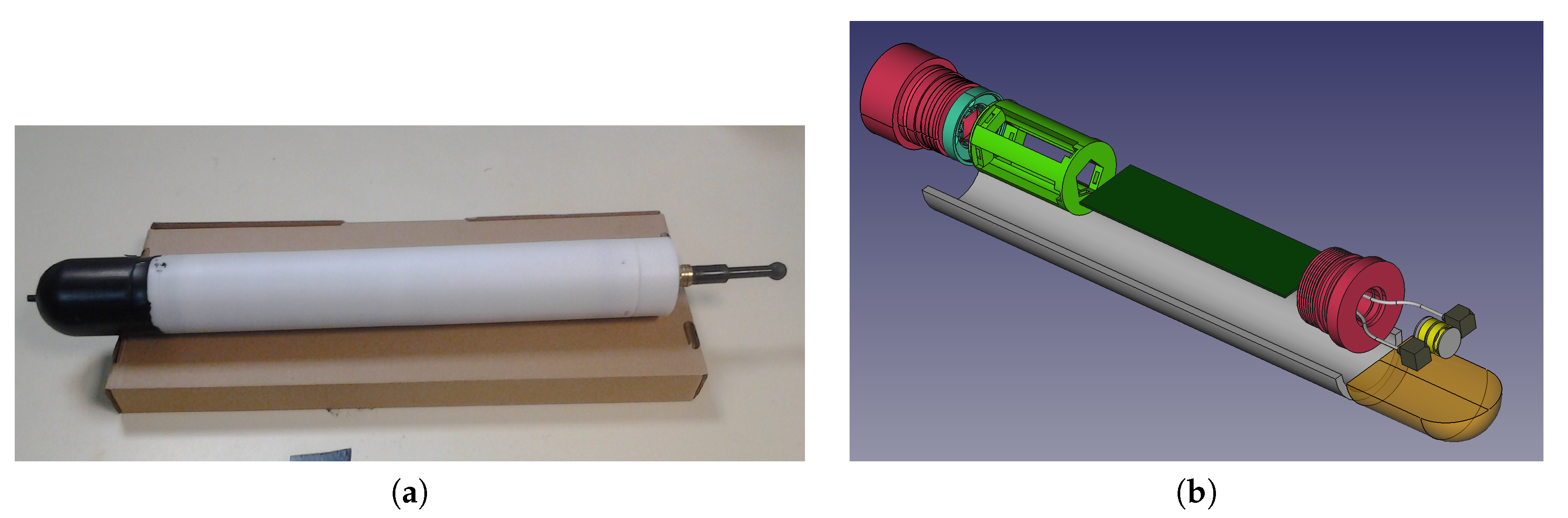
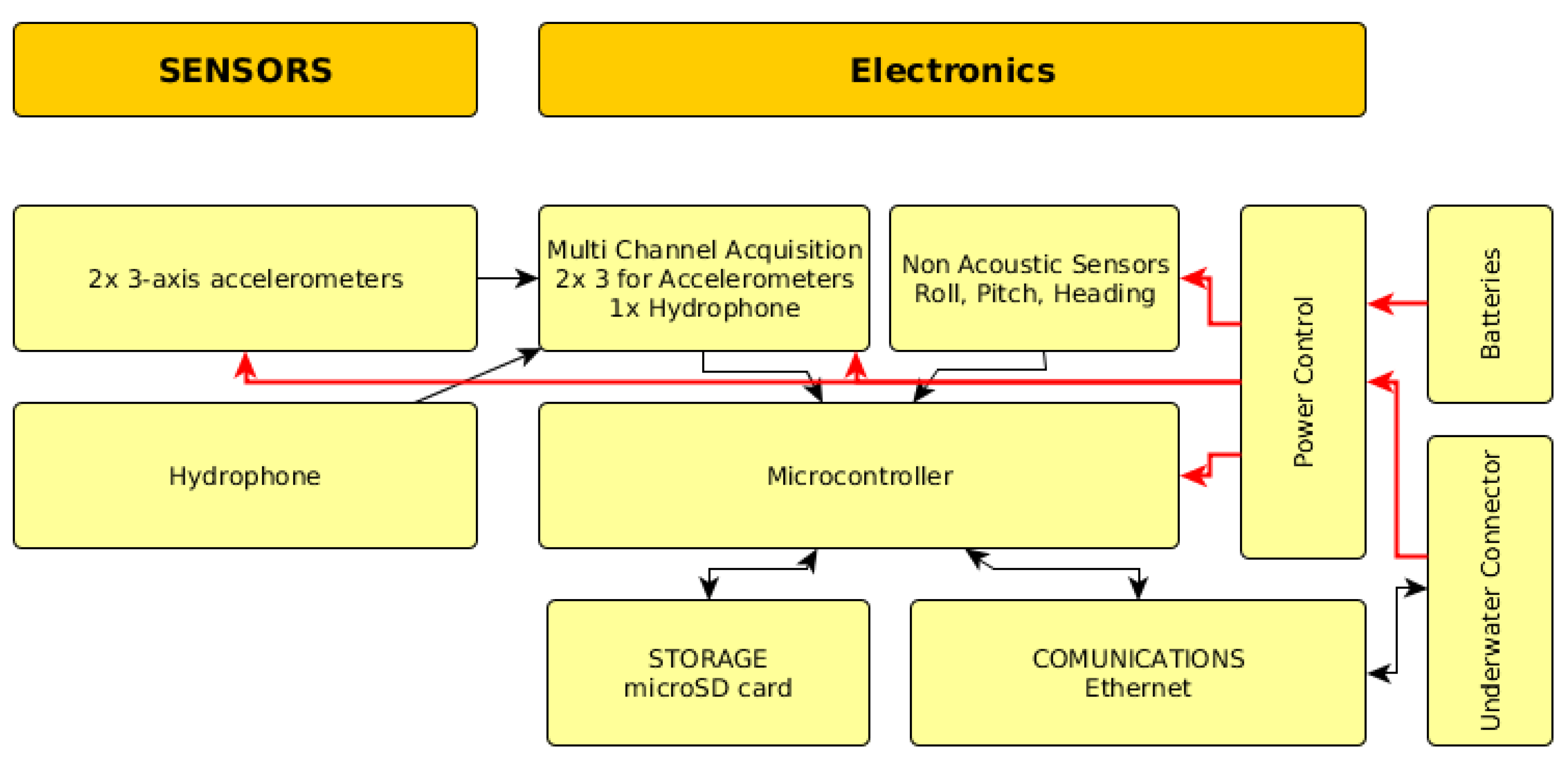
2.1. DAVS Description

A photo of the DAVS is shown in Figure 1a. The DAVS system has two main parts. The one is the acoustically active part (black nose), which contains two tri-axial accelerometers (PCB, model number 356A17) and one build in-house hydrophone. The other part is a tube made of Delrin, which houses the electronics, acquisition system and batteries. The total length of the device is 525 mm and its diameter is 65 mm.
Figure 1b shows an exploded view of a three dimensional model of the system, as built with a 3D cad solid modelling package. In this figure we discern, in the acoustically active part (in dark yellow), which represents the Polyurethane mould, the DAVS sensing elements: two accelerometers (grey blocks) either side of the hydrophone (yellow cylindrical component). The sensors are moulded together with a threaded cap (in pink), which is screwed to the cylinder which contains the electronics (here represented as a dark green block). The cylinder is closed with another threaded cap (in pink) and contains the battery pack, shown in light green colour.
The acquisition system of DAVS is a digital platform for the acoustic sensors and a non-acoustic motion sensor, the system overview is shown in Figure 2. Its electronic components include a micro-controller, an analogue multi-channel simultaneous acquisition system, data storage on a removable flash device, real time clock, non-acoustic positioning sensors for pitch, roll and heading, power management and an external communications port. Table 1 gives an overview of the DAVS system characteristics. The device can operate autonomously on batteries for 20 h and data storage in a microSD card. Alternatively it can be powered externally to a 24 V DC power supply, streaming data via Ethernet.

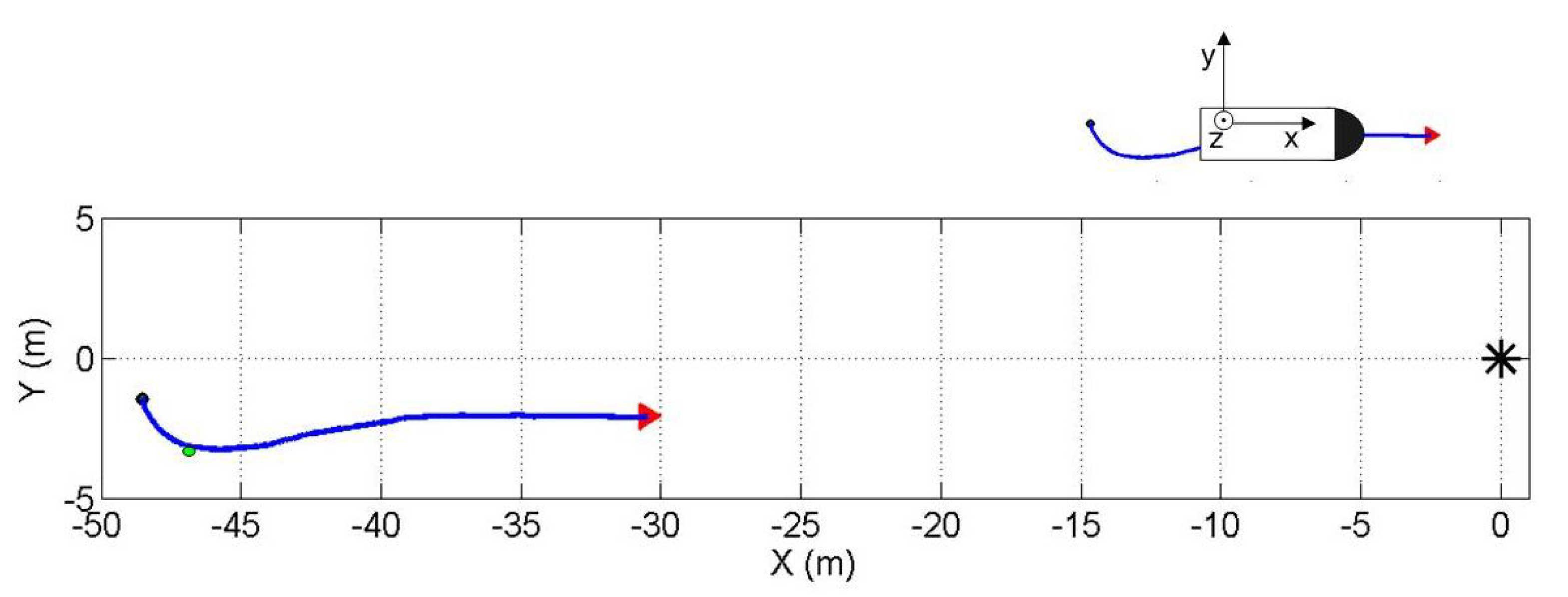
2.2. In Situ Experiments

The DAVS device was tested on an AUV, in Lisbon at the Oceanarium Marina in the Parque das Nações, where the waters were protected with a sluice from current and rough sea conditions. The objective was to evaluate the ability of the DAVS to estimate the azimuthal direction of incoming sound waves when it is in motion. The DAVS was mounted on an AUV provided by DSOR Laboratory (Instituto Superior Tecnico, IST-ID). Figure 3a shows the red MEDUSA without the DAVS and Figure 3b shows the same vehicle in inverted position with the DAVS attached to it. The AUV was sailing on the surface and was carrying a GPS antenna, the depth of the DAVS during the experiment was approximately 0.5 m.
The AUV was sailing on a pre-programmed track with a nominal speed of 0.26 m/s relative to an immersed sound source (Lubell KK916C underwater speaker), which was deployed by a rope at approximately mid-water, 1.5 m depth. Figure 4 shows the trajectory, which was referenced relative to the position of the sound source (0,0) on the experimental XY plane parallel to the sea floor. In Figure 4 the blue line shows the trajectory for the results discussed in this paper, the black dot and the red arrow indicate the beginning and the end of the track of the acoustic data presented here. The green dot indicates starting point for the azimuthal calculation using the AUV positional information from non acoustic sensors, as an independent check for the estimates obtained with the DAVS.
The sound source was emitting chirp signals from 1 kHz to 2 kHz every 0.396 s. The signals were sampled at 10547 Hz. DAVS sensor xy plane was parallel to the experiment XY plane with the positive z direction pointing upwards and the positive x in the direction of sailing, according to the right hand coordinate convention shown in the top right of Figure 4. The DAVS was positioned on the AUV such that the two accelerometers were aligned with the vertical, z axis. In this set up, two estimations were obtained from the two sets of x and y velocity components ( u x ( t ) and u y ( t ) respectively) derived from the accelerometer signals and the hydrophone pressure output using:
Θ ^ = a t a n p ( t ) u y ( t ) p ( t ) u x ( t )
where Θ ^ is azimuth estimate, p ( t ) the pressure signal and 〈〉 denotes time average.
The sound source can be considered omni directional for the frequencies of the experiment. In this scenario the azimuthal position of the source relative to DAVS can be approximated from the instantaneous angle between the tangent of the trajectory and the trajectory curve using the motional sensor information and GPS.

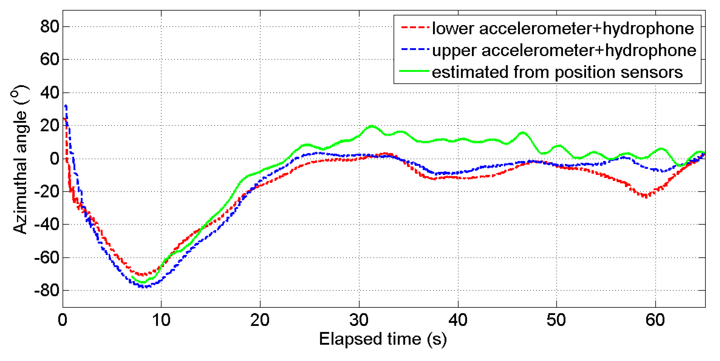
3. Results and Discussion

As already mentioned two azimuth estimates were obtained with DAVS using Equation (1), see reference [3] for details on the signal processing. For this dataset the signals were filtered in the frequency range of the chirp signal content and the estimators were computed in the time domain with an unweighted moving average filter. The azimuth estimate from the non-acoustic data was obtained from the positional information of the AUV, as mentioned in Section 2, which was updated every 0.1 s. To compare with the acoustic estimates, the non-acoustic azimuth estimate was smoothed using a third order Savitzky-Golay filter.
Figure 5 shows the two acoustic azimuth estimates (blue and red curves) superimposed with the estimated angle as derived from the AUV track (green curve). One estimate is computed by combining the upper accelerometer and the hydrophone signals (blue curve) and the other estimate is obtained by combining the lower accelerometer with the same hydrophone signals (red curve). The two estimates show the same trend, the discrepancy between them is attributed to the AUV roll and pitch during sailing, the curves shown here were not corrected for those. Comparing the blue and red curves with the estimated angle from the track (green line) we observe the same trends but for the straight part of the trajectory there is an offset. It may be partially attributed to timing errors in positional information and it is subject to ongoing work.
This paper presented results from an ongoing prototype development of a Dual Accelerometer Vector Sensor. The first results indicated that the device built was successful and it is performing according to expectations, i.e., although the three sensor components are moulded in the same encapsulation material they are sufficiently acoustically decoupled to give a pair of independent measurements. A relatively simple algorithm was sufficient to obtain good azimuth estimation of a sound source. Full performance characterisation and further algorithm development are taking place within the activities of the WiMUST project. The device will be tested in a geophysical survey scenario in November 2016.

Acknowledgments

This work has received funding from the European Union’s Horizon 2020 research and innovation programme under grant agreement No. 645141 (WiMUST project).The authors are grateful to the DSOR Lab personnel of IST-ID for organising the trial.

Conflicts of Interest

The authors declare no conflicts of interst.

Abbreviations

The following abbreviations are used in this manuscript:
AUVAutonomous Underwater Vehicles
DAVSDual Accelerometer Vector Sensor
DSORDynamical Systems and Ocean Robotics Lab
DOADirection Of Arrival
EUEuropean Union
GPSGlobal Positioning System
IST IDInstituto Superior Técnico - Investigação e Desenvolvimento
WiMUSTWidely scalable Mobile Underwater Sonar Technology

References

  1. Felisberto, P.; Santos, P.; Maslov, D.; Jesus, S. Combining pressure and particle velocity sensors for seismic processing. In Proceedings of the Oceans 2016 MTS/IEEE/OES, Monterey, CA, USA, 19–23 September 2016. [Google Scholar]
  2. Nichols, B.; Sabra, K.G. Cross-coherent vector sensor processing for spatially distributed glider networks. J. Acoust. Soc. Am. 2015, 23, EL329–EL335. [Google Scholar] [CrossRef] [PubMed]
  3. Felisberto, P.; Santos, P.; Jesus, S.M. Traking source azimuth using a single vector sensor. In Proceedings of the 4th International Conference on Sensor Technologies and Applications, Venice, Italy, 18–25 July 2010; pp. 416–421. [Google Scholar]
  4. He, J.; Liu, Z. Two-dimensional direction finding of acoustic sources by a vector sensor array using the propagator method. Signal Process. 2008, 88, 2492–2499. [Google Scholar] [CrossRef]
  5. Krishna, K.M.; Anand, G.V. Narrowband detection of acoustic source in shallow ocean using vector sensor array. In Proceedings of the Oceans 2009 MTS/IEEE, Biloxi, USA, 26–29 October 2009; pp. 1–8. [Google Scholar]
  6. Hari, V.N.; Anand, G.V.; Premkumar, A.B.; Madhukumar, A.S. Underwater signal detection in partially known ocean using short acoustic vector sensor array. In Proceedings of the Oceans 2011 IEEE/OES, Santander, Spain, 6–9 June 2011; pp. 1–9. [Google Scholar]
  7. Abdi, A.; Guo, H.; Sutthiwan, P. A new vector sensor receiver for underwater acoustic communication. In Proceedings of the MTS/IEEE Oceans, Vancouver, Canada, 29 September–4 October 2007; pp. 1–10. [Google Scholar]
  8. Song, A.; Badiey, M.; Hursky, P.; Abdi, A. Time reversal receivers for underwater acoustic communication using vector sensors. In Proceedings of the OCEANS 2008, Quebec, Canada, 15–18 September 2008; pp. 1–10. [Google Scholar]
  9. Peng, H.; Li, F. Geoacoustic Inversion based on a Vector Hydrophone Array. Chin. Phys. Lett. 2007, 24, 1980–1997. [Google Scholar]
  10. Santos, P.; Rodríguez, O.C.; Felisberto, P.; Jesus, S.M. Seabed geoacoustic Characterization with a Vector Sensor Array. J. Acoust. Soc. Am. 2010, 128, 2652–2663. [Google Scholar] [CrossRef]
  11. Barr, F.J.; Sanders, J.I. Attenuation of water-column reverberations using pressure and velocity detectors in a water-bottom cable. SEG Technical Program Expanded Abstracts. 1989; 653–656. [Google Scholar]
  12. Widmaier, M.; Fromyr, E.; Dirks, V. Dual-sensor towed streamer: From concept to fleet-wide technology platform. First Break 2015, 33, 83–89. [Google Scholar] [CrossRef]
  13. Al-Khatib, H.; Antonelli, G.; Caffaz, A.; Caiti, A.; Casalino, G.; de Jong, I.B.; Duarte, H.; Indiveri, G.; Jesus, S.; Kebkal, K.; et al. Navigation, guidance and control of underwater vehicles within the widely scalable mobile underwater sonar technology project: An overview. IFAC-PapersOnLine 2015, 48, 189–193. [Google Scholar] [CrossRef]
Figure 1. (a) Photo of DAVS and (b) exploded view of DAVS in 3D solid modelling, showing the Delrin container (white half tube), the acoustically active part (dark yellow), the two accelerometers (gray blocks), the hydrophone (yellow cylinder), the threaded caps (pink), the electronics (dark green block) and the battery pack (light green).
Proceedings 01 00033 g001
Figure 2. DAVS electronic overview: The hydrophone and the two accelerometer signals are acquired on the multi-channel acquisition board, 7 channels in total. The micro-controller receives data from multi-channel acquisition board and stores it in the SD card. Non acoustic sensors give the roll, pitch and heading of the device. Power can be obtained from internal batteries or from external source through a power cable.
Proceedings 01 00033 g002
Figure 3. (a) Photo of the red MEDUSA as operated in this trial and (b) turned upside down position with DAVS attached to it.
Proceedings 01 00033 g003
Figure 4. Sailed track of the AUV towards the source (black asterisk). The black dot indicates the starting point and the arrow the end point for the estimation. The illustration on the top right corner of the figure shows the sensor coordinate system with respect to the track.
Proceedings 01 00033 g004
Figure 5. Estimation of sound azimuth direction of the sound relative to AUV sailing from the track shown in Figure 4, as computed from the lower (red curve) and the upper (blue curve) accelerometer. The green line gives the source azimuth estimate as derived from the AUV positional sensors starting from the point of the track indicated with the green dot in Figure 4.
Proceedings 01 00033 g005
Table 1. DAVS specifications.
CharacteristicDescription
Descriptionvector sensor with autonomous acquisition and power system system,
optional power and data cable
Autonomy20 h operation with 20 V-3100 mAh battery
Bandwidth0.1 kHz–4 kHz
Receiver elements2× accelerometers and 1 Hydrophone
Accelerometers2× PCB 356A17 accelerometers, nominal sensitivity 500 mV/g
Hydrophonecylindrical PZT element, nominal sensitivity −195 dB re μ Pa/V
A/D converter24 bits Sigma Delta, simultaneous sampling at 10,547 sps or 52,734 sps
Storage capacity128 GB microSD card
Time synchroDevice or host RTC when streaming, accuracy 1 s/month
Motion sensors9 axis DoF MEMS with tri-axial accelerometer, magnetometer and gyro
Data transferEthernet connection
Container dimensionsLength: 525 mm, Diameter 65 mm
Device weight1.4 kg in air and neutral in water
Maximum deployment depth100 m
Modes of operationOn batteries or power cable connection to a 24 V DC
Publisher’s Note: MDPI stays neutral with regard to jurisdictional claims in published maps and institutional affiliations.

