Sensing of the Engine Cylinder Valves Motion †


1
Faculty of Automotive Engineering, Ostfalia University of Applied Sciences, Kleiststr. 14-16, D-38440 Wolfsburg, Germany
2
Institute of Product and Process Innovation, Leuphana University of Lueneburg, Volgershall 1, D-21339 Lueneburg, Germany
*
Author to whom correspondence should be addressed.
†
Presented at the 3rd International Electronic Conference on Sensors and Applications, 15–30 November 2016; Available online: https://sciforum.net/conference/ecsa-3.
Proceedings 2017, 1(2), 26; https://doi.org/10.3390/ecsa-3-E013
Published: 15 November 2016
(This article belongs to the Proceedings of Proceedings of the 3rd International Electronic Conference on Sensors and Applications, 15–30 November 2016; Available online: https://sciforum.net/conference/ecsa-3.)
Abstract
:This paper deals with all required parts to set up the full variable valve train (FVVT) system to be used in intake and exhaust valves of combustion engines from the electrical/electronic point of view. This includes the displacement and pressure sensors that are needed to conduct research on the fully variable valve train while in operation and the electronic auxiliaries such as the amplifier for the piezo actuator, the dSPACE control system and the used function generator. In particular, the use of displacement transducers for all relevant pistons and stems is crucial for the FVVT system control. As only the piezo actuator is equipped with a displacement sensor, the remaining sensors still need to be chosen. Within the previous FVVT system two different displacement sensors have been used on the engine valve stem. Three displacement sensors and one pressure sensor are implemented into the mechanical core of the system (consisting of lever transmission, control unit, servo valve and engine valve body), which is driven by the piezo actuator and supplied with hydraulic pressure by a pump, that requires a 230 V power supply and a tank, which the hydraulic fluid can return to. While the pressure sensor monitors the hydraulic pressure within the lever transmission, displacement sensors need to be chosen to monitor the motion of the (1) control piston in the control unit; (2) servo piston within the servo valve; (3) engine valves. Measured results are presented.
1. Introduction
Since the exhaust emissions legislation for motor vehicles with combustion engines is complicating the manufacturing of environmental yet powerful engines more than ever, automobile manufacturers have approached this challenge by means of downsizing, hybridization of combustion and electric engines and variable valve opening times. In these cases conventional, mechanical valve trains are still used. The subject of this paper is the development of a mechatronic control unit as replacement for the camshaft driven valve train of common combustion engines. The system’s aim is a contribution to the progression of the development of modern combustion engines satisfying current demands in terms of economy and efficiency. The problem of the choice of the sensors is one of the most important ones.
2. Peripheral Electric and Electronic Devices
This section introduces all required parts to set up the redesigned FVVT system from the electrical/electronic point of view. This includes the displacement and pressure sensors that are needed to conduct research on the fully variable valve train while in operation and the electronic auxiliaries such as the amplifier for the piezo actuator, the dSPACE control system and the used function generator.
2.1. Block Diagram of the Redesigned FVVT Sytem
A block diagram of all required FVVT system components is illustrated in Figure 1. The abbreviations can be understood as follows:
- AMP = piezo amplifier
- FG = function generator
- LT = lever transmission
- CU = control unit
- SV = servo valve
- EV = engine valve body
A terminal strip is powered by a 12 V power supply and supplies voltage to the piezo amplifier, function generator, all external sensors and the MicroAutoBox, which is the control unit used within this project. The function generator connects to the “Control In” of the piezo ampflifier, providing the signal sent to the actuator. The piezo is powered directly by the amplifier and uses a displacement and temperature monitoring sensor that also connects to the amplifier. From here, the position signal output connects to the input of an impedance converter using a modified BNC (BNC = Bayonet Neill-Concelman Connector) cable. The converter is used to adjust the voltage range of this signal so it can be read by the MicroAutoBox and is powered by a Siemens PLC 24 V power supply. The output of the impedance converter is designed as a BNC connection. A BNC cable connects from the output “SGPIEZO” of the converter board directly to the BNC input box that is connected to the MicroAutoBox.
Three displacement sensors and one pressure sensor are implemented into the mechanical core of the system (consisting of LT, CU, SV and EV), which is driven by the piezo actuator and supplied with hydraulic pressure by a pump (compare broken line in Figure 1), that requires a 230 V power supply and a tank, which the hydraulic fluid can return to. While the pressure sensor monitors the hydraulic pressure within the lever transmission, displacement sensors need to be chosen to monitor the motion of the
- control piston in the control unit
- servo piston within the servo valve
- engine valves
The cables of the three displacement sensors and the pressure transducer have been built in such a way as to enable a connection to the terminal strip for the power supply while the sensor signal wires connect to the input box of the MicroAutoBox using a BNC connector. An Ethernet cable is used to connect the MicroAutoBox to the Lenovo R60 research laptop. The actual sensors chosen for this project and the main characteristics of the electronic core components of the redesigned FVVT system will be explained in the following subsections.
2.2. Displacement Sensors
The use of displacement transducers for all relevant pistons and stems is crucial for the FVVT system control. As only the piezo actuator is equipped with a displacement sensor, the remaining sensors still need to be chosen. Within the previous FVVT system two different displacement sensors have been used on the engine valve stem. Subsequently, these will be introduced and one of them will be chosen for this project.
2.2.1. Sensitec GLM7xxASB-Ax
The functional principle of the GLM700 family sensors from the German sensor manufacturer Sensitec is based on a magneto-resistive measurement. This includes a ferromagnetic rack featuring teeth with a fixed distance to one another and a sensor element with a magnet being mounted perpendicularly to the rack, as seen in Figure 2.
The magneto-resistive effect was discovered around 150 years ago and has been used in sensors for more than 30 years already. The physical principle of the sensor is based on a change in electrical sensor resistance caused by a magnetic field. The GLM700 uses a “Giant MagnetoResistive” (GMR) tooth sensor with an integrated bias magnet. This effect was discovered by Fert and Grünberg in 1988, who received the Nobel Prize for Physics in the year 2007. This effect can be seen in systems consisting of layers of at least two ferromagnetic materials with a single non-magnetic metallic layer in between. The direction of magnetization is the determining factor regarding the sensor resistance. If the layers are magnetized non-parallel, the resistance is up to 50% higher compared to parallel magnetization, that is why this effect is called “giant” [2]. The research of Fert and Grünberg proves that the reason for the increased change in resistance can be explained by one of the ferromagnetic layers influencing the dispersion of electron orientation in the other ferromagnetic layer when those two layers are magnetized antiparallel. This makes it harder for the electrons to pass through the influenced ferromagnetic layer and hence it results in higher electrical resistance.The direction of current is not decisive for the change in resistance. The properties of a GMR sensor can be changed depending on the number of layers and their direction of magnetization. By this the sensor can be made suitable for specific applications and measurement requirements [2]. As the toothed rack is moved along the sensor element a change of the magnetic field occurs, depending if a tooth or a gap of the rack is next to the sensor element. This influences the magnetic field and results in a changed voltage signal of the sensor that can be processed and used for a displacement measurement. Figure 3 shows the GLM700 sensor application used for the measurement of the engine valve travel within the previous FVVT system.
The sensor element and magnet are integrated into the valve stem guide in this application. The corresponding tooth structure is included directly into the valve stem, replacing the toothed rack shown in the schematic Figure 2. The GLM700 sensor works non-contacting and thus is wearless in operation which is a big advantage. Dust and oil on tooth structure and/or sensor have no influence on the measurement. High repeatability makes the sensor suitable for precise measurements. The high dynamic performance and ability to measure under the conditions of extreme speeds and accelerations make the sensor very eligible for the FVVT system [1]. As it is very small it features very good packaging properties. On the other hand, it is extremly expensive compared to other sensor applications and it is very complex to install the sensor element into the valve stem guide.
2.2.2. Gefran PY2C25
The PY2 series sensors are rectilinear displacement transducers that are based on a magnetostrictive principle. According to Deng et al. (2013) magnetostriction in general is a “coupling process between magnetic energy and elastic energy in ferromagnetic materials with high magnetostrictive coefficient” [3]. The way in which this effect can be used in a sensor will be explained subsequently. For better understanding Figure 4 shows the setup of a magnetostrictive displacement sensor.
For the first time magnetostriction was used for displacement measurement applications was in 1970 The ferromagnetic waveguide as measuring element is the core component of the transducer. A mobile position magnet, mounted to the moving part whose position is meant to be measured, induces a longitudinal magnetic field within the waveguide. While a current pulse is sent through the sensor, a second magnetic field is being induced, this time radially around the waveguide. As soon as both magnetic fields meet and interact at the point of measurement, a torsion pulse is produced which travels as structure-borne sound wave through the waveguide at ultrasonic speed. When this pulse reaches the signal processing (torsion pulse converter) that is integrated in the sensor head, the position of the moving part is being precisely determined by measuring the time elapsed between the dispatch of the current pulse and the arrival of the torsion pulse. Hence the sensor principle is based on a time-of-flight measurement [4]. The actual Gefran PY2 series sensor as used within the previous FVVT system is shown in Figure 5.
The sensor end can easily be connected to any rod or stem whose position needs to be measured within this project. The return spring acts as an aid to return the control piston in the control unit when the FVVT system is brought back into its initial position. A further advantage is that this sensor also works on a frictionless, magneto-mechanical basis making it wearless with no need to recalibrate the sensor. The sensor features infinite resolution has a total length of 138 mm. The sensor is far more disadvantageous in terms of packaging, compared with the Sensitec GLM700 sensor. However, this sensor is offered at significantly reduced cost compared to the Sensitec sensor. The sensor is suitable for measurements of velocities up to 10 m/s. With the values shown within the calculations of this research project, 3.92 ms are available to fulfill the maximum servo piston translation of 10 mm at maximum engine speed. This results in a maximum servo piston velocity of 2.55 m/s, which is around 25% of the maximal value, making the sensor suitable for this measurement application.
2.2.3. Cost-Benefit Analysis
As shown in Table 1 a cost-benefit analysis will be conducted to choose the type of displacement transducer that will be used within this project.
For the analysis, all criteria relevant for the sensor selection are compared, whilst a weighting indicates the relevance of each criterion. In columns “FxW” the fulfillment of these criteria (1 lowest to 10 highest) is evaluated by multiplying it with a specific weighting.
The Sensitec transducer does not feature limitations regarding the velocity and acceleration conditions within which it can measure the displacement, resulting in excellent dynamic performance. However, as calculated above, the FVVT system will not reach velocities that exceed the Gefran transducer’s range. Even though the Sensitec transducer offers the advantage regarding dimensions and packaging, the complicated installation of the sensor element and the high cost result in a total fulfillment reduced by 27% compared to the Gefran sensor. Thus, the Gefran PY2C25 displacement transducer will be used for measuring the positions of the control piston in the control unit, the servo piston within the servo valve and at least one of the two engine valves that move simultaneously, solving another of the sub-objectives of this research.
2.3. Pressure Transducer
The transducer type PTDVB1001B1C1 by the manufacturer Parker Hannifin has been used for monitoring the pressure in the lever transmission within the previous FVVT system. This sensor will also be used for the indirectly controlled FVVT system as it proved to be suitable for this application. The pressure needs to be monitored to ensure that it neither exceeds its designated maximum value nor drops too low due to a leak or void formation, affecting the FVVT system control.
The sensor thread fits into an adapter that will be fitted to the control unit housing. A drill 1 mm in diameter leads from the adapter into the lever transmission, enabling the measurement of the hydraulic pressure.
The filtration transducer uses a stainless steel element, coated with alloy and insulation materials, that is in contact with the hydraulic transmitting medium. The transducer can determine pressures up to 100 bar and uses ASIC (Application Specific Integrated Circuit) programmable software. The maximum overload pressure is 250 bar. The full system pressure of 150 bar will not in any case be applied to the lever transmission.
2.4. Piezo Amplifier
An energy recovery power amplifier type HVPZT E-482 will be used to supply the required voltage to the piezo actuator. It is from the manufacturer PI, the same company that delivered the piezo actuator for this project. This amplifier has been designed especially for the dynamic analogue operation of piezo actuators with high electrical capacitance and features an output voltage range of 0 to 1050 V. The input voltage is 0 to 10 V which means the use of an external high voltage power supply is not necessary. The DC (direct current) offset can be configured with the aid of a 10-turn potentiometer, adding 0 to ±10 V to the input voltage. According to PI the energy recovery system allows the amplifier to save up to energy using switched control. Pulse width modulation (PWM) of the piezo output voltage is being used and during discharge of the actuator, the energy partly is being returned into a capacitor storage. This energy can be utilized for the next charging process of the piezo. Thus the amplifier features lower temperatures and provides improved stability. For this project the optional E-509 PZT-Servo Controller has been added. This enables closed-loop control, including a position feedback sensor. According to the manufacturer, this allows for positioning accuracy and repeatability in the nanometre range and even below. This is very important for this project as the control of the FVVT system has to rely on the effectively used travel range of the piezo of = 120 × m. Moreover, the amplifier has an included temperature sensor. Piezo and this sensor are connected to the amplifier by LEMO sockets (push-pull connectors by the Swiss company LEMO S.A.). The temperature sensor deactivates the piezo output voltage when the actuator reaches a temperature of °C. As the operating temperature range is 5 to °C with a loss effect of around at over °C this measure is helpful to protect the actuator [6]. To ensure that the piezo reaches its full displacement under any circumstances and never overheats, its housing will be connected to compressed air in order to enable a convective cooling of the stack.
2.5. Development Control System and Some Measurements
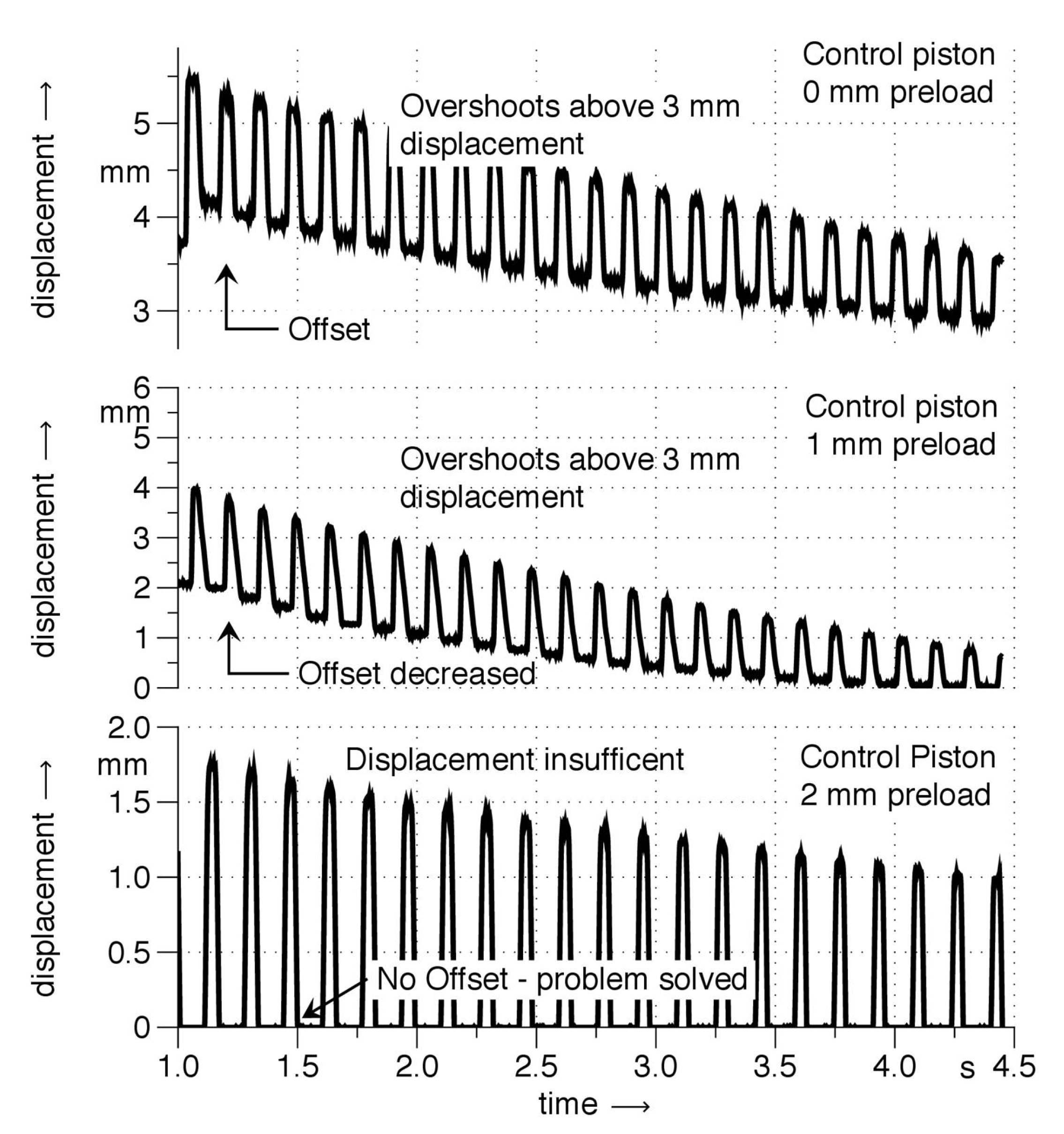
The MicroAutoBox type 1401/1501 from dSPACE that already has been part of the previous FVVT setup, will be used as control system. It is needed for communication purposes between the displacement and pressure transducers and the corresponding ControlDesk software, also provided by dSPACE. The MicroAutoBox works like an engine control unit (ECU) with no user intervention necessaty. The box is suitable for many different applications like x-by-wire or powertrain control. An external power supply is necessary to run the MicroAutoBox. Alongside the standard automotive I/O (Input/Output), an FPGA (Field Programmable Gate Array) (integrated circuit that can be configured by the user) is integrated into the MicroAutoBox. The FPGA can be configured in a Simulink environment. A laptop can easily be connected to the MicroAutoBox enabling application download, parameterization of models and the analysis of data using Ethernet. A flight recorder is integrated into the box for long-term data logging [7]. An experiment with the lever transmission, after implementation of the afore-mentioned measures showed that even though the control piston reciprocates, without an increased preload it does not reach its initial position, which the return spring should return it to. The results of an experimental approach with different return spring preloads can be seen in Figure 6. The pressure in the lever transmission was set to 4 MPa for this experiment, the piezo actuator operated with a sine wave showing a frequency of 7 Hz.
References
- Sensitec. Products, Length-And-Path, Details about the Technical Principles of the Length and Position Measurement. 2014. Available online: http://www.sensitec.com/ (accessed on 27 April 2017).
- Sensitec. Technology, MR Sensor Technology. 2014. Available online: http://www.sensitec.com/ (accessed on 27 April 2017).
- Deng, C.; Kang, Y.; Li, E.; Zhang, Y.; Cheng, J.; Ge, T. A new model of the signal generation mechanism on magnetostrictive position sensor. Measurement 2014, 47, 591–597. [Google Scholar] [CrossRef]
- MTS Sensor Technologie GmbH & Co. KG. Die Temposonics® Positionsmessung—Magnetostriktiv! 2014. Available online: http://www.mtssensor.de/Magnetostriktion.26.0.html (accessed on 27 April 2017).
- Gefran SPA. PY2 Rectilinear Displacement Transducer. 2014. Available online: http://www.gefran.com/en/product_categories/38-\rectilinear-displacement-transducers%28rc1%29/products/73-py2-rectilinear-displacement-transducer#certifications (accessed on 27 April 2017).
- Physik Instrumente (PI). PICA High-Power Piezo Driver/Servo Controller: High Energy Efficiency through Energy Recovery; PDF Catalogue Datasheet; Physik Instrumente GmbH & Co. KG: Karlsruhe/Palmbach, Germany, 2012. [Google Scholar]
- dSPACE. Exklusive Angebote für Hochschulen: dSPACE ACE Kit; Product Brochure; dSPACE Digital Signal Processing and Control Engineering GmbH: Paderborn, Germany, 2014. [Google Scholar]
Figure 1.
Block diagram of the indirectly controlled FVVT system.
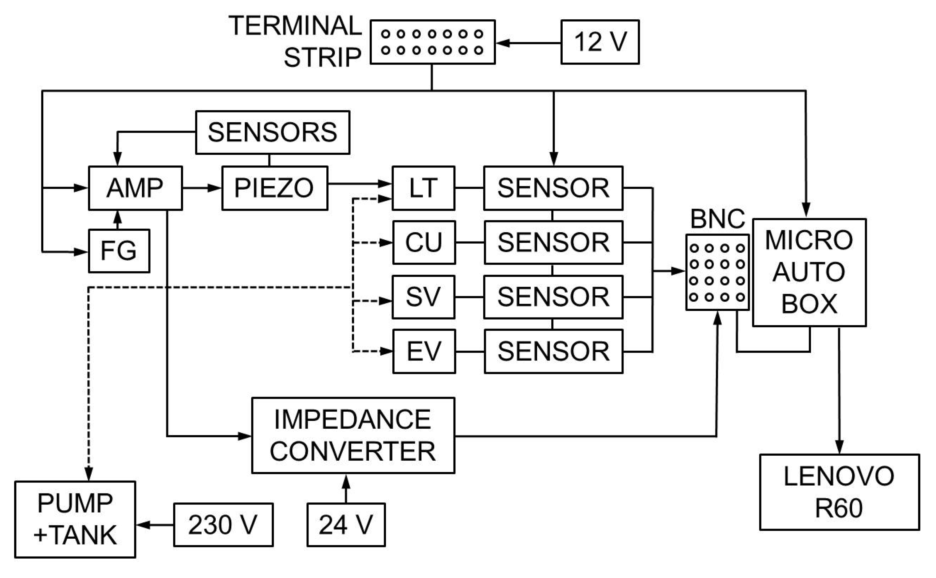
Figure 2.
Sensitec GLM7xxASB-Ax sensor composition [1].
Figure 2.
Sensitec GLM7xxASB-Ax sensor composition [1].
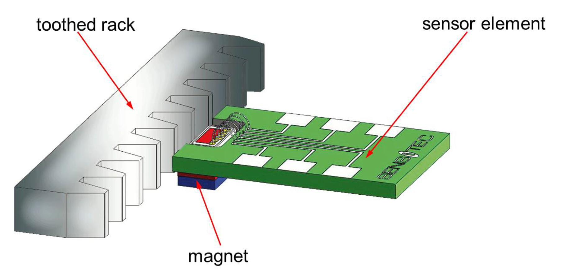
Figure 3.
Sensitec GLM700 FVVT valve travel sensor application.
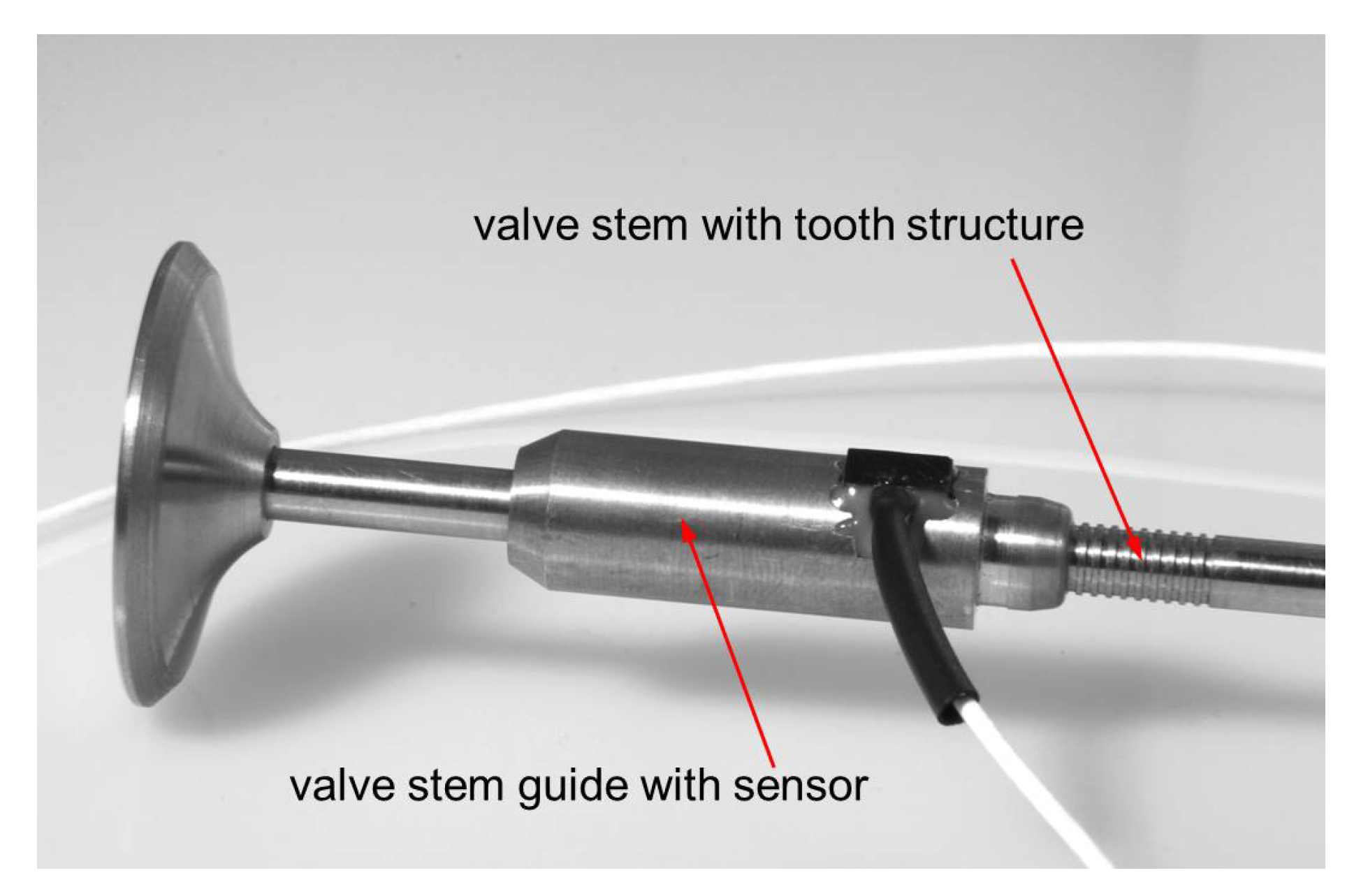
Figure 4.
Principle of magnetostrictive displacement measurement.

Figure 5.
Gefran PY2C25 displacement transducer [5].
Figure 5.
Gefran PY2C25 displacement transducer [5].
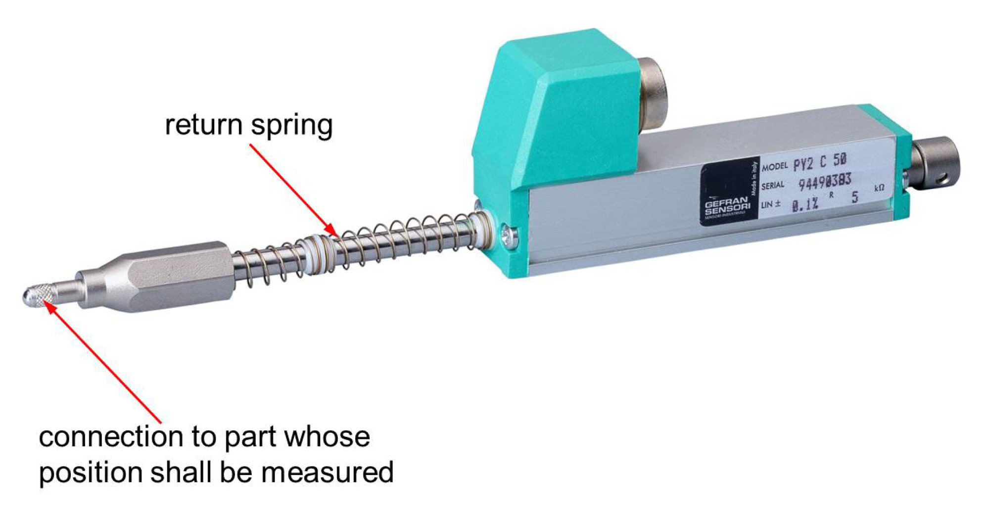
Figure 6.
Control piston displacement in dependency of chosen return spring preload.

Table 1.
Displacement transducer selection.
| Criterion | Weighting | Sensitec GLM700 | Gefran PY2C25 | ||
|---|---|---|---|---|---|
| Fulfillment | FxW | Fulfillment | FxW | ||
| Cost | 4 | 1 | 4 | 8 | 32 |
| Dynamic performance | 3 | 10 | 30 | 8 | 24 |
| Precision | 3 | 10 | 30 | 10 | 30 |
| Sensor wear | 2 | 10 | 20 | 10 | 20 |
| Package | 2 | 10 | 20 | 5 | 10 |
| Installation | 4 | 1 | 4 | 8 | 32 |
| Total | 108 | 148 | |||
| Ranking | 2 | 1 | |||
Publisher’s Note: MDPI stays neutral with regard to jurisdictional claims in published maps and institutional affiliations. |
© 2016 by the authors. Licensee MDPI, Basel, Switzerland. This article is an open access article distributed under the terms and conditions of the Creative Commons Attribution (CC BY) license (https://creativecommons.org/licenses/by/4.0/).
Share and Cite
MDPI and ACS Style
Behre, L.; Mercorelli, P. Sensing of the Engine Cylinder Valves Motion. Proceedings 2017, 1, 26. https://doi.org/10.3390/ecsa-3-E013
AMA Style
Behre L, Mercorelli P. Sensing of the Engine Cylinder Valves Motion. Proceedings. 2017; 1(2):26. https://doi.org/10.3390/ecsa-3-E013
Chicago/Turabian StyleBehre, Leander, and Paolo Mercorelli. 2017. "Sensing of the Engine Cylinder Valves Motion" Proceedings 1, no. 2: 26. https://doi.org/10.3390/ecsa-3-E013