Article

Novel Single-Shot Diagnostics for Electrons from Laser-Plasma Interaction at SPARC_LAB

1
INFN Laboratori Nazionali di Frascati, Via Enrico Fermi 40, 00044 Frascati, Italy
2
Racah Institute of Physics, Hebrew University, 91904 Jerusalem, Israel
3
University of Rome "Tor Vergata", Physics Department, Via della Ricerca Scientifica 1, 00133 Roma, Italy
4
INFN-Roma Tor Vergata, Via della Ricerca Scientifica 1, 00133 Roma, Italy
5
GoLP/ Instituto de Plasmas e Fusão Nuclear, Instituto Superior Técnico, Universidade de Lisboa, Av. Rovisco Pais 1049-001 Lisbon, Portugal
*
Author to whom correspondence should be addressed.
Quantum Beam Sci. 2017, 1(3), 13; https://doi.org/10.3390/qubs1030013
Submission received: 12 August 2017 / Revised: 16 October 2017 / Accepted: 17 October 2017 / Published: 24 October 2017
(This article belongs to the Special Issue Laser-Driven Quantum Beams)

Abstract

:
Nowadays, plasma wakefield acceleration is the most promising acceleration technique for compact and cheap accelerators, needed in several fields, e.g., novel compact light sources for industrial and medical applications. Indeed, the high electric field available in plasma structures (>100 GV/m) allows for accelerating electrons at the GeV energy scale in a few centimeters. Nevertheless, this approach still suffers from shot-to-shot instabilities, mostly related to experimental parameter fluctuations, e.g., laser intensity and plasma density. Therefore, single shot diagnostics are crucial in order to properly understand the acceleration mechanism. In this regard, at the SPARC_LAB Test Facility, we have developed two diagnostic tools to investigate properties of electrons coming from high intensity laser–matter interaction: one relying on Electro Optical Sampling (EOS) for the measurement of the temporal profile of the electric field carried by fast electrons generated by a high intensity laser hitting a solid target, the other one based on Optical Transition Radiation (OTR) for single shot measurements of the transverse emittance. In this work, the basic principles of both diagnostics will be presented as well as the experimental results achieved by means of the SPARC high brightness photo-injector and the high power laser FLAME.

1. Introduction

During the last ten years, huge improvements have been achieved in laser technology, allowing high power systems able to study the interaction between high intensity electromagnetic pulses and matter in a completely new physical regime. Indeed, the possibility to reach power densities larger than 1019 W/cm2 at the femtosecond level has been exploited in many fields of research: astrophysics in the laboratory [1], high energy density experiments [2], electromagnetic wave sources [3,4,5] and novel schemes for particle acceleration [6]. The dream of a table-top accelerator, both for e and p+, has attracted many people working in the plasma field, but, even though compact accelerating systems have been already demonstrated [7,8,9,10], the produced charged particle beams are still affected by shot-by-shot instabilities. Moreover, the physical mechanism is not clear yet, especially concerning the interaction with solid targets for ion acceleration. Therefore, single-shot diagnostics play an important role in order to achieve a better control in laser-plasma experiments.
At the SPARC_LAB Test Facility [11], we have developed two diagnostic tools to investigate the properties of electrons produced by high intensity laser–matter interaction: one relying on Electro Optical Sampling (EOS) has been employed to probe the interaction between the high intensity laser FLAME and a solid target. The EO effect has been used as a bunch length diagnostic for electron beams from laser wakefield acceleration [12,13], but it has been never employed to probe laser–solid target interactions. In particular, a large number of electrons are released from the opposite surface with respect to the laser–target interaction. Those electrons, called fast electrons, are responsible for exit surface ionization and ion/proton acceleration and they have been studied in the past with different approaches [14,15,16,17,18,19]. With this technique, we succeed with measuring for the first time the temporal profile of the electric field carried by fast electrons generated during the interaction with an unprecedented resolution below 100 fs [20,21]. Furthermore, we have investigated the role of the target shape in the fast electron emission in order to optimize the ion and proton acceleration process. In particular, we found out that structured targets allow for getting a boost in the accelerating field [22,23]. The second diagnostic tool we have developed is based on Optical Transition Radiation (OTR) for the single-shot measurement of transverse emittance. Indeed, the OTR angular distribution being sensitive to the beam angular divergence [21,23,24], it is possible to evaluate the correlation term between position and angle by means of a microlens array, therefore allowing for the full retrieval of the e beam transverse emittance. This technique is very promising for future applications in laser wakefield accelerators, allowing for properly tuning the experimental parameters by measuring shot-by-shot the quality of the accelerated beam.
We present in this work an overview of the developed diagnostics, together with experimental results. Particular emphasis is given to the first temporal snapshot of the electric field carried by fast electrons escaping from the interaction between ultra intense laser and solid target. Preliminary tests of the single shot emittance measurements done at the SPARC_LAB photo-injector are also presented and discussed.

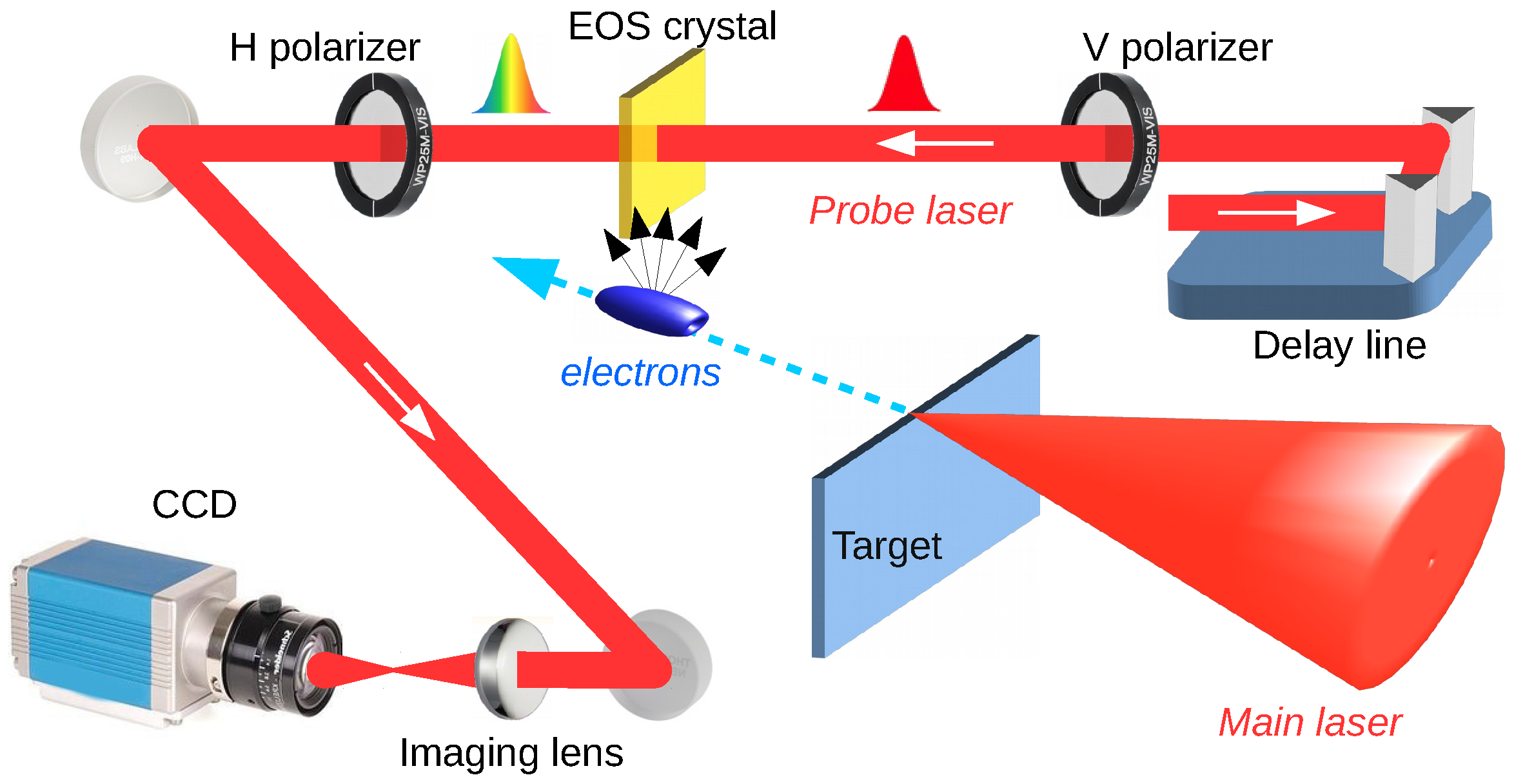
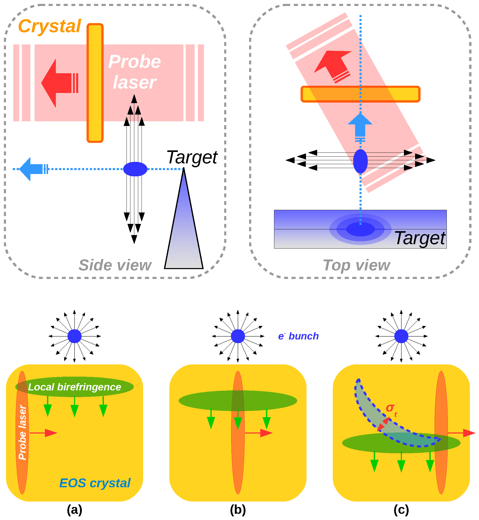
2. EOS Diagnostics for fs Resolution Probing High Intensity Laser–Solid Target Interaction

During the past decade, the interaction of high-intensity lasers with matter has attracted a lot of attention since it allows the production of charged particles and electromagnetic radiation over a large spectrum. In particular, ion acceleration from thin foils irradiated by high-intensity short-pulse lasers is one of the most interesting aspects in this research field since it produces a large number of particles with energies in the multi-MeV range [25,26,27]. Following theoretical models [28,29,30], the process starts when some electrons, directly accelerated by the laser, pass through the target. The majority of them spread out and dissipate energy, while only the fastest component can reach the target rear side [31]. Afterwards, the most energetic electrons escape, leaving an electrostatic potential on target, due to the unbalanced positive charge left on it [32]. Such potential generates an electric field that ionizes and accelerates surface ions in a process called Target Normal Sheath Acceleration (TNSA) [29].
Thus far, only indirect evidence of the escaping electrons has been detected by measuring the radiated electromagnetic pulses [33,34] and magnetic fields [35]. On the other hand, some electron properties, e.g., charge, angular distribution and energy, have been directly measured [36,37,38,39]. Here, we show direct and temporally resolved measurements of the electric field carried by fast electrons. We have used a diagnostics based on Electro-Optical Sampling (EOS) [40], widely exploited in conventional accelerators [41,42], with sub-picosecond resolution. Moreover, the role of the target shape in the fast electron emission has been studied, comparing planar, wedge and tip target geometries hit by a high intensity laser.

2.1. Experimental Setup

The experiment has been performed with the FLAME laser at the SPARC_LAB test-facility [11] using the setup in Figure 1. FLAME consists of a 130 TW Ti:Sapphire laser system delivering 35 fs (FWHM), up to 4 J pulses on target at 800 nm central wavelength and at a 10 Hz repetition rate. The laser beam was focused by a f / 10 off-axis parabolic mirror with focal length f = 1 m. The 1 / e 2 diameter of the laser spot on target was approximately 60 µm, corresponding to a peak intensity of about 1019 W·cm−2. Exploiting such an intense laser pulse, fast electrons are produced by irradiating the tip (about 10 µm thick) of a stainless steel wedged target (see Figure 2a).
The probe laser employed to detect the EO signal (35 fs pulse duration) is directly split from the FLAME laser, ensuring a jitter-free synchronization. The synchronization of the main and probe lasers in coincidence at the EOS crystal is obtained by means of an α -cut beta barium borate (BBO) crystal installed on the ZnTe holder. The time overlap, i.e., our reference time, is then retrieved by measuring the light from the sum frequency generation (SFG). For this purpose, a 3 fs resolution delay-line has been installed on the probe line. Once the reference time is determined, the delay-line is moved in order to synchronize the probe with the emitted electrons and produce a detectable EOS signal.
The EOS diagnostics installed for this experiment relies on a 500 µm-thick ZnTe crystal and employs the spatial decoding technique [43], with the probe laser entering into the crystal at an incidence angle θ i ≈ 28°. In this way, the temporal charge profile of the emitted electrons is spatially imprinted along the transverse profile of the probe laser (see Figure 2b). With d L 6 mm (FWHM) being its transverse spot size, the active time window provided by the EOS is Δ t = ( d L / c ) · sin θ i 10 ps, where c is the vacuum speed of light, with a resolution of about 100 fs.
By measuring the relative delay with respect to the reference time, it is possible to estimate the energy of the emitted electrons [20]. Indeed, EOS being a single-shot device, it can be used as a time of arrival monitor allowing for measuring its time of flight [42,43]. Therefore, this method is able to provide energy measurements resolved in time (see Figure 3). With Δ t T O F being the particle time of flight, we can estimate the bunch velocity as v = d / Δ t T O F and its energy as E = γ m e c 2 , where γ = ( 1 ( v / c ) 2 ) 0.5 is the relativistic Lorentz factor and m e is the electron rest mass. Unlike conventional time-integrated spectrometric techniques, this method is able to provide energy measurements resolved in time. Moreover, the electric field generated by the bunch, inducing the electro-optic effect, is proportional to the overall charge contained in the bunch. Therefore, the fast electron charge can be estimated from the signal intensity.

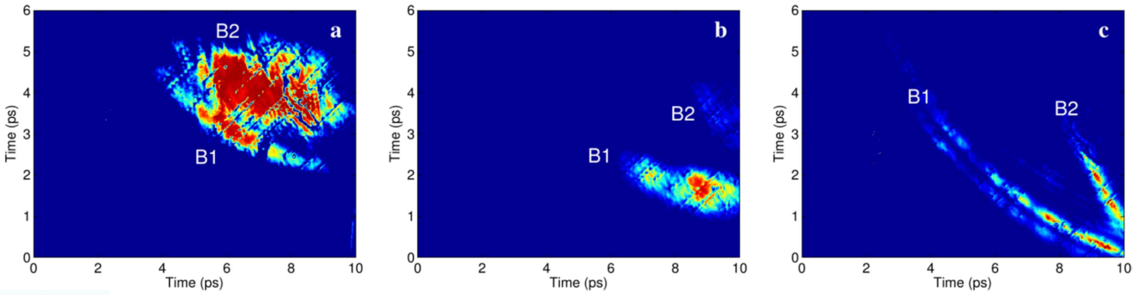
2.2. Experimental Results

Figure 4a reports a typical EOS measurement. The resulting shape is as the one expected in Figure 2b. In order to evaluate the experimental results, we developed a numerical simulation tool [20]. By delaying the probe laser, the position of the EOS signal changes accordingly: the signals shift down because, in the meantime, the induced local birefringence moves far from the path of the travelling electrons (cf. Figure 2b). This is shown in Figure 4c and confirmed by the simulation in Figure 4f. By anticipating the probe laser, the behaviour is the opposite (cf. Figure 4b,e). Moreover, due to our set-up geometry (electrons are moving below the crystal and normally to it while the probe laser propagates laterally from right to left), the local birefringence, induced by the electron bunch's electric field, and the probe laser temporally overlap along the dashed blue region. As a consequence, the EOS signals imaged on the CCD exhibit a curved shape, as predicted in Figure 2b. The mean velocity (and thus the energy) of the moving electrons is evaluated by measuring the delay of the EOS signal centroid with respect to the reference time, as shown in Figure 3. A good agreement between measurements and simulations is obtained by assuming an electron bunch with 2.1 nC charge, 14 MeV energy and about 500 fs duration. The shot-to-shot reproducibility is proved by considering that the structure of the EOS signals in Figure 4a–c remains unaltered while the probe delay is changed. The lack of uniformity in the experimental signals, if compared with the simulated ones, is mainly due to inhomogeneities both on the ZnTe crystal surface and on the transverse profile of the probe laser.
According to the simulated EOS signals, once the mean energy of the travelling bunch is determined, the width of the signal itself is proportional to the bunch duration. Therefore, the charge temporal profile can be obtained by performing a line-out along the time direction depicted in Figure 4a. The result, shown in Figure 5, has been calculated by averaging a series of line-outs along the curved shape of the signal, allowing the retrieval of the peak current, ∼2 kA, carried by the fast electrons. Due to the spatial encoding setup, the time axis is retrieved by calibrating the CCD pixels as Δ t p i x e l = ( Δ x p i x e l / c ) · sin θ i 15 fs, where Δ x p i x e l is the pixel (physical) size.
Once the diagnostic has been calibrated, we studied the influence of target geometry on fast electron properties. In the case of a planar foil target, the resulting snapshot in Figure 6a,d shows the presence of a first emitted bunch with approximately 1.2 nC charge and 7 MeV energy followed by a second broadened structure carrying a larger number of particles (about 3 nC). For the wedged target, the snapshot in Figure 6b,e shows a similar structure: the first bunch now carries a larger amount of electrons (2 nC) at the same energy while the charge in the second bunch is strongly reduced to 0.3 nC. Electron bunches coming from the tip target are shown in Figure 6c,f. In this case, the interaction with the laser produced a much larger number of electrons (about 7 nC) at higher energies (about 12 MeV). These results provide a direct evidence of charge and energy boost when using sharp tips. Therefore, thanks to the sub-picosecond resolution available with such a diagnostic, a consequent field enhancement for ion and proton acceleration has been measured. The laser pulse field is enhanced close to the tip, being able to extract more electrons from it, if compared to conventional planar targets.

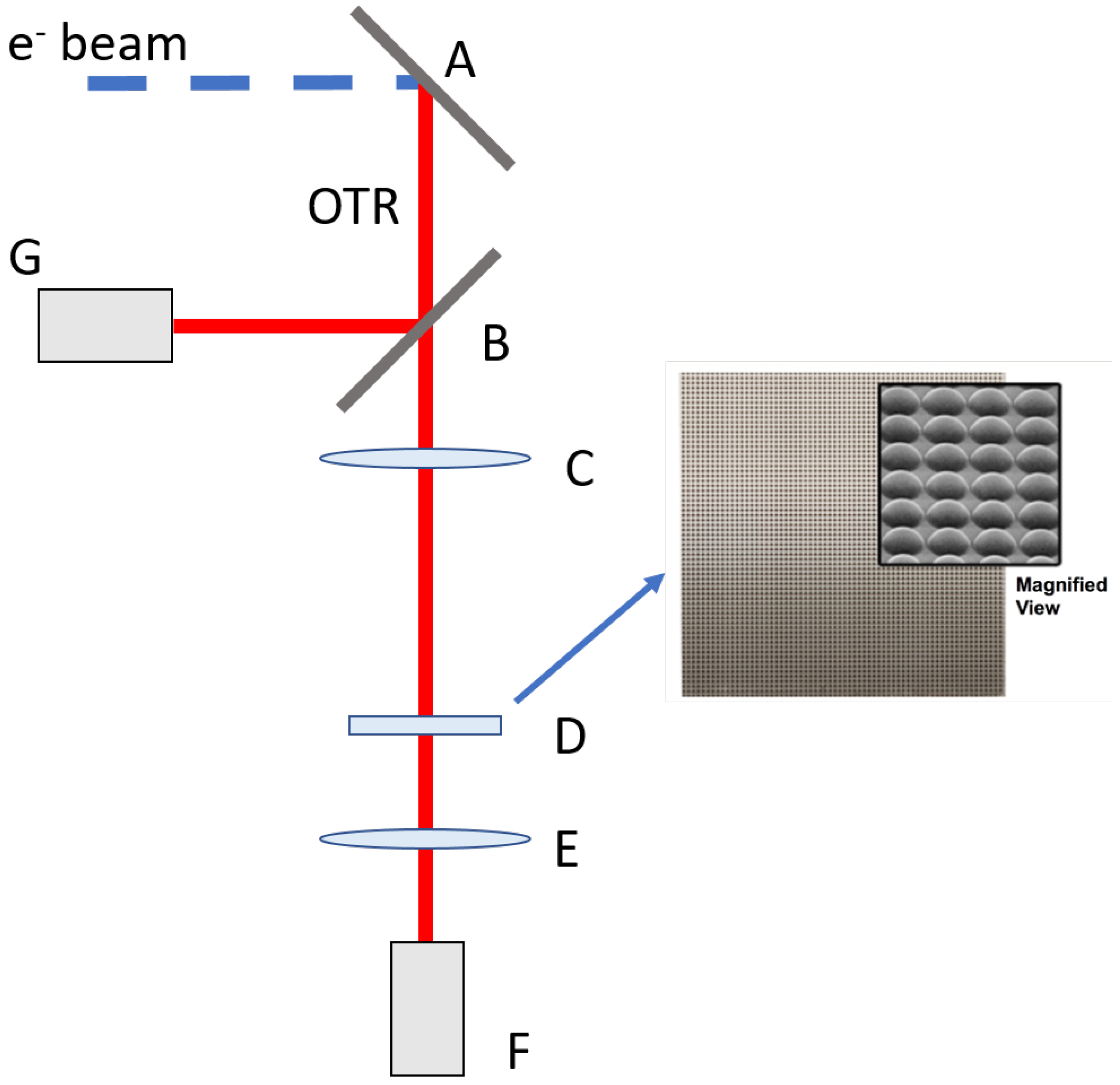
3. Correlation Term Reconstruction for Single-Shot Emittance Measurements through Incoherent OTR

Plasma-based accelerators have been strongly studied in the last ten years due to the large accelerating gradient achievable in mm-scale plasma structures. Even though plasma-based acceleration has been widely demonstrated [7,8,9,10], the accelerated e beams are still characterized by a large energy spread, around 10%, and shot-to-shot instabilities. These issues prevent the use of conventional, multi-shot diagnostics for the emittance measurements, such as the quadrupole scan technique [44,45].
Optical Transition Radiation (OTR) is emitted when a charged particle crosses the boundary between two media with different refractive indices [46]. This radiation is usually used in accelerator facilities to measure the beam transverse size and divergence [47,48,49,50]. Indeed, in the ultra-relativistic approximation and in the far field, the intensity of the angular distribution for a single particle is given by the Ginzburg-Frank formula [46]:
I θ 2 1 γ 2 + θ 2 2 ,
where γ is the relativistic Lorentz factor and θ is the observation angle with respect to the propagation direction. To take into account a finite beam divergence, we consider the convolution of Equation (1) with a Gaussian distribution in angles described by the rms beam divergence σ , resulting in [51]
I 1 2 π σ 2 + ( θ ξ ) 2 1 γ 2 + ( θ ξ ) 2 2 e ξ 2 2 σ 2 d ξ = π μ ν R e Φ ( z ) 1 2 + μ ν z μ 2 ,
where ν = 1 / γ , z = μ ( ν + i θ ) , μ = 1 / 2 π σ , Φ ( z ) = ( 1 e r f ( z ) ) / e z 2 and e r f ( z ) is the complex error function. It is clear from Equation (2) that a finite beam divergence affects mainly the OTR angular distribution central minimum, as shown in Figure 7 for an electron beam with γ = 250 and σ = 1 mrad.
Measuring at the same time the beam transverse spot size and the angular divergence, it is possible to quantify the emittance in a beam waist, where the correlation term between angle and position is zero [52]. Nevertheless, in order to measure the correlated emittance, it is necessary to reconstruct the correlation term as well. Our idea relies on using a microlens array to retrieve the correlation term. Indeed, it allows for correlating the beam divergence with the spatial position, by looking at the OTR angular distribution generated in the focal plane of each microlens, placed in different spatial positions. In this scheme, the resolution is related to the visibility of the central minimum with respect to the peak value of the angular distribution intensity, defined as V = ( I M A X I M I N ) / ( I M A X + I M I N ) . In detail, considering as a minimum threshold for the measurement the 10% visibility, it is possible to retrieve the minimum angular divergence detectable as a function of the beam energy (Figure 8).

Experimental Setup

Figure 9 shows the layout of our experimental setup for single-shot emittance diagnostics. The OTR emitted by electrons hitting a silicon aluminated screen is split into two arms: the reflected radiation from the beam splitter is used for transverse spot size measurement by means of a high quantum efficiency Hamamatsu Orca II camera (Hamamatsu City, Japan), equipped with a Nikon (Minato City, Japan) f = 180 mm focal length F/2.8; the transmitted part passes through a 400 mm focal length achromatic doublet. This lens makes a 1:1 replica of OTR source in its image plane, where the microlens array (10 mm × 10 mm, 300 µm pitch, 18.7 mm focal length plano-convex lenses) is placed. Finally, its focal plane is imaged onto an intensified camera (Hamamatsu Orca IV) by means of a 50 mm focal length achromatic doublet.
The whole setup has been simulated by means of Zemax 2014 [53], an optical and illumination design software, to evaluate any possible aberrations affecting the measurement, with particular attention to the microlens array. For this purpose, the OTR field generated by the single electron [54] has been used through a custom DLL (dynamic-link library). Then, the single contribution has been propagated through all the optical system and the final intensities have been summed up, weighted with a Gaussian distribution to take into account their spatial position. Moreover, the electron beam divergence has been considered by selecting different starting angle for the propagation, depending on the spatial position. In Figure 10, a qualitative comparison between simulation and experimental results is reported. Each illuminated lens produces in its own focal plane the angular distribution related to a specific portion of the incoming OTR radiation. By analyzing the single contribution, it is possible to retrieve the value of the angular spread. The qualitative agreement between simulation and measurement is excellent. We extract from every single contribution the profile and we fit them in order to measure the central minimum (Figure 11). The experiment has been performed with the SPARC_LAB photoinjector [11], using 200 pC bunch charge at 125 MeV. The maximum energy achievable in this run was limited by the use of only two of the three accelerating sections, resulting in a poor angular resolution: the minimum detectable angular divergence was equal to 500 µrad (see Figure 8), while the expected divergence was 250 µrad [24]. Even though we could not measure the emittance, these preliminary results show that it is possible to produce the OTR angular distribution from a different part of the beam image. On the other hand, this scheme is very promising for future applications in both conventional and plasma accelerators.

4. Conclusions

We presented the development of two single-shot diagnostics for electron beams like those generated from ultra intense laser-plasma interactions. One relies on Electro Optical Sampling aiming to measure the longitudinal profile of electric field carried by fast electrons escaping from a solid target hit by a high intensity laser (>1018 W/cm2). The characterization of these electrons can help to better understand the process of ion acceleration occurring in this kind of interaction. As reported in Figure 4, the signals have been well reproduced and electron properties, in terms of charge, current and mean energy, have been retrieved. The main result of this experiment is related to the first temporally resolved measurement of the charge profile of the fast electrons, shown in Figure 5. For our experimental parameters, a charge of about 2.1 nC in 500 fs FWHM has been measured. Moreover, thanks to this diagnostic tool, further studies have been conducted about the possible effects due to different target geometries. In particular, we have compared the behaviour of planar, wedged and tip targets. The results, reported in Figure 6, show the tip target emits faster electrons and with more charge resulting in a stronger electric field. Therefore, it is possible to boost the ion acceleration by using structured targets exploiting the consequently electric field enhancement.
On the other hand, a new scheme for single shot emittance measurements has been proposed. It relies on the characterization of Optical Transition Radiation (OTR) emitted by a charged particle beam when it impinges on a metallic foil, exploiting the effect on the angular distribution due to the beam divergence (Figure 7). In order to measure the emittance correlation term, the idea we are studying is to use a microlens array, analyzing the OTR angular distribution coming from each microlens, placed in a specified position. In this way, by measuring also the transverse spot size (see Figure 9), an emittance measurement is achievable in one shot. This kind of diagnostic represents a very useful tool to fully characterize an electron beam from laser wakefield acceleration despite its typical shot-to-shot instabilities and relative large energy spread. Some preliminary results obtained with the SPARC_LAB photo-injector have been reported. Even though the emittance measurement was not possible because of poor angular resolution, these results show the possibility to measure the OTR angular distribution produced by different parts of the same electron beam. A measurement on a plasma-accelerated electron beam at the FLAME Facility is still under design, with both self-injection and external injection [55,56] schemes. The aim of this experiment, besides testing these diagnostics, is to quantify the emittance growth when the beam leaves the plasma channel by exploiting recent results with betatron radiation measurements [4].

Acknowledgments

This work has been partially supported by the EU Commission in the Seventh Framework Program, Grant Agreement 312453-EuCARD-2 and the Italian Research Minister in the framework of FIRB - Fondo per gli Investimenti della Ricerca di Base, Project n. RBFR12NK5K. The work of one of us (A.Z.) was partially supported by BSF foundation.

Author Contributions

M.P.A., F.B., A.Cu., M.G., R.P., E.S. and A.Z. carried out the EOS experiment and data analysis. R.P., E.C. and A.Ci. contributed to the design study and development of the EOS diagnostics. F.B., A.Cu., M.G., E.S. and A.Z. developed the FLAME target area and the related imaging system. F.B., M.P.A., A.Cu. and M.G. managed the FLAME laser during the experiment. M.B. provided numerical simulations for the laser-target interaction. A.Z. and M.F. planned and managed the project with inputs from all the co-authors. F.B. and A.Ci. delevoped the emittance correlation term reconstruction method and built the experimental setup. F.B. performed Zemax simulations for optical design optimization. F.B., E.C., A.Ci., R.P. and A.Z. wrote the manuscript. All authors extensively discussed the results and reviewed the manuscript.

Conflicts of Interest

The authors declare no conflict of interest.

References

  1. Remington, B.A.; Arnett, D.; Paul, R.; Takabe, H. Modeling astrophysical phenomena in the laboratory with intense lasers. Science 1999, 284, 1488–1493. [Google Scholar] [CrossRef]
  2. Roth, M.; Cowan, T.; Key, M.; Hatchett, S.; Brown, C.; Fountain, W.; Johnson, J.; Pennington, D.; Snavely, R.; Wilks, S.; et al. Fast ignition by intense laser-accelerated proton beams. Phys. Rev. Lett. 2001, 86, 436. [Google Scholar] [CrossRef] [PubMed]
  3. Rousse, A.; Phuoc, K.T.; Shah, R.; Pukhov, A.; Lefebvre, E.; Malka, V.; Kiselev, S.; Burgy, F.; Rousseau, J.P.; Umstadter, D.; et al. Production of a keV X-ray beam from synchrotron radiation in relativistic laser-plasma interaction. Phys. Rev. Lett. 2004, 93, 135005. [Google Scholar] [CrossRef] [PubMed]
  4. Curcio, A.; Anania, M.; Bisesto, F.; Chiadroni, E.; Cianchi, A.; Ferrario, M.; Filippi, F.; Giulietti, D.; Marocchino, A.; Petrarca, M.; et al. Trace-space reconstruction of low-emittance electron beams through betatron radiation in laser-plasma accelerators. Phys. Rev. Accel. Beams 2017, 20, 012801. [Google Scholar] [CrossRef]
  5. Curcio, A.; Anania, M.; Bisesto, F.; Faenov, A.; Ferrario, M.; Galletti, M.; Giulietti, D.; Kodama, R.; Petrarca, M.; Pikuz, T.; et al. Characterization of X-ray radiation from solid Sn target irradiated by femtosecond laser pulses in the presence of air plasma sparks. Laser Part. Beams 2016, 34, 533–538. [Google Scholar] [CrossRef]
  6. Tajima, T.; Dawson, J. Laser electron accelerator. Phys. Rev. Lett. 1979, 43, 267. [Google Scholar] [CrossRef]
  7. Geddes, C.; Toth, C.; Van Tilborg, J.; Esarey, E.; Schroeder, C.; Bruhwiler, D.; Nieter, C.; Cary, J.; Leemans, W. High-quality electron beams from a laser wakefield accelerator using plasma-channel guiding. Nature 2004, 431, 538–541. [Google Scholar] [CrossRef] [PubMed]
  8. Leemans, W.; Nagler, B.; Gonsalves, A.; Tóth, C.; Nakamura, K.; Geddes, C.; Esarey, E.; Schroeder, C.; Hooker, S. GeV electron beams from a centimetre-scale accelerator. Nat. Phys. 2006, 2, 696–699. [Google Scholar] [CrossRef]
  9. Maksimchuk, A.; Gu, S.; Flippo, K.; Umstadter, D.; Bychenkov, V.Y. Forward ion acceleration in thin films driven by a high-intensity laser. Phys. Rev. Lett. 2000, 84, 4108. [Google Scholar] [CrossRef] [PubMed]
  10. Macchi, A.; Borghesi, M.; Passoni, M. Ion acceleration by superintense laser-plasma interaction. Rev. Mod. Phys. 2013, 85, 751. [Google Scholar]
  11. Ferrario, M.; Alesini, D.; Anania, M.; Bacci, A.; Bellaveglia, M.; Bogdanov, O.; Boni, R.; Castellano, M.; Chiadroni, E.; Cianchi, A.; et al. SPARC_LAB present and future. Nucl. Instrum. Methods Phys. Res. Sec. B Beam Interact. Mater. At. 2013, 309, 183–188. [Google Scholar] [CrossRef] [Green Version]
  12. Jamison, S.P.; Shen, J.; MacLeod, A.M.; Gillespie, W.; Jaroszynski, D.A. High-temporal-resolution, single-shot characterization of terahertz pulses. Opt. Lett. 2003, 28, 1710–1712. [Google Scholar] [CrossRef] [PubMed]
  13. Helle, M.; Gordon, D.; Kaganovich, D.; Ting, A. Extending electro-optic detection to ultrashort electron beams. Phys. Rev. Spec. Top.-Accel. Beams 2012, 15, 052801. [Google Scholar] [CrossRef]
  14. Popescu, H.; Baton, S.; Amiranoff, F.; Rousseaux, C.; Le Gloahec, M.R.; Santos, J.; Gremillet, L.; Koenig, M.; Martinolli, E.; Hall, T.; et al. Subfemtosecond, coherent, relativistic, and ballistic electron bunches generated at ω 0 and 2 ω 0 in high intensity laser-matter interaction. Phys. Plasmas 2005, 12, 063106. [Google Scholar] [CrossRef]
  15. Jung, R.; Osterholz, J.; Löwenbrück, K.; Kiselev, S.; Pretzler, G.; Pukhov, A.; Willi, O.; Kar, S.; Borghesi, M.; Nazarov, W.; et al. Study of electron-beam propagation through preionized dense foam plasmas. Phys. Rev. Lett. 2005, 94, 195001. [Google Scholar] [CrossRef] [PubMed]
  16. Santos, J.; Amiranoff, F.; Baton, S.; Gremillet, L.; Koenig, M.; Martinolli, E.; Le Gloahec, M.R.; Rousseaux, C.; Batani, D.; Bernardinello, A.; et al. Fast electron transport in ultraintense laser pulse interaction with solid targets by rear-side self-radiation diagnostics. Phys. Rev. Lett. 2002, 89, 025001. [Google Scholar] [CrossRef] [PubMed]
  17. Santos, J.; Debayle, A.; Nicolaï, P.; Tikhonchuk, V.; Manclossi, M.; Batani, D.; Guemnie-Tafo, A.; Faure, J.; Malka, V.; Honrubia, J. Fast-electron transport and induced heating in aluminum foils. Phys. Plasmas 2007, 14, 103107. [Google Scholar] [CrossRef]
  18. Storm, M.; Solodov, A.; Myatt, J.; Meyerhofer, D.; Stoeckl, C.; Mileham, C.; Betti, R.; Nilson, P.; Sangster, T.; Theobald, W.; et al. High-current, relativistic electron-beam transport in metals and the role of magnetic collimation. Phys. Rev. Lett. 2009, 102, 235004. [Google Scholar] [CrossRef] [PubMed]
  19. Bellei, C.; Nagel, S.; Kar, S.; Henig, A.; Kneip, S.; Palmer, C.; Sävert, A.; Willingale, L.; Carroll, D.; Dromey, B.; et al. Micron-scale fast electron filaments and recirculation determined from rear-side optical emission in high-intensity laser–solid interactions. New J. Phys. 2010, 12, 073016. [Google Scholar] [CrossRef]
  20. Pompili, R.; Anania, M.; Bisesto, F.; Botton, M.; Castellano, M.; Chiadroni, E.; Cianchi, A.; Curcio, A.; Ferrario, M.; Galletti, M.; et al. Sub-picosecond snapshots of fast electrons from high intensity laser-matter interactions. Opt. Express 2016, 24, 29512–29520. [Google Scholar] [CrossRef] [PubMed]
  21. Bisesto, F.; Anania, M.; Chiadroni, E.; Cianchi, A.; Costa, G.; Curcio, A.; Ferrario, M.; Galletti, M.; Pompili, R.; Schleifer, E.; et al. Innovative single-shot diagnostics for electrons accelerated through laser-plasma interaction at FLAME. In Proceedings of the 2017 SPIE Optics + Optoelectronics, Prague, Czech Republic, 24–27 April 2017; International Society for Optics and Photonics: Bellingham, WA, USA, 2017; p. 102400. [Google Scholar]
  22. Pompili, R.; Anania, M.; Bisesto, F.; Botton, M.; Castellano, M.; Chiadroni, E.; Cianchi, A.; Curcio, A.; Ferrario, M.; Galletti, M.; et al. Femtosecond dynamics of energetic electrons in high intensity laser-matter interactions. Sci. Rep. 2016, 6, 35000. [Google Scholar] [CrossRef] [PubMed]
  23. Bisesto, F.; Anania, M.P.; Chiadroni, E.; Cianchi, A.; Curcio, A.; Ferrario, M.; Pompili, R.; Zigler, A. Innovative single-shot diagnostics for electrons from laser wakefield acceleration at FLAME. In Proceedings of the 8th International Particle Accelerator Conference (IPAC’17), Copenhagen, Denmark, 14–19 May 2017; JACoW: Geneva, Switzerland, 2017; pp. 1727–1730. [Google Scholar]
  24. Cianchi, A.; Anania, M.; Bellaveglia, M.; Bisesto, F.; Castellano, M.; Chiadroni, E.; Di Giovenale, D.; Di Pirro, G.; Ferrario, M.; Gatti, G.; et al. Transverse emittance diagnostics for high brightness electron beams. Nucl. Instrum. Methods Phys. Res. Sec. A Accel. Spectrom. Detect. Assoc. Equip. 2017, 865, 63–66. [Google Scholar] [CrossRef]
  25. Clark, E.; Krushelnick, K.; Zepf, M.; Beg, F.; Tatarakis, M.; Machacek, A.; Santala, M.; Watts, I.; Norreys, P.; Dangor, A. Energetic heavy-ion and proton generation from ultraintense laser-plasma interactions with solids. Phys. Rev. Lett. 2000, 85, 1654. [Google Scholar] [CrossRef] [PubMed]
  26. Snavely, R.; Key, M.; Hatchett, S.; Cowan, T.; Roth, M.; Phillips, T.; Stoyer, M.; Henry, E.; Sangster, T.; Singh, M. Intense high-energy proton beams from petawatt-laser irradiation of solids. Phys. Rev. Lett. 2000, 85, 2945. [Google Scholar] [CrossRef] [PubMed]
  27. Mackinnon, A.; Sentoku, Y.; Patel, P.; Price, D.; Hatchett, S.; Key, M.; Andersen, C.; Snavely, R.; Freeman, R. Enhancement of proton acceleration by hot-electron recirculation in thin foils irradiated by ultraintense laser pulses. Phys. Rev. Lett. 2002, 88, 215006. [Google Scholar] [CrossRef] [PubMed]
  28. Dubois, J.L.; Lubrano-Lavaderci, F.; Raffestin, D.; Ribolzi, J.; Gazave, J.; La Fontaine, A.C.; d’Humières, E.; Hulin, S.; Nicolaï, P.; Poyé, A. Target charging in short-pulse-laser-plasma experiments. Phys. Rev. E 2014, 89, 013102. [Google Scholar] [CrossRef] [PubMed]
  29. Wilks, S.; Langdon, A.; Cowan, T.; Roth, M.; Singh, M.; Hatchett, S.; Key, M.; Pennington, D.; MacKinnon, A.; Snavely, R. Energetic proton generation in ultra-intense laser-solid interactions. Phys. Plasmas 2001, 8, 542–549. [Google Scholar] [CrossRef]
  30. Mora, P. Plasma expansion into a vacuum. Phys. Rev. Lett. 2003, 90, 185002. [Google Scholar] [CrossRef] [PubMed]
  31. Singh, P.K.; Cui, Y.; Chatterjee, G.; Adak, A.; Wang, W.; Ahmed, S.; Lad, A.D.; Sheng, Z.; Kumar, G.R. Direct observation of ultrafast surface transport of laser-driven fast electrons in a solid target. Phys. Plasmas 2013, 20, 110701. [Google Scholar] [CrossRef]
  32. Poyé, A.; Hulin, S.; Bailly-Grandvaux, M.; Dubois, J.L.; Ribolzi, J.; Raffestin, D.; Bardon, M.; Lubrano-Lavaderci, F.; D’Humières, E.; Santos, J.J. Physics of giant electromagnetic pulse generation in short-pulse laser experiments. Phys. Rev. E 2015, 91, 043106. [Google Scholar] [CrossRef] [PubMed]
  33. Jäckel, O.; Polz, J.; Pfotenhauer, S.; Schlenvoigt, H.; Schwoerer, H.; Kaluza, M. All-optical measurement of the hot electron sheath driving laser ion acceleration from thin foils. New J. Phys. 2010, 12, 103027. [Google Scholar] [CrossRef]
  34. Nilson, P.; Davies, J.; Theobald, W.; Jaanimagi, P.; Mileham, C.; Jungquist, R.; Stoeckl, C.; Begishev, I.; Solodov, A.; Myatt, J. Time-resolved measurements of hot-electron equilibration dynamics in high-intensity laser interactions with thin-foil solid targets. Phys. Rev. Lett. 2012, 108, 085002. [Google Scholar] [CrossRef] [PubMed]
  35. Sandhu, A.; Dharmadhikari, A.; Rajeev, P.; Kumar, G.R.; Sengupta, S.; Das, A.; Kaw, P. Laser-generated ultrashort multimegagauss magnetic pulses in plasmas. Phys. Rev. Lett. 2002, 89, 225002. [Google Scholar] [CrossRef] [PubMed]
  36. Key, M.; Cable, M.; Cowan, T.; Estabrook, K.; Hammel, B.; Hatchett, S.; Henry, E.; Hinkel, D.; Kilkenny, J.; Koch, J.; et al. Hot electron production and heating by hot electrons in fast ignitor research. Phys. Plasmas 1998, 5, 1966–1972. [Google Scholar] [CrossRef]
  37. Ping, Y.; Shepherd, R.; Lasinski, B.; Tabak, M.; Chen, H.; Chung, H.; Fournier, K.; Hansen, S.; Kemp, A.; Liedahl, D.; et al. Absorption of short laser pulses on solid targets in the ultrarelativistic regime. Phys. Rev. Lett. 2008, 100, 085004. [Google Scholar] [PubMed]
  38. Santala, M.; Zepf, M.; Watts, I.; Beg, F.; Clark, E.; Tatarakis, M.; Krushelnick, K.; Dangor, A.; McCanny, T.; Spencer, I.; et al. Effect of the plasma density scale length on the direction of fast electrons in relativistic laser-solid interactions. Phys. Rev. Lett. 2000, 84, 1459. [Google Scholar] [CrossRef] [PubMed]
  39. Chen, H.; Shepherd, R.; Chung, H.; Kemp, A.; Hansen, S.; Wilks, S.; Ping, Y.; Widmann, K.; Fournier, K.; Dyer, G.; et al. Fast-electron-relaxation measurement for laser-solid interaction at relativistic laser intensities. Phys. Rev. E 2007, 76, 056402. [Google Scholar] [CrossRef] [PubMed]
  40. Wilke, I.; MacLeod, A.M.; Gillespie, W.; Berden, G.; Knippels, G.; Van Der Meer, A. Single-shot electron-beam bunch length measurements. Phys. Rev. Lett. 2002, 88, 124801. [Google Scholar] [CrossRef] [PubMed]
  41. Steffen, B.; Arsov, V.; Berden, G.; Gillespie, W.; Jamison, S.; MacLeod, A.M.; Van Der Meer, A.; Phillips, P.; Schlarb, H.; Schmidt, B. Electro-optic time profile monitors for femtosecond electron bunches at the soft X-ray free-electron laser FLASH. Phys. Rev. Spec. Top.-Accel. Beams 2009, 12, 032802. [Google Scholar] [CrossRef]
  42. Pompili, R.; Anania, M.P.; Bellaveglia, M.; Biagioni, A.; Castorina, G.; Chiadroni, E.; Cianchi, A.; Croia, M.; Giovenale, D.D.; Ferrario, M.; et al. Femtosecond timing-jitter between photo-cathode laser and ultra-short electron bunches by means of hybrid compression. New J. Phys. 2016, 18, 083033. [Google Scholar] [CrossRef]
  43. Cavalieri, A.L.; Fritz, D.; Lee, S.; Bucksbaum, P.; Reis, D.; Rudati, J.; Mills, D.; Fuoss, P.; Stephenson, G.; Kao, C. Clocking femtosecond X-rays. Phys. Rev. Lett. 2005, 94, 114801. [Google Scholar] [CrossRef] [PubMed]
  44. Löhl, F.; Schreiber, S.; Castellano, M.; Di Pirro, G.; Catani, L.; Cianchi, A.; Honkavaara, K. Measurements of the transverse emittance at the FLASH injector at DESY. Phys. Rev. Spec. Top.-Accel. Beams 2006, 9, 092802. [Google Scholar] [CrossRef]
  45. Mostacci, A.; Bellaveglia, M.; Chiadroni, E.; Cianchi, A.; Ferrario, M.; Filippetto, D.; Gatti, G.; Ronsivalle, C. Chromatic effects in quadrupole scan emittance measurements. Phys. Rev. Spec. Top.-Accel. Beams 2012, 15, 082802. [Google Scholar] [CrossRef]
  46. Ter-Mikaelian, M.L. High Energy Electromagnetic Processes in Condensed Media; Wiley: New York, NY, USA, 1972. [Google Scholar]
  47. Rule, D. Transition radiation diagnostics for intense charged particle beams. Nucl. Instrum. Methods Phys. Res. Sec. B Beam Interact. Mater. At. 1987, 24, 901–904. [Google Scholar] [CrossRef]
  48. Castellano, M.; Verzilov, V. Spatial resolution in optical transition radiation beam diagnostics. Phys. Rev. Spec. Top.-Accel. Beams 1998, 1, 062801. [Google Scholar] [CrossRef]
  49. Bosser, J.; Mann, J.; Ferioli, G.; Warts, L. Optical transition radiation proton beam profile monitor. Nucl. Instrum. Methods Phys. Res. Sec. A Accel. Spectrom. Detect. Assoc. Equip. 1985, 238, 45–52. [Google Scholar] [CrossRef]
  50. Wartski, L.; Marcou, J.; Roland, S. Detection of optical transition radiation and its application to beam diagnostics. IEEE Trans. Nucl. Sci. 1973, 20, 544–548. [Google Scholar] [CrossRef]
  51. Chiadroni, E.; Castellano, M.; Cianchi, A.; Honkavaara, K.; Kube, G. Effects of transverse electron beam size on transition radiation angular distribution. Nucl. Instrum. Methods Phys. Res. Sec. A Accel. Spectrom. Detect. Assoc. Equip. 2012, 673, 56–63. [Google Scholar] [CrossRef]
  52. Feldman, R.; Lumpkin, A.; Rule, D.; Fiorito, R. Developments in on-line, electron-beam emittance measurements using optical-transition radiation techniques. Nucl. Instrum. Methods Phys. Res. Sec. A Accel. Spectrom. Detect. Assoc. Equip. 1990, 296, 193–198. [Google Scholar] [CrossRef]
  53. Zemax 13 Optical Design Program User’s Manual; Zemax LLC: Seattle, WA, USA, 2014.
  54. Castellano, M.; Cianchi, A.; Orlandi, G.; Verzilov, V. Effects of diffraction and target finite size on coherent transition radiation spectra in bunch length measurements. Nucl. Instrum. Methods Phys. Res. Sec. A Accel. Spectrom. Detect. Assoc. Equip. 1999, 435, 297–307. [Google Scholar] [CrossRef]
  55. Bisesto, F.; Anania, M.; Bacci, A.; Bellaveglia, M.; Chiadroni, E.; Cianchi, A.; Curcio, A.; Di Giovenale, D.; Di Pirro, G.; Ferrario, M.; et al. Laser-capillary interaction for the EXIN project. Nucl. Instrum. Methods Phys. Res. Sec. A Accel. Spectrom. Detect. Assoc. Equip. 2016, 829, 309–313. [Google Scholar] [CrossRef]
  56. Rossi, A.; Anania, M.; Bacci, A.; Belleveglia, M.; Bisesto, F.; Chiadroni, E.; Cianchi, A.; Curcio, A.; Gallo, A.; Di Giovenale, D.; et al. Stability study for matching in laser driven plasma acceleration. Nucl. Instrum. Methods Phys. Res. Sec. A Accel. Spectrom. Detect. Assoc. Equip. 2016, 829, 67–72. [Google Scholar] [CrossRef]
Figure 1. Setup of the experiment. The FLAME laser is focused onto a metallic target. The EOS diagnostics, based on a ZnTe crystal placed 1 mm downstream from the target, allows for measuring the temporal profile of the emitted electron bunch by means of an ancillary laser beam (probe), directly split from the main laser, probing the local birefringence induced by the electric field [20].
Qubs 01 00013 g001
Figure 2. (Top) The emitted bunch travels normally to the crystal surface and moves below it while the probe laser crosses the crystal with a non-zero incidence angle; (Bottom) Spatial encoding process: (a) the bunch Coulomb field makes the crystal birefringent; (b) while the electric field penetrates into the crystal, the local birefringence shifts downwards; (c) the probe laser crosses the crystal and its polarization is rotated: the resulting signal comes from the blue region, i.e., where the local birefringence and the probe laser temporally overlapped [20].
Qubs 01 00013 g002
Figure 3. Diagnostics calibration for time of flight measurements. Each point corresponds to one delay line step (3 fs). The inset shows a magnification of the first part (higher energies) [20].
Qubs 01 00013 g003
Figure 4. (ac) experimental EOS data obtained by changing the probe laser delay ( Δ t ) with respect to the main laser. For a delay (advance) of the probe laser, the resulting signals shift down (up); (df) simulated EOS signals. The time direction is indicated by the white arrows in (d). The lack of uniformity in the experimental signals is mainly due to inhomogeneities both on the ZnTe crystal surface and on the transverse profile of the probe laser [20].
Qubs 01 00013 g004
Figure 5. Single-shot temporal profile of the snapshot reported in Figure 4a. The profile is obtained by averaging a series of line-outs performed along the time direction (white arrows), compared with the corresponding profile provided by the numerical simulation of Figure 4d (red dashed line). The error bars are calculated as the standard deviation of line-outs’ average [20].
Qubs 01 00013 g005
Figure 6. Snapshots with different target shapes. Snapshots of the escaping electrons from (a) planar; (b) wedged and (c) tipped targets. The emitted charges are: (a) 1.2 nC (B1) and 3 nC (B2); (b) 2 nC (B1) and 0.3 nC (B2); (c) 7 nC (B1) and 3 nC (B2); (df) corresponding longitudinal charge profiles. The Gaussian envelopes represent the extrapolated charge profiles of each bunch [22].
Qubs 01 00013 g006aQubs 01 00013 g006b
Figure 7. OTR angular distribution line profile with (blue) and without (green) angular divergence for a 125 MeV electron beam and σ = 1 mrad. The effect of a finite beam divergence is the increasing of the central minimum [24].
Qubs 01 00013 g007
Figure 8. Resolution limit for the beam divergence with respect to the beam energy [24].
Qubs 01 00013 g008
Figure 9. The radiation produced by the electron beam impinging on an aluminium-coated silicon screen (A) can follow two different paths, thanks to a beam splitter (B). In one arm, the radiation is collected by a f = 400 mm achromatic doublet (C) whose image plane hosts a microlens array (D), 10 mm × 10 mm size with 300 µm pitch, 18.7 mm focal length plano-convex lenses. The microlens focal plane is imaged onto an intensified CCD camera (F) by means of a 50 mm focal length achromatic doublet (E). The second arm of the setup is used to image the radiation produced on the metallic screen in order to measure the transverse beam profile on a high quantum efficiency CCD camera (G).
Qubs 01 00013 g009
Figure 10. Comparison between a Zemax simulation (left) and a typical experimental measurement (right) [24].
Qubs 01 00013 g010
Figure 11. Fit of the experimental data by using the Equation (2). The line profile represents the angular distribution from one of the microlens [24].
Qubs 01 00013 g011

