Article

Smart Infrastructure Monitoring through Self-Sensing Composite Sensors and Systems: A Study on Smart Concrete Sensors with Varying Carbon-Based Filler †

by
Antonella D’Alessandro
*,
Hasan Borke Birgin
,
Gianluca Cerni
and
Filippo Ubertini
Department of Civil and Environmental Engineering, University of Perugia, Via Goffredo Duranti 93, 06125 Perugia, Italy
*
Author to whom correspondence should be addressed.
This paper is an extended version of our paper published in D’Alessandro A., Birgin H.B., Ubertini F. Advanced Monitoring of Structures and Infrastructures through Smart Composite Sensors and Systems. In Proceedings of the International Workshop on Civil Structural Health Monitoring (CSHM 2021). Lecture Notes in Civil Engineering, vol 156. Springer, Cham.
Infrastructures 2022, 7(4), 48; https://doi.org/10.3390/infrastructures7040048
Submission received: 28 February 2022 / Revised: 18 March 2022 / Accepted: 21 March 2022 / Published: 25 March 2022

Abstract

:
Structural Health Monitoring allows an automated performance assessment of buildings and infrastructures, both during their service lives and after critical events, such as earthquakes or landslides. The strength of this technology is in the diffuse nature of the sensing outputs that can be achieved for a full-scale structure. Traditional sensors adopted for monitoring purposes possess peculiar drawbacks related to placement and maintenance issues. Smart construction materials, which are able to monitor their states of strain and stress, represent a possible solution to these issues, increasing the durability and reliability of the monitoring system through embedding or the bulk fabrication of smart structures. The potentialities of such novel sensors and systems are based on their reliability and flexibility. Indeed, due to their peculiar characteristics, they can combine mechanical and sensing properties. We present a study on the optimization and the characterization of construction materials doped with different types of fillers for developing a novel class of sensors able to correlate variations of external strains to variations of electrical signals. This paper presents the results of an experimental investigation of composite samples at small and medium scales, made of cementitious materials with carbon-based inclusions. Different from a previous work by the authors, different carbon-based filler composite sensors are first compared at a small cubic sample scale and then tailored for larger plate specimens. Possible applications are in the strain/stress monitoring, damage detection, and load monitoring of concrete buildings and infrastructures.

1. Introduction

In recent years, the progress of materials science and electronic technologies in the field of multifunctional sensing devices has allowed the development of smart solutions for monitoring civil structures and safeguarding of the safety of their users during their service lives [1,2]. In particular, novel promising fillers with enhanced properties are available in the market, and several researchers are investigating their potentialities [3,4,5]. In the field of engineering, carbon-based particles are very interesting because of their various applications [6,7]. Their remarkable mechanical and electrical capabilities are appropriate for the development of multifunctional materials and devices [8].
Among all the structural materials, cement-based ones are the most utilized in civil engineering because they are highly workable, low cost, and exhibit a remarkable mechanical performance [9,10]. The dimensions and the specific peculiarities could give the material improved or new properties, modifying the internal structure and the chemical products of the curing. In particular, conductive and piezoresistive fillers are able to provide the cementitious matrix, which is essentially an insulator, with electrical and electromechanical properties [11,12]. In this scenario, this paper is aimed at analyzing the potentialities of different types of carbon fillers for the production of smart self-sensing cementitious materials for monitoring applications. In particular, nano- and macro-carbon-based fillers have been selected for evaluating the most promising materials for Structural Health Monitoring (SHM). Small-scaled samples have been subjected to cyclical compressive loads, while their electrical resistances were contemporarily evaluated. The variations in normalized electrical resistance with respect to the strain variations represent the monitoring sensitivity of the samples.
This paper is aimed at investigating and comparing the physical, chemical, and sensing effects of different types of carbon fillers, dispersed in cement-based matrices through various techniques, in order to identify the optimal solution for large-scale field applications. To this aim, a middle-scale plate sample with a new type of punctual electrode configuration has been tailored for real-scale elements. The paper is organized as follows: Section 2 describes the functioning concept of self-sensing on which the research is based. Section 3 introduces the state of the art of the topic, referring to the scientific literature. Section 4 is about the production of the smart materials and the setup preparation of the tests. Section 5 and Section 6 describe the electrical and electro-mechanical modeling and measurement approach for the different types of smart samples. Section 7 presents and discusses the results. Section 8 concludes the paper.

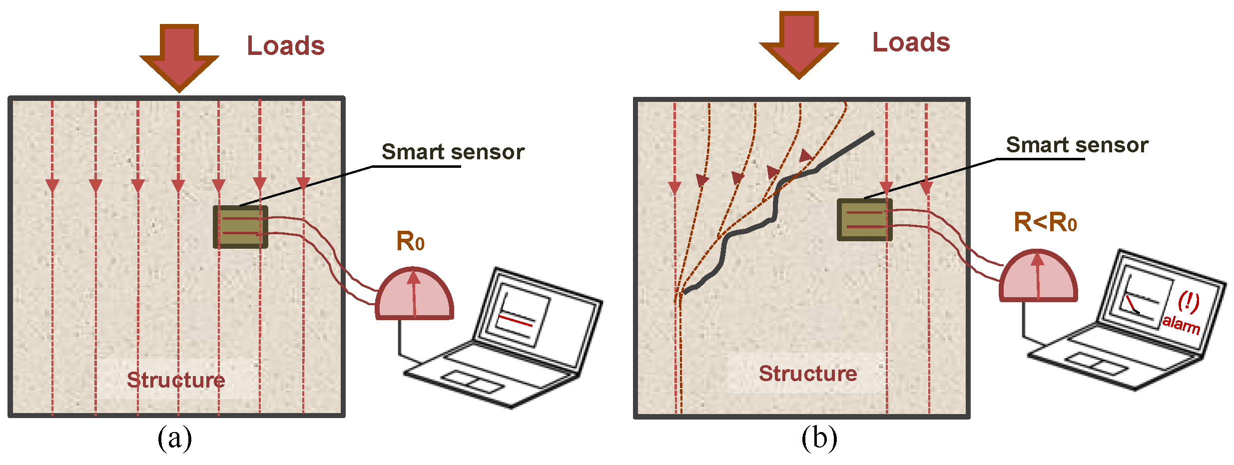
2. Smart Sensing Principles

Of interest to this research are smart composite materials able to self-sense their state of strain. This sensing ability is carried out through electrical measurements: the variations in their electrical characteristics, e.g., resistance or impedance, could be correlated with their deformation. The strength of these smart materials is in the possibility to use them as embedded strain sensors within the load-bearing elements of constructions, or as load-bearing elements fully made of sensing material (Figure 1a) [13,14]. Reliable sensing models are needed, which analytically relate strain to electrical properties, and a repetitive production procedure needs to be established. If the stress/strain field changes, due to a variation in loads, or the development of cracks, the electrical properties, e.g., electrical resistance (R), change (Figure 1b). The data acquisition system, if correctly calibrated, can evaluate critical variations of such electrical features, thus identifying a dangerous behavior of the element [15,16]. This technology is particularly useful for the quick and preliminary assessment of constructions required to be performed after exceptional natural or anthropic events, for the regular periodic controls during the service life, and before the scheduling of effective maintenance and interventions. In addition, unlike traditional sensors, composite sensors are made of the same matrix as the structures where they are implemented, leading to an increased quality of bonding between the sensor and structure. By detecting the variations in structural behavior, they could reveal losses in performance, damages, and cracks, which are all signs of a possible incipient failure. The modifications of the internal diffusion of loads may occur due to exceptional events, such as earthquakes, typhoons, and landslides, or simply due to the degradation of the structure [17]. Figure 1 is a conceptual representation of a possible scenario of variation in loads’ diffusion, due to the formation of a crack; in this case, the loads on the embedded smart sensor decrease, causing a subsequent decrease in its electrical resistance.

3. State of the Art of Smart Materials for SHM

Scientific interest in smart materials is growing rapidly, mainly due to their enhanced capabilities and their versatility in different fields of engineering [18,19]. In civil engineering, smart cement-based materials appear to be particularly suitable for various applications [20,21,22]. As a matter of fact, concrete is one of the most adopted constructive materials, and, due to its composite nature, it permits tailored modifications for specific purposes. The use of additives and fillers is quite common, especially for enhancing mechanical or rheological properties [23].
Recently, the development of chemistry and materials science improved the availability of particles and fibers with peculiar properties, above all for nanosized ones [24,25].

3.1. Disperion of Fillers in Cementitious Materials

Concrete could be considered a water-based admixture, so the dispersion of hydrophobic fillers, as most of the carbon-based ones are, could be critical. A good dispersion of the fibers is important to guarantee the homogeneity of the material and of its behavior [26,27]. Researchers have used various methods to obtain a satisfactory dispersion, which can be summarized as follows: (i) mechanical methods, through high-speed stirrers; (ii) sonication, by use of a tip or a bath; (iii) dispersant additives; (iv) chemical methods, with internal modification of the chemical structure of the matrix; and (v) functionalization, through a superficial modification [28,29]. The sonication method is the most effective for nanosized fillers, but it can only be adopted for small amounts of materials. Mechanical methods are not equally efficient, but can be applied on a larger scale; for this reason, such methods are more suitable in typical applications for civil engineering. Moreover, considering micro-sized fillers, they are often sufficiently effective. The mechanical methods are sometimes coupled with the use of additives, such as dispersants or surfactants, which help the separation of the bundles. These should be used carefully as they can affect the properties of the composite material. The two latter methods are not always useful, because, even if they allow us to obtain an optimal dispersion, they usually determine a strong modification of the components, thus deteriorating the enhanced properties of the composites [30,31]. Surely, the dispersing method should be tailored to the specific matrix and filler.

3.2. Fillers for Enhanced Electrical Properties of Cementitious Materials

The number of different types of fillers available in the literature and the market is increasing more and more. In particular, the progress of nanotechnology has produced several advanced nanoparticles and nanofillers which possess different and enhanced properties compared to their micro- or macro-scaled alternatives [32]. Among the available ones, carbon-based fillers demonstrate good applicability in civil engineering, enhancing the mechanical and electrical properties of the materials they are dispersed in. In cementitious materials, carbon fillers provide conductive and piezoresistive capabilities which are suitable characteristics for monitoring applications [33,34], oriented towards the self-integrity over time or towards the determination of the mechanical self-state actuated by external loads. The mechanical state of the composite material affects the overall electrical characteristics, in terms of conductivity, primarily set by the amount and morphology of dispersed fillers and their interactions with the composite matrix. Based on these principles, advanced monitoring is carried out by measuring the variation in resistance over time, which is correlated with the external loads or material degradation. If the strain/stress field changes, resistance—or conductivity—changes, identifying possible risky conditions, as described in Section 1. The effect of the fillers in the cementitious matrix also strongly depends on their aspect ratio and chemical structure. Carbon-based inclusions that could be effective for monitoring purposes are nanometric (e.g., nanotubes [35,36], carbon black [37,38], graphene [39,40], nanofibers [41,42]) or micrometric (e.g., microfibers [14,43], graphite [44,45]). Studies in the literature also demonstrate the enhanced effect of a hybrid composition of fillers, mixing materials with different characteristics [46,47].

3.3. Advantages of Smart Sensors

As already mentioned, the advantages of smart sensors are that they are made of the same matrix as the structure to be monitored, with a similar durability, maintenance, and mechanical properties, and they can be easily embedded within structural elements, or constitute part of the structure. Traditional sensors are usually applied on the surface and are quite delicate. Moreover, they can be placed only on a limited number of points, and need special maintenance. Additionally, the cost of a traditional sensor network is higher. On the contrary, smart self-sensing sensors could be diffused in the structures, generating a de facto spread and permanent monitoring system of the structural behavior [48,49]. Such sensors can be effectively applied also to infrastructures, as a part of roads or bridges, for traffic monitoring and management, weigh-in-motion, vibration-based SHM and damage detection [50,51,52,53]. Strategic features in smart cities are other possible applications. The smart monitoring system could simply indicate the occurrence of performance modifications, which exceed the limits of normal conditions, as a sign of the presence of cracks or great changes in strain field dangerous for the integrity of the structure and its users.

3.4. Aim of the Presented Research

For this study, the authors developed a research work aiming at investigating the potentialities of different types of carbon-based fillers as additives for self-sensing cementitious materials, demonstrating their effectiveness in static and dynamic SHM, if well designed, produced and calibrated [54,55,56]. With respect to previous literature works, the present paper aims to compare the behavior of sonicated and mechanically mixed cementitious matrices doped with different types of carbon inclusions, thus investigating the different possible applications of the various mixes focusing on reliability and reproducibility of smart sensors. A promising mechanically mixed carbon-doped composite is then adopted to prepare a plate with a novel configuration of point-type electrodes and examine its possible applications. Compared to the line-type electrodes studied in previous literature works, the proposed distributed point-type electrodes are found to be more effective and easier to install, supporting a wide range of monitoring strategies such as electrical tomography for crack detection.

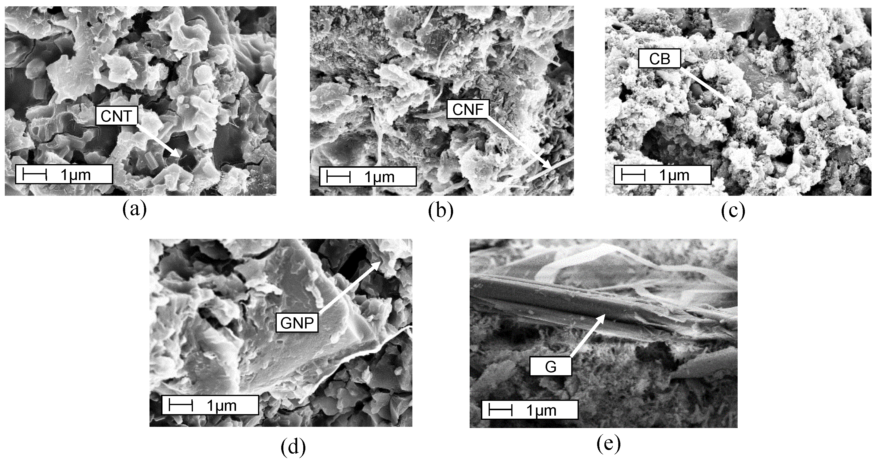
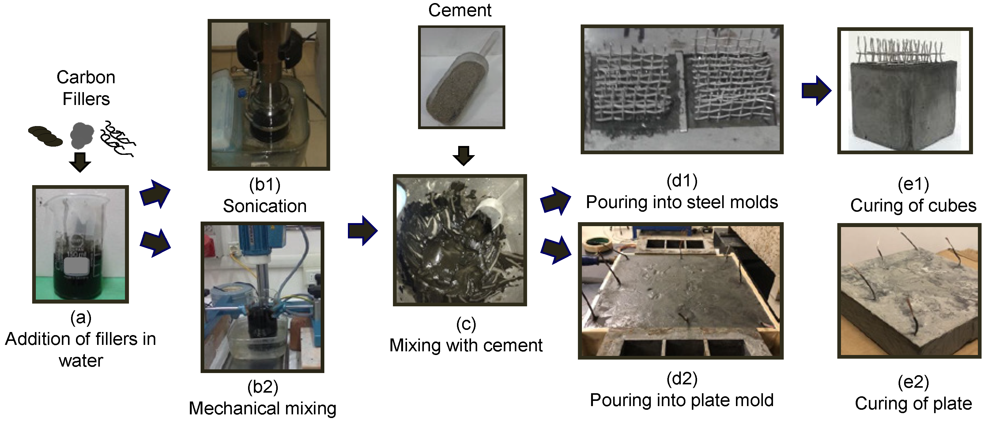
4. Materials and Sample Preparation

Strain-sensing materials are composed of two main components: a constructive matrix and electrically conductive fillers. The matrix is the core material that possesses suitable mechanical strength, while the conductive fillers are responsible for the improvement in electric conduction and piezoresistive properties. The electrical properties are enhanced by adding the optimal amount of fillers, which depends on the characteristics of the matrix, and of the fillers themselves. The presence of electrodes can affect the electrical measurements; for this research, the authors made the choice of embedding them in the sensors in order to limit the contact resistance.
For this study, the electromechanical performances of the various composites are first investigated on cubic samples with a 51 mm side length, which include four embedded steel-net electrodes placed at mutual distances of 10, 20, and 10 mm. The samples’ dimensions and appearance are illustrated in Figure 2. Figure 2a reports the setup of the electromechanical tests on cubes, with the load and electrical acquisition systems, the sketch of the connection of the electrodes involved in the measurements, and the direction of the applied load.
Figure 3 shows the dimensional characteristics of the graphite–cement composite middle-scale slab sample subjected to compressive loads, the placement of the electrodes, and the sketch of the setup of the tests. The manufactured slab sensor has side lengths of 30 cm and a thickness of 4 cm. The graphite–cement weight concentration is 5%, a value that allows the composite to exhibit sufficient workability for a water-to-cement ratio of 0.45. The slab sample is equipped with 8 point-type electrodes placed along the perimeter, made of stainless-steel bolts of M10 N-type. The copper wires connecting the electrodes to the data acquisition system are wrapped around the thread and fixed between the nut and bolt head. The embedded parts of the wires are electrically insulated.
The selected electrically conductive fillers for the specimens, made of cement paste, are all carbon based, with varying dimensions and aspect ratios. Both features impact the conductivity of the composite material. The adopted particles are carbon nanotubes (CNT), carbon nanofibers (CNF), carbon black (CB), graphene nanoplatelets (GNP), and graphite (G). Figure 4 shows the micrographs of fragments of each doped material obtained from a Scanning Electron Microscope (SEM) at the same magnification in the Microscopy Laboratory of the Group of Materials Science and Technology of University of Perugia.
In the SEM pictures, the structures of the cementitious matrix and the different dispersed inclusions are visible. Figure 4a,b show the composite cement paste with CNTs and CNFs, respectively; their dispersion is good, and their 1-dimensional shape is recognizable. CB appears 0-dimensional in Figure 4c, while the 2-dimensional characteristics of GNP and G are observable in Figure 4d,e. The different dimension characteristics of the fillers are clearly visible in the SEM micrographs; the corresponding numerical values are reported in Table 1, together with other physical properties of the carbon-based fillers.
Carbon nanotubes are Multi-Walled Graphistrength C-100 fillers, provided by Arkema (Paris, France); they have an average diameter of 10–15 nm, length of 0.1–10 μm, and a specific surface area of about 100–250 m2/g. Carbon nanofibers are type Pyrograf-III carbon nanofibers PE-19-XT-LHT (Cedarville, OH, USA), having diameters between 70 and 200 nm and lengths between 50 and 200 μm. Carbon Black is Printex XE-2B Orion (Frankfurt am Main, Germany), and formed by spherical pure elemental carbon particles having an average diameter of 30 nm. Graphene nanoplatelets, in the forms of packed graphene with a diameter of 15 μm and a thickness of approximately 3–10 nm, are produced by Cheap Tubes Inc. (Cambridgeport, VT, USA) Graphite is a fine powder, with a particle size of about 50 μm, provided by Frigerio s.r.l. (Perugia, Italy) Graphite and graphene nanoplatelets appear as gray powder, while carbon nanotubes, carbon-nanofibers, and carbon black have the appearance of black powders. The core material of the matrix where the fillers are dispersed is Portland cement type 42.5R. The addition amounts of fillers are 1.5% or 2.0%, calculated by the weight of cement. The water-to-cement ratio of all the mixes is 0.45. The manufacturing of carbon-doped cementitious specimens was carried out through two main phases: (i) preparation of water suspension with carbon-based fillers, and (ii) preparation of the the cementitious dough. The first phase of the preparation began by adding the desired amounts of carbon inclusions in the water (Figure 5a), mixing until homogeneous. Two possible mixing procedures were evaluated: sonication (Figure 5(b1)) and mechanical mixing (Figure 5(b2)).
Sonication is the procedure where sound waves with ultra-frequencies decay the particle clusters and increase the dispersion quality. Such a methodology utilizes Sonicator Bioblock Vibra Model 75043 with a power of 225 W. The sonication was carried out for 30 min, with a 30 s break after the first 15 min. Mechanical mixing was carried out through a Dispermat stirrer which operated for 60 min with 4000 rounds per minute. Afterwards, the cement was added to the mixed water suspension (Figure 5c).
The mixing process of composite dough continued mechanically, until the composite dough became homogeneous. For the preparation of cubic samples, the compound was then cast into pre-oiled steel molds (Figure 5(d1)), and stainless-steel nets with dimensions of 2 cm width and 4 cm height were embedded as electrodes. The cubic specimens were unmolded after 48 h and left for curing in laboratory conditions for 28 days (Figure 5(e1)). The slab sample was produced through the use of a plastic mold. During the pouring, 8 point-type electrodes were placed along the perimeter of the slab (Figure 5(d2)). The plate was unmolded after 48 h and cured in laboratory conditions for 28 days (Figure 5(e2)). The preparation process of the different typologies of samples is visualized in Figure 5. After the curing period, the cubic specimens were assessed for their strain sensing capabilities under cyclic compression loads, while the plate was subjected to compressive step loads which simulated the traffic loads.
Electromechanical tests of this study were carried out through the simultaneous applications of voltage and compression force, recording sample resistance and induced strain. The typical setting of the electromechanical test and equivalent circuit model is illustrated in Figure 6a, the setup is displayed in Figure 6b, and the compression load pattern is shown in Figure 6c, while the setup of the tests on plate is presented in Figure 7, together with the sensing scheme, the equivalent electrical circuit model (Figure 7a) and the instrumentations (Figure 7b).

5. Modeling and Evaluation of Self-Sensing Capabilities

The aim of electromechanical testing cubic samples is to investigate the sensitivity of different types of carbon-doped materials, analyzing the model that correlates to the mechanical and electrical states. This was carried out through the evaluation of the conductivity of the material, the gauge factor, λ , and the reliability of the linear fit model of readings established through λ . The conductivity of the composite material was obtained by measuring the resistance of the specimen in the unloaded state. It is a strong indicator for the best doping level that exhibits an adequate piezoresistivity. During the electromechanical tests, the initial parts of the recorded resistance time histories were used for its calculation. The mean resistance values obtained through these initial parts were taken as the unloaded state resistance values ( R 0 ). The cube model of specimens illustrated in Figure 6a shows that the general resistance formulation for rectangular solids can be employed to calculate the conductivity of the sample material ( 1 / ρ ). Hence, the conductivity is formulated as:
1 / ρ = e R 0 l 2
Considering the given sample dimensions, the above formulation yields:
1 / ρ = 1 0.125 R 0 S · m 1
followed by the gauge factor formulations for the cube samples and the plate sample, given by Equations (3) and (4), respectively [22]:
λ = dR R ε = d ρ ρ ε + ( 1 + 2 ν )
λ = dR R ε = d ρ ρ ε + ( 1 )
where R is the resistance measured through the electrodes of the sample, ρ is the resistivity of the composite material, and ε is the induced strain in a direction perpendicular to the electrode separation, with a negative sign under compression. The last terms of the derived equations concern the geometric effects of body deformations on the resistance of the volume between the electrodes, where Poisson’s ratio is denoted by ν . The governing equation of self-sensing indicates that the piezoresistivity term d ρ / ρ / ε can directly affect the magnitude of the gauge factor. In fact, for piezoresistive smart composites, this term dominates over ( 1 + 2 ν ) .
The discretized version of Equation (3) and discretized-adapted version of Equation (4) were used for assessments of the gauge factors of linear sensing models of specimens obtained through the electromechanical tests. The discrete formulations are given as Equations (5) and (6), for the cube samples and slab sample, respectively:
λ = Δ R ( t ) R 0 ε ( t )
λ * = Δ R ( t ) R 0 F ( t )
where, λ * denotes the pseudo gauge factor, calculated with respect to the force time history, more suitable for the middle-scale test carried out in the research.

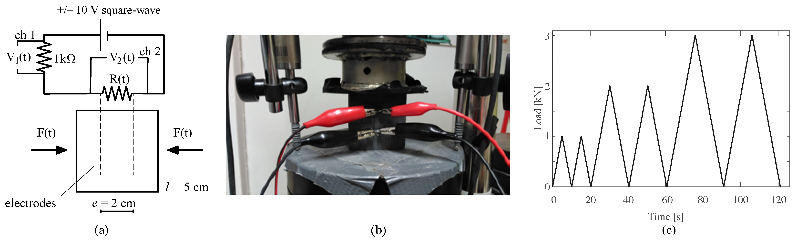
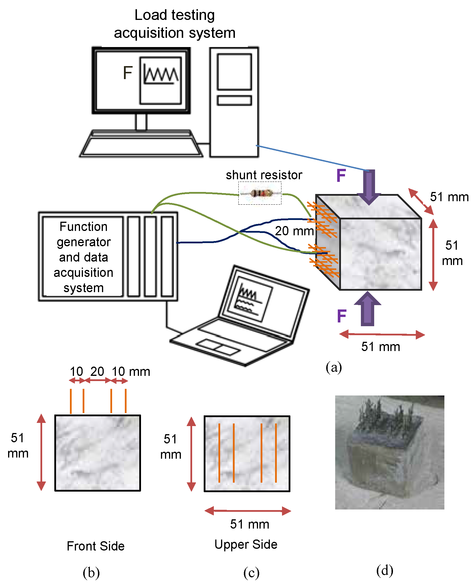
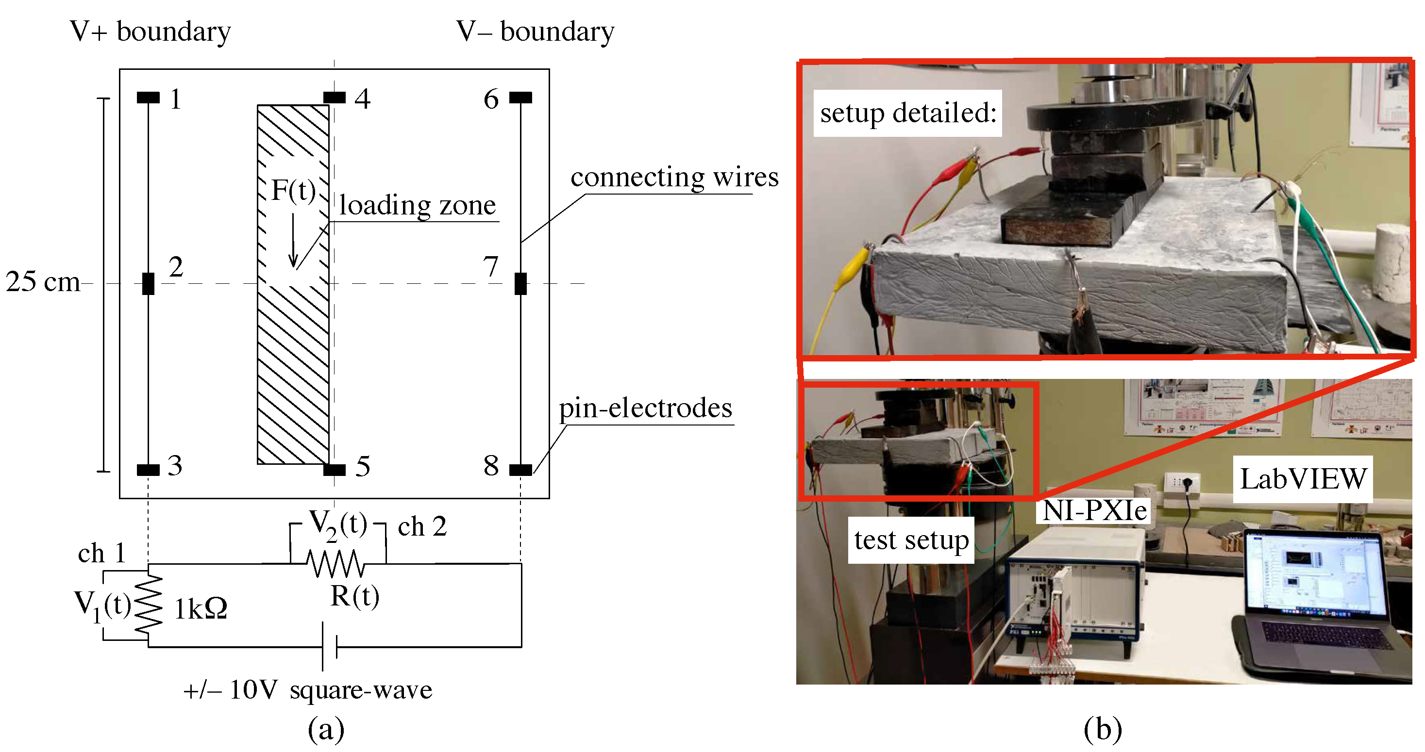
6. Electrical Setup and Instrumentation for Electromechanical Tests

Equations (5) and (6) could be calculated after the synchronous acquisitions of resistance, R ( t ) , strain, ε ( t ) and force F ( t ) . During the tests, ε ( t ) was recorded, with the values from three high-precision LVDT transducers being averaged, each having 1 cm of maximum displacement, located at 120-degree angles in the plane. On the opposite lateral sides of the cubes selected as benchmarks for calibrating LVDT readings, 2 cm long strain gauges were attached. The cyclic load pattern was applied to the tested samples by using the computer-controlled compression machine model Advantest 50-C7600 by Controls with a maximum load capacity of 15 kN. The cube samples were subjected to the compression load cycles described in Figure 6c and were uniformly distributed on the cross section of 2500 mm2. Accordingly, the load increments are 1–2–3 kN, which correspond to compression stresses of 0.4–0.8–1.2 MPa, respectively. The compression load was applied to slab sample through an electrically insulated rectangular steel frame with a base of 25 cm × 6 cm. The tests comprise two different cycles of step-load with increasing maximum loads, and with periods of 10 s. The first cycle of loads had increments of 2–4–6–8–4.5 kN, corresponding to compression stresses of 0.13–0.26–0.4–0.53–0.3 MPa, respectively; the second cycle had increments of 2–4–6–3.5 kN, corresponding to stress cycles of 0.13–0.26–0.4–0.23 MPa. These values are comparable to the stresses induced by vehicle axles on the road pavements.
The electric circuit is composed of a voltage supplier, the tested specimen, a shunt resistor of 1 kΩ, and two channels of the voltage reader. The two channels record the voltage-time histories through the shunt resistor (V1) and the sample (V2). For the cube samples, the test sample was connected to the electric circuit by the inner electrodes, which are 2 cm apart, as shown in Figure 6a. For the slab sample, the electrodes 1–2–3 and 6–7–8 were connected to form electrically high (V+) and low (V−) boundaries, respectively (Figure 7a). Both test setups adopted the two-point sensing scheme. Accordingly, for the electrical measurements of the experimental setup, a DAQ model NI PXIe-1092 was employed. The square wave voltage input of +/− 10 V at 1 Hz was sourced by a NI PXIe-4138 unit that generates voltage signals as time-dependent functions. The use of square waves reduces the polarization drift that is caused by the dielectric matrix of the carbon-doped composites [57]. Voltages were read through two different channels ch1 and ch2 in Figure 6a of a 32-channel Analog Input Module NI PXIe-4302 that is controlled by a NI PXIe-8840 unit. The sample rate of the analog input was selected as 10 Hz, being compatible with a 1 Hz square wave voltage input. The computation of resistance time history was carried out by selecting the 80% charge point on each positive part of the acquired square wave. The programming of the DAQ was conducted in the LABVIEW environment [58]. The resistance time histories R ( t ) of Equations (5) and (6) were then obtained as:
R ( t ) = V 2 ( t ) I ( t )
and, I ( t ) was obtained through the use of shunt resistor:
I ( t ) = V 1 ( t ) 1000
The linear sensing models of specimens were established through the correlations of the processed resistance, strain (cube samples) and force (slab sample) time histories, using the linear analytical models defined by Equations (5) and (6).

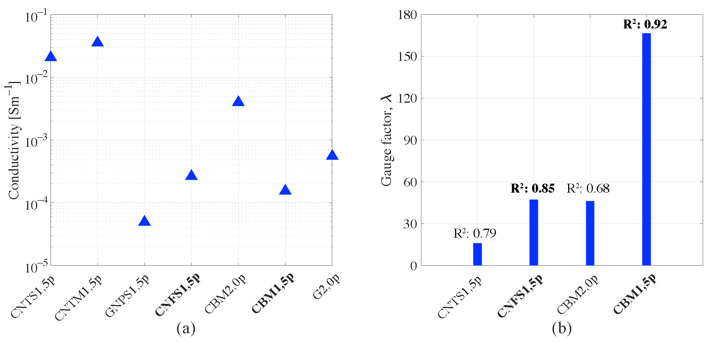
7. Results of Electromechanical Tests

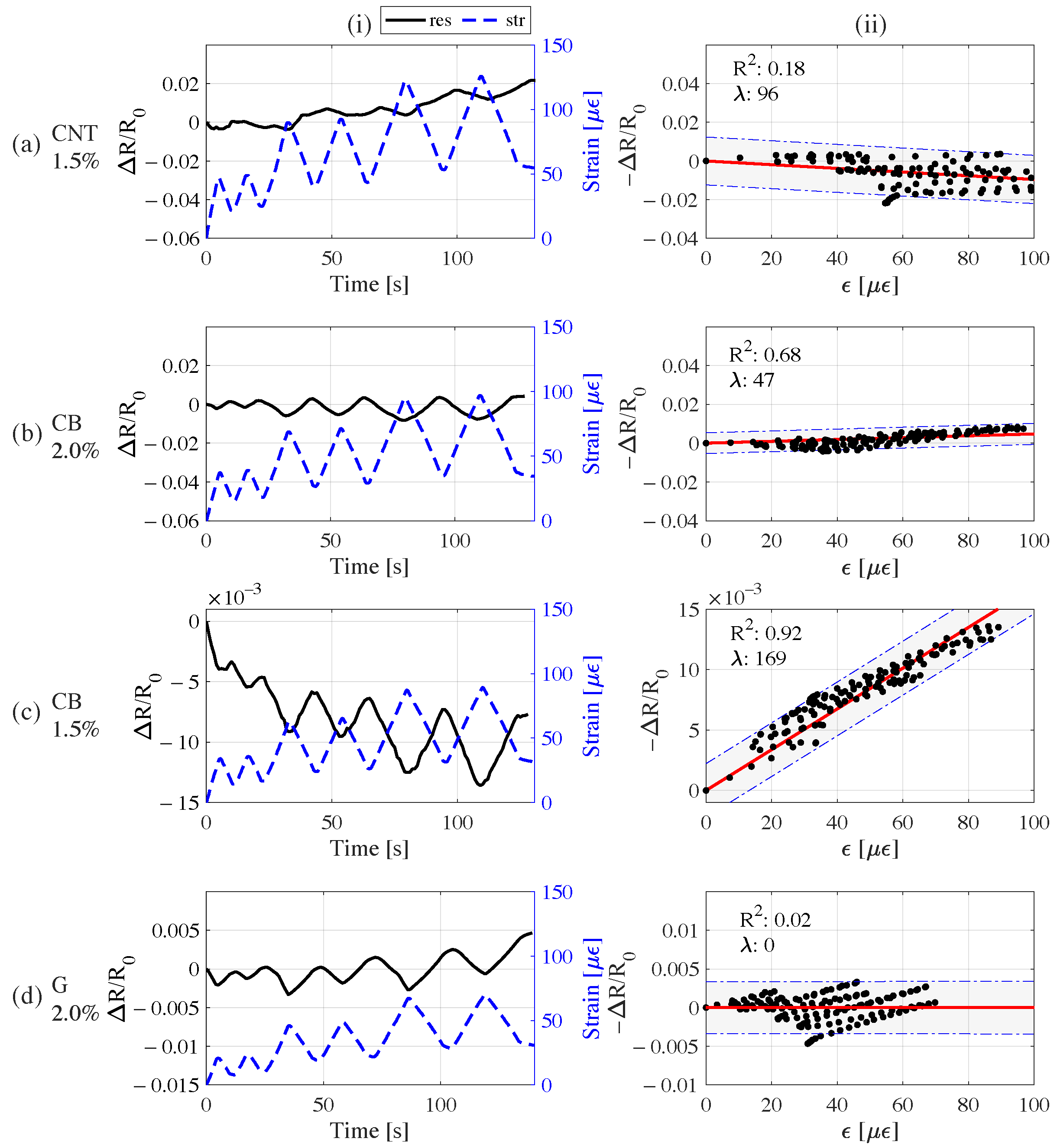
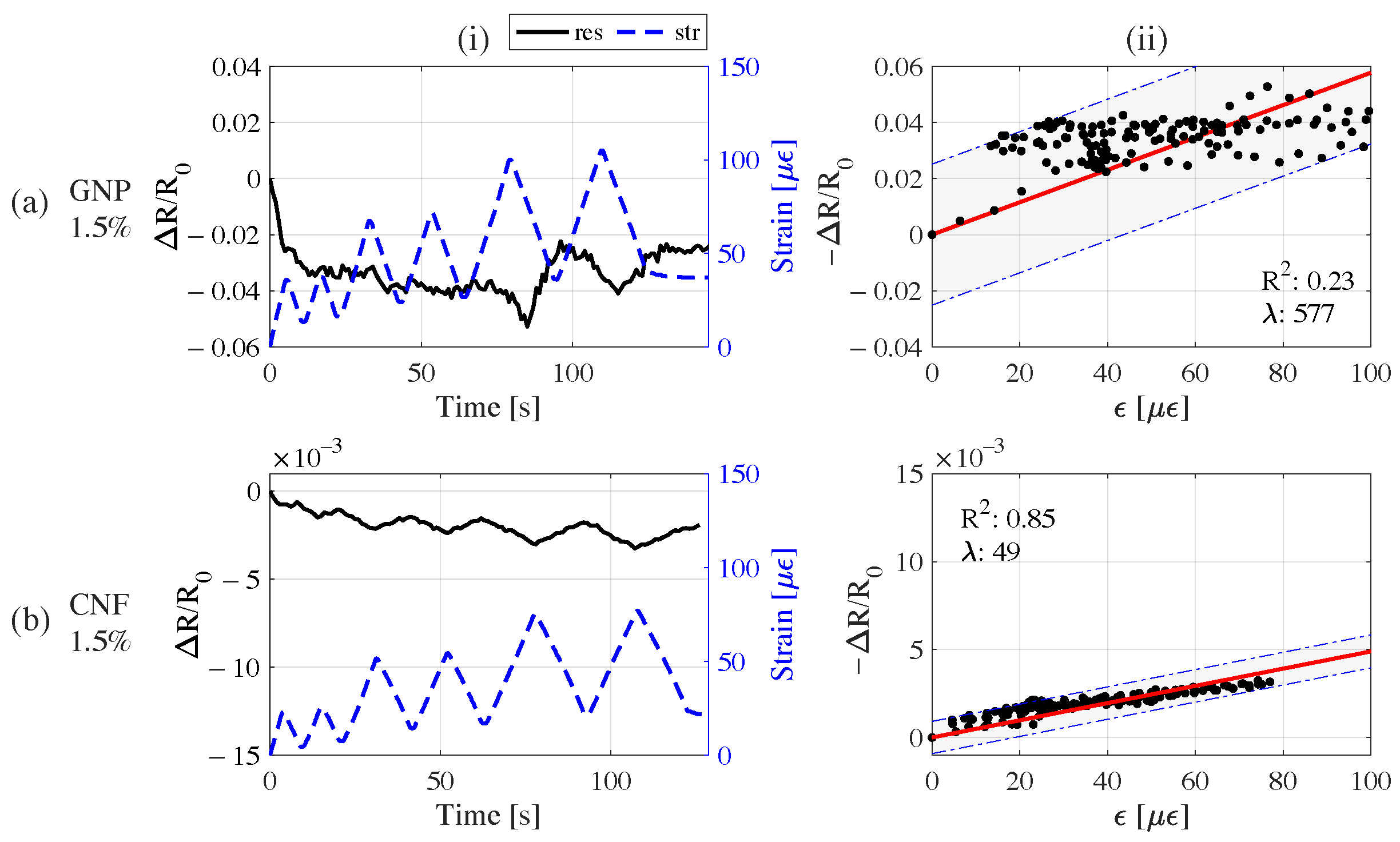
7.1. Results of Cubic Samples

The investigated samples of the study are (i) sonicated ones with 1.5% of CNT fillers (from [56]), CNF and GNP with the code names CNTS1,5p, CNFS1,5p and GNPS1,5p, respectively; and (ii) mechanically mixed ones with 1.5% of CNT and CB, and 2% of CB and G with the code names CNTM1,5p, CBM1,5p, CBM2,0p and GM2,0p.
The signal responses of the sonicated samples with CNF and GNP, as well as their linear fit models of sensing, are shown Figure 8. There, the CNF sample exhibits a good signal response for the given load pattern, while the signal response of GNP was found to be unreliable despite the large gauge factor due to large variations in sample resistance uncorrelated to induced strain time history. The linear fit model of the CNFs sample was found to be reliable. The gauge factor was calculated as 49 with a R2 of 0.85.
Similarly, the outcomes of tests conducted on mechanically mixed samples are summarized in Figure 9. Accordingly, the composite sample with 1.5% CB was found to exhibit the best performance. Other samples exhibited a positive shift towards the increase in sample resistance despite the growing residual strain during the load cycles. The influence of polarization drift was significant when the R2 values of linear models were low. In particular, the performance of the mix with CNTs was not satisfactory. The graphite sample shows a significant polarization despite the synchronized local variations with the strain peaks: such a polarization is probably caused by the doping level well below the percolation zone. CB with a 2.0% doping level also exhibited a polarization drift that reduced the sensing quality. On the other hand, the 1.5% CB sample produced a clean signal response to the strain, supporting the hypothesis that it is close to the optimum doping level. According to the linear fit models, as expected, the sample with 1.5% CB had high reliability with 92% of R2, and its linear model has a gauge factor of 169. With these results, the composite material with 1.5% CB was rated as the best-performing sample among the sample set. It is worth mentioning that 2.0% CB exhibited a sufficient response to the induced load pattern, but it was affected by the polarization drift and its gauge factor is lower. Likewise, the results of the 2.0% G sample were found to be unreliable since the response was influenced heavily by the polarization drift. The findings of electromechanical tests on the samples are summarized below in Figure 10.
Overall, the conductivity and performance of linear models were found to be consistent (Figure 10). For CB samples, the increase in the doping level from 1.5% to 2.0% determined a huge increase in conductivity, resulting in a considerably lower performance; this is probably due to overpercolation. In general, sonication appears to be the most effective method for mixing nanosized fillers during material preparation, even if it is not suitable for large-scale applications as required by buildings and infrastructures. On the other hand, the mechanical method is promising for particle-type fillers such as carbon black and graphite. In particular, graphite is especially suitable for large-scale production for its high conductivity. Moreover, graphite is not harmful to the environment, as nanosized particles can be.

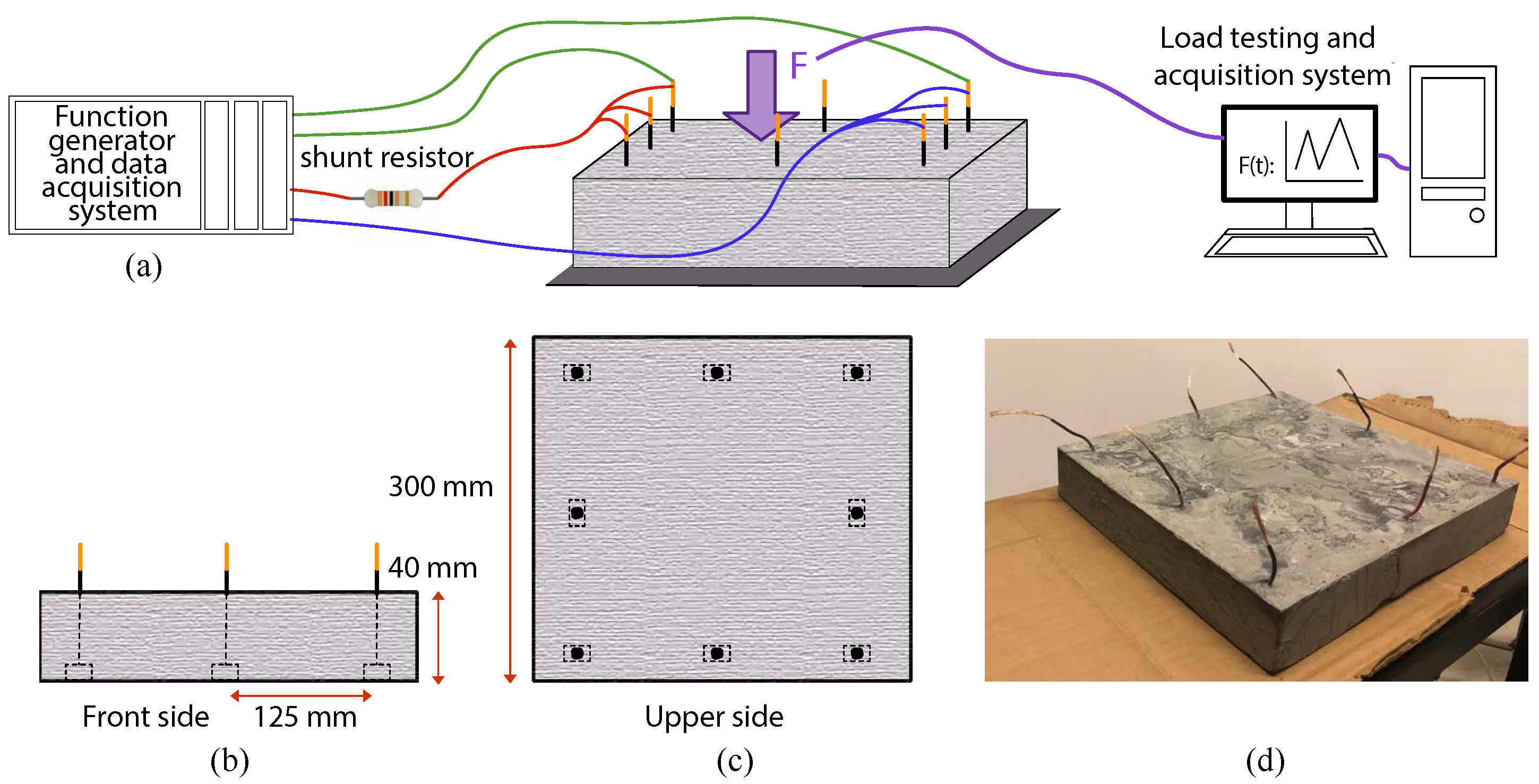
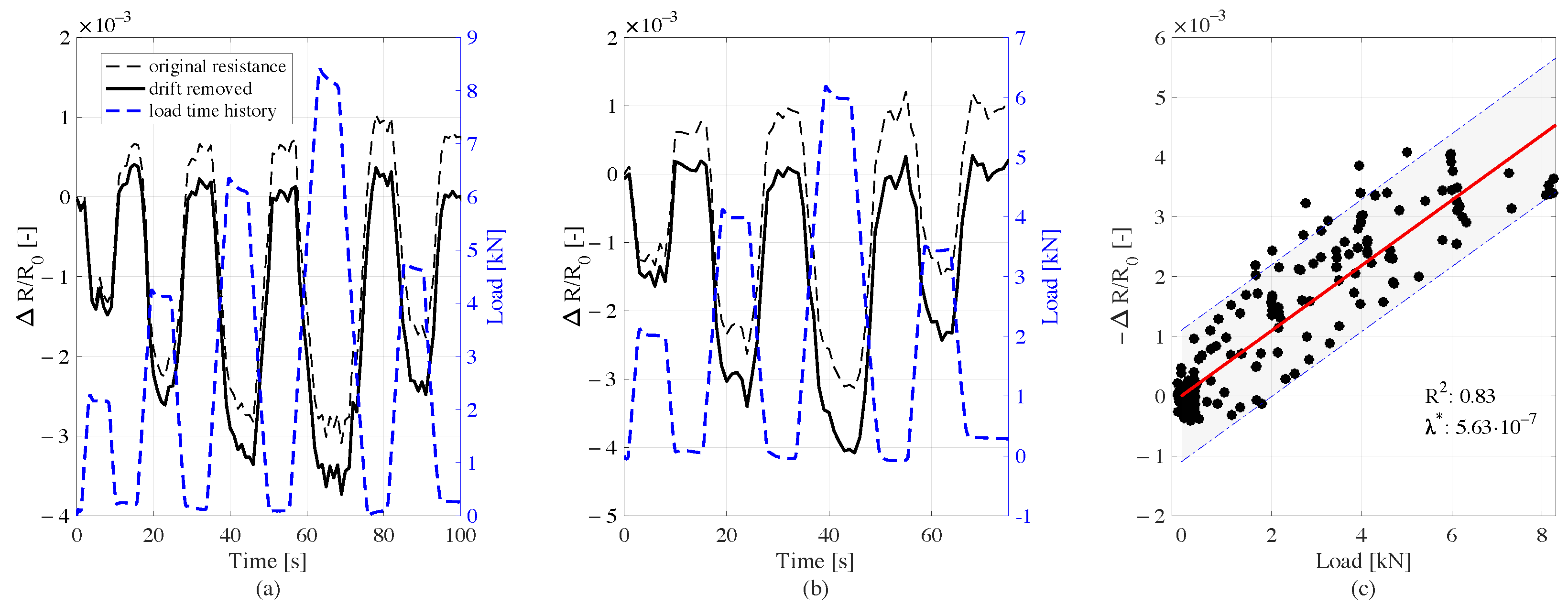
7.2. Results of Medium-Scale Graphite—Cement Composite Sample

The electrical response generated by the plate is shown in Figure 11. The obtained resistance time history signals exhibit an upwards drift towards the increase in the sample resistance, removed through post processing. The results demonstrate that the electrical output well reproduces the load histories (Figure 11a,b). Moreover the sample shows a sensitive behaviour, with a high linearity of the signals (Figure 11c). The electromechanical tests on the medium-scale sample proved that the self-sensing cementitious materials doped with carbon-based fillers, if well arranged, are able to also identify loads at the meso-scale, and represent the first step toward field applications at real scales.

8. Conclusions

This study investigated the different production methodologies that can be adopted for producing self-sensing cementitious composites doped with conductive carbon fillers. The different production steps and load-sensing methodologies for small- and medium-scale samples were introduced and discussed. For testing the sensing capabilities of the various materials, electromechanical tests were conducted on small cubic samples by applying cyclical compressive loads. Then, step loads, which simulated traffic loads, were used to determine the load histories for electromechancial testing on a medium-scale plate with a novel configuration of electrodes, specifically to facilitate field deployment. The results demonstrate that, if properly designed, self-sensing carbon-doped cementitious composites can be quite effective for strain monitoring in buildings and road infrastructures in the real world. The cost of the applications of such carbon-modified cementitious materials depends on the cost and amount of inclusions compared to the unit cost of the base material. Nanoparticles are more expensive than microfillers and generally viable for local applications in critical regions of a structure. On the contrary, cheaper and larger fillers such as graphite, would determine, at the percentages investigated in the paper, an increase in the cost per cubic meter of concrete of about 20%. This relatively low impact, compared to the achieved benefits, may allow large-scale and distributed applications in civil constructions.

Author Contributions

The following contributions were made by the authors: conceptualization, A.D. and F.U.; methodology, A.D. and H.B.B.; software, H.B.B.; validation, A.D. and F.U.; resources, F.U.; writing—original draft preparation, A.D. and H.B.B.; writing—review and editing, A.D., G.C. and F.U.; visualization, A.D. and H.B.B.; supervision, A.D. and F.U. All authors have read and agreed to the published version of the manuscript.

Funding

This research received funding from the European Union’s Horizon 2020 research and innovation programme under Grant Agreement N. 765057-SAFERUP! Project. Financial support from the Italian Ministry of University and Research (MUR) in the framework of the Project FISR 2019: “Eco Earth” (code 00245) is also gratefully acknowledged.

Institutional Review Board Statement

Not applicable.

Informed Consent Statement

Not applicable.

Data Availability Statement

The data that support the findings of this study are available from the authors upon reasonable request.

Acknowledgments

The authors would like to gratefully acknowledge the Group of Materials Science and Technology of University of Perugia, in particular Luigi Torre and Marco Rallini, for the support provided in chemical investigations.

Conflicts of Interest

The authors declare no conflict of interest.

References

  1. Na, W.S.; Baek, J. A review of the piezoelectric electromechanical impedance based structural health monitoring technique for engineering structures. Sensors 2018, 18, 1307. [Google Scholar] [CrossRef] [Green Version]
  2. Aabid, A.; Parveez, B.; Raheman, M.A.; Ibrahim, Y.E.; Anjum, A.; Hrairi, M.; Parveen, N.; Mohammed Zayan, J. A review of piezoelectric material-based structural control and health monitoring techniques for engineering structures: Challenges and opportunities. Actuators 2021, 10, 101. [Google Scholar] [CrossRef]
  3. Rallini, M.; Natali, M.; Monti, M.; Kenny, J.M.; Torre, L. Effect of alumina nanoparticles on the thermal properties of carbon fibre-reinforced composites. Fire Mater. 2014, 38, 339–355. [Google Scholar] [CrossRef]
  4. Musso, S.; Tulliani, J.M.; Ferro, G.; Tagliaferro, A. Influence of carbon nanotubes structure on the mechanical behavior of cement composites. Compos. Sci. Technol. 2009, 69, 1985–1990. [Google Scholar] [CrossRef]
  5. Zaccone, M.; Frache, A.; Torre, L.; Armentano, I.; Monti, M. Effect of filler morphology on the electrical and thermal conductivity of pp/carbon-based nanocomposites. J. Compos. Sci. 2021, 5, 196. [Google Scholar] [CrossRef]
  6. Monteiro, A.; Loredo, A.; Costa, P.; Oeser, M.; Cachim, P. A pressure-sensitive carbon black cement composite for traffic monitoring. Constr. Build. Mater. 2017, 154, 1079–1086. [Google Scholar] [CrossRef]
  7. Konsta-Gdoutos, M.S.; Metaxa, Z.S.; Shah, S.P. Highly dispersed carbon nanotube reinforced cement based materials. Cem. Concr. Res. 2010, 40, 1052–1059. [Google Scholar] [CrossRef]
  8. Azhari, F.; Banthia, N. Carbon Fiber-Reinforced Cementitious Composites for Tensile Strain Sensing. ACI Mater. J. 2017, 114, 129–136. [Google Scholar]
  9. Rainieri, C.; Pannunzio, C.; Song, Y.; Fabbrocino, G.; Schulz, M.J.; Shanov, V. The status of research on self-sensing properties of CNT-cement based composites and prospective applications to SHM. Key Eng. Mater. 2013, 569, 759–766. [Google Scholar] [CrossRef]
  10. Han, J.; Pan, J.; Cai, J.; Li, X. A review on carbon-based self-sensing cementitious composites. Constr. Build. Mater. 2020, 265, 120764. [Google Scholar] [CrossRef]
  11. Chung, D. A critical review of piezoresistivity and its application in electrical-resistance-based strain sensing. J. Mater. Sci. 2020, 55, 15367–15396. [Google Scholar] [CrossRef]
  12. Chen, M.; Gao, P.; Geng, F.; Zhang, L.; Liu, H. Mechanical and smart properties of carbon fiber and graphite conductive concrete for internal damage monitoring of structure. Constr. Build. Mater. 2017, 142, 320–327. [Google Scholar] [CrossRef]
  13. Sarwary, M.; Yıldırım, G.; Al-Dahawi, A.; Anıl, Ö.; Khiavi, K.A.; Toklu, K.; Şahmaran, M. Self-sensing of flexural damage in large-scale steel-reinforced mortar beams. ACI Mater. J. 2019, 116, 209–221. [Google Scholar] [CrossRef]
  14. Hou, T.C.; Lynch, J.P. Conductivity-based strain monitoring and damage characterization of fiber reinforced cementitious structural components. In Smart Structures and Materials 2005: Sensors and Smart Structures Technologies for Civil, Mechanical, and Aerospace Systems; International Society for Optics and Photonics: Bellingham, WA, USA, 2005; Volume 5765, pp. 419–429. [Google Scholar]
  15. Baeza, F.J.; Galao, O.; Zornoza, E.; Garcés, P. Multifunctional cement composites strain and damage sensors applied on reinforced concrete (RC) structural elements. Materials 2013, 6, 841–855. [Google Scholar] [CrossRef] [Green Version]
  16. Gupta, V.; Sharma, M.; Thakur, N. Mathematical modeling of actively controlled piezo smart structures: A review. Smart Struct. Syst. 2011, 8, 275–302. [Google Scholar] [CrossRef]
  17. Shivashankar, P.; Gopalakrishnan, S. Review on the use of piezoelectric materials for active vibration, noise, and flow control. Smart Mater. Struct. 2020, 29, 053001. [Google Scholar] [CrossRef]
  18. Ali, A.; Andriyana, A. Properties of multifunctional composite materials based on nanomaterials: A review. RSC Adv. 2020, 10, 16390–16403. [Google Scholar] [CrossRef]
  19. Chen, S.; Collins, F.G.; MacLeod, A.J.N.; Pan, Z.; Duan, W.; Wang, C.M. Carbon nanotube–cement composites: A retrospect. IES J. Part A Civ. Struct. Eng. 2011, 4, 254–265. [Google Scholar] [CrossRef]
  20. Konsta-Gdoutos, M.S.; Danoglidis, P.A.; Falara, M.G.; Nitodas, S.F. Fresh and mechanical properties, and strain sensing of nanomodified cement mortars: The effects of MWCNT aspect ratio, density and functionalization. Cem. Concr. Compos. 2017, 82, 137–151. [Google Scholar] [CrossRef]
  21. Han, B.; Ding, S.; Yu, X. Intrinsic self-sensing concrete and structures: A review. Measurement 2015, 59, 110–128. [Google Scholar] [CrossRef]
  22. Birgin, H.B.; D’Alessandro, A.; Laflamme, S.; Ubertini, F. Smart graphite–cement composite for roadway-integrated weigh-in-motion sensing. Sensors 2020, 20, 4518. [Google Scholar] [CrossRef] [PubMed]
  23. Rashad, A.M. Effect of carbon nanotubes (CNTs) on the properties of traditional cementitious materials. Constr. Build. Mater. 2017, 153, 81–101. [Google Scholar] [CrossRef]
  24. Rainieri, C.; Song, Y.; Fabbrocino, G.; Schulz, M.J.; Shanov, V. CNT-cement based composites: Fabrication, self-sensing properties, and prospective applications to structural health monitoring. In Fourth International Conference on Smart Materials and Nanotechnology in Engineering; International Society for Optics and Photonics: Bellingham, WA, USA, 2013; Volume 8793, p. 87930V. [Google Scholar]
  25. Li, H.; Xiao, H.g.; Ou, J.p. A study on mechanical and pressure-sensitive properties of cement mortar with nanophase materials. Cem. Concr. Res. 2004, 34, 435–438. [Google Scholar] [CrossRef]
  26. D’Alessandro, A.; Tiecco, M.; Meoni, A.; Ubertini, F. Improved strain sensing properties of cement-based sensors through enhanced carbon nanotube dispersion. Cem. Concr. Compos. 2021, 115, 103842. [Google Scholar] [CrossRef]
  27. D’Alessandro, A.; Rallini, M.; Ubertini, F.; Materazzi, A.L.; Kenny, J.M. Investigations on scalable fabrication procedures for self-sensing carbon nanotube cement-matrix composites for SHM applications. Cem. Concr. Compos. 2016, 65, 200–213. [Google Scholar] [CrossRef]
  28. Hilding, J.; Grulke, E.A.; George Zhang, Z.; Lockwood, F. Dispersion of carbon nanotubes in liquids. J. Dispers. Sci. Technol. 2003, 24, 1–41. [Google Scholar] [CrossRef]
  29. Han, B.; Yu, X.; Ou, J. Multifunctional and smart carbon nanotube reinforced cement-based materials. In Nanotechnology in Civil Infrastructure; Springer: Berlin/Heidelberg, Germany, 2011; pp. 1–47. [Google Scholar]
  30. Rao, R.; Sindu, B.; Sasmal, S. Synthesis, design and piezo-resistive characteristics of cementitious smart nanocomposites with different types of functionalized MWCNTs under long cyclic loading. Cem. Concr. Compos. 2020, 108, 103517. [Google Scholar] [CrossRef]
  31. Shukrullah, S.; Naz, M.Y.; Mohamed, N.M.; Ibrahim, K.A.; AbdEl-Salam, N.M.; Ghaffar, A. CVD synthesis, functionalization and CO2 adsorption attributes of multiwalled carbon nanotubes. Processes 2019, 7, 634. [Google Scholar] [CrossRef] [Green Version]
  32. Yoo, D.Y.; You, I.; Youn, H.; Lee, S.J. Electrical and piezoresistive properties of cement composites with carbon nanomaterials. J. Compos. Mater. 2018, 52, 3325–3340. [Google Scholar] [CrossRef]
  33. Han, B.; Yu, X.; Ou, J. Self-Sensing Concrete in Smart Structures; Butterworth-Heinemann: Oxford, UK, 2014. [Google Scholar]
  34. Tian, Z.; Li, Y.; Zheng, J.; Wang, S. A state-of-the-art on self-sensing concrete: Materials, fabrication and properties. Compos. Part Eng. 2019, 177, 107437. [Google Scholar] [CrossRef]
  35. Coppola, L.; Buoso, A.; Corazza, F. Electrical properties of carbon nanotubes cement composites for monitoring stress conditions in concrete structures. Appl. Mech. Mater. 2011, 82, 118–123. [Google Scholar] [CrossRef] [Green Version]
  36. Metaxa, Z.; Konsta-Gdoutos, M.; Shah, S.P. Carbon nanotubes reinforced concrete. Spec. Publ. 2009, 267, 11–20. [Google Scholar]
  37. Nalon, G.H.; Ribeiro, J.C.L.; de Araújo, E.N.D.; Pedroti, L.G.; de Carvalho, J.M.F.; Santos, R.F.; Aparecido-Ferreira, A. Effects of different kinds of carbon black nanoparticles on the piezoresistive and mechanical properties of cement-based composites. J. Build. Eng. 2020, 32, 101724. [Google Scholar] [CrossRef]
  38. Zhang, L.; Ding, S.; Han, B.; Yu, X.; Ni, Y.Q. Effect of water content on the piezoresistive property of smart cement-based materials with carbon nanotube/nanocarbon black composite filler. Compos. Part A Appl. Sci. Manuf. 2019, 119, 8–20. [Google Scholar] [CrossRef]
  39. Tao, J.; Wang, J.; Zeng, Q. A comparative study on the influences of CNT and GNP on the piezoresistivity of cement composites. Mater. Lett. 2020, 259, 126858. [Google Scholar] [CrossRef]
  40. Le, J.L.; Du, H.; Dai Pang, S. Use of 2D Graphene Nanoplatelets (GNP) in cement composites for structural health evaluation. Compos. Part Eng. 2014, 67, 555–563. [Google Scholar] [CrossRef]
  41. Wen, S.; Chung, D. Piezoresistivity-based strain sensing in carbon fiber-reinforced cement. ACI Mater. J. 2007, 104, 171. [Google Scholar]
  42. Galao, O.; Baeza, F.J.; Zornoza, E.; Garcés, P. Carbon nanofiber cement sensors to detect strain and damage of concrete specimens under compression. Nanomaterials 2017, 7, 413. [Google Scholar] [CrossRef] [Green Version]
  43. Wen, S.; Chung, D. Damage monitoring of cement paste by electrical resistance measurement. Cem. Concr. Res. 2000, 30, 1979–1982. [Google Scholar] [CrossRef]
  44. Fan, X.; Fang, D.; Sun, M.; Li, Z. Piezoresistivity of carbon fiber graphite cement-based composites with CCCW. J. Wuhan Univ. Technol.-Mater. Sci. Ed. 2011, 26, 339–343. [Google Scholar] [CrossRef]
  45. Wang, D.; Wang, Q.; Huang, Z. Investigation on the poor fluidity of electrically conductive cement-graphite paste: Experiment and simulation. Mater. Des. 2019, 169, 107679. [Google Scholar] [CrossRef]
  46. Konsta-Gdoutos, M.S.; Aza, C.A. Self sensing carbon nanotube (CNT) and nanofiber (CNF) cementitious composites for real time damage assessment in smart structures. Cem. Concr. Compos. 2014, 53, 162–169. [Google Scholar] [CrossRef]
  47. Azhari, F.; Banthia, N. Cement-based sensors with carbon fibers and carbon nanotubes for piezoresistive sensing. Cem. Concr. Compos. 2012, 34, 866–873. [Google Scholar] [CrossRef]
  48. Loh, K.J.; Gonzalez, J. Cementitious composites engineered with embedded carbon nanotube thin films for enhanced sensing performance. J. Physics Conf. Ser. 2015, 628, 012042. [Google Scholar] [CrossRef]
  49. Han, B.; Ou, J. Embedded piezoresistive cement-based stress/strain sensor. Sens. Actuators A Phys. 2007, 138, 294–298. [Google Scholar] [CrossRef]
  50. Han, B.; Yu, X.; Kwon, E. A self-sensing carbon nanotube/cement composite for traffic monitoring. Nanotechnology 2009, 20, 445501. [Google Scholar] [CrossRef]
  51. Liu, C.; Gong, Y.; Laflamme, S.; Phares, B.; Sarkar, S. Bridge damage detection using spatiotemporal patterns extracted from dense sensor network. Meas. Sci. Technol. 2016, 28, 014011. [Google Scholar] [CrossRef] [Green Version]
  52. Birgin, H.B.; Laflamme, S.; D’Alessandro, A.; Garcia-Macias, E.; Ubertini, F. A weigh-in-motion characterization algorithm for smart pavements based on conductive cementitious materials. Sensors 2020, 20, 659. [Google Scholar] [CrossRef] [Green Version]
  53. Rao, R.K.; Sasmal, S. Smart nano-engineered cementitious composite sensors for vibration-based health monitoring of large structures. Sens. Actuators A Phys. 2020, 311, 112088. [Google Scholar] [CrossRef]
  54. D’Alessandro, A.; Ubertini, F.; Materazzi, A.; Laflamme, S.; Cancelli, A.; Micheli, L. Carbon cement-based sensors for dynamic monitoring of structures. In Proceedings of the 2016 IEEE 16th International Conference on Environment and Electrical Engineering (EEEIC), Florence, Italy, 7–10 June 2016; pp. 1–4. [Google Scholar]
  55. D’Alessandro, A.; Pisello, A.; Sambuco, S.; Ubertini, F.; Asdrubali, F.; Materazzi, A.; Cotana, F. Self-sensing and thermal energy experimental characterization of multifunctional cement-matrix composites with carbon nano-inclusions. In Behavior and Mechanics of Multifunctional Materials and Composites 2016; International Society for Optics and Photonics: Bellingham, WA, USA, 2016; Volume 9800, p. 98000Z. [Google Scholar]
  56. Meoni, A.; D’Alessandro, A.; Downey, A.; García-Macías, E.; Rallini, M.; Materazzi, A.L.; Torre, L.; Laflamme, S.; Castro-Triguero, R.; Ubertini, F. An experimental study on static and dynamic strain sensitivity of embeddable smart concrete sensors doped with carbon nanotubes for SHM of large structures. Sensors 2018, 18, 831. [Google Scholar] [CrossRef] [Green Version]
  57. Downey, A.; D’Alessandro, A.; Ubertini, F.; Laflamme, S.; Geiger, R. Biphasic DC measurement approach for enhanced measurement stability and multi-channel sampling of self-sensing multi-functional structural materials doped with carbon-based additives. Smart Mater. Struct. 2017, 26, 065008. [Google Scholar] [CrossRef] [Green Version]
  58. Bitter, R.; Mohiuddin, T.; Nawrocki, M. LabVIEW: Advanced Programming Techniques; CRC Press: Boca Raton, FL, USA, 2006. [Google Scholar]
Figure 1. Sketch of the concept of a single embedded smart material sensor. (a) Undamaged structural element monitored with an embedded smart sensor; (b) behavior of the structural element and of the smart sensor after a variation in loads.
Infrastructures 07 00048 g001
Figure 2. Description of the cubic samples for electromechanical tests. (a) Sketch of the setup for tests on cubes; (b) front side view; (c) upper side view; (d) photo of one cubic sample.
Infrastructures 07 00048 g002
Figure 3. Description of the slab sample for electromechanical tests. (a) Sketch of the setup; (b) front side view; (c) upper side view; (d) photo of the plate.
Infrastructures 07 00048 g003
Figure 4. SEM inspection of cement–matrix composite with (a) Carbon Nanotubes—CNT; (b) Carbon Nanofibers—CNF; (c) Carbon Black—CB; (d) Graphene Nanoplatelets—GNP; and (e) Graphite—G.
Infrastructures 07 00048 g004
Figure 5. Preparation procedure of smart cementitious composites. (a) Addition of carbon fillers in deionized water; (b1) sonication of the aqueous suspension; (b2) alternative mechanical mixing of the water suspension; (c) addition of cement to the water suspension; (d1) pouring of the cubes into oiled steel molds and placement of embedded electrodes; (d2) pouring of the plate into mold and placement of embedded electrodes; (e1) curing of cube samples in laboratory conditions.; (e2) curing of plate sample in laboratory conditions.
Infrastructures 07 00048 g005
Figure 6. (a) The test setup formed by a cubic sample, load orientation, and equivalent electric circuit; (b) picture of experimental setup; (c) compression load pattern adopted for the tests.
Infrastructures 07 00048 g006
Figure 7. The test setup created for lab sample; (a) load placement, and equivalent electric circuit; (b) picture of experimental setup and instrumentation.
Infrastructures 07 00048 g007
Figure 8. Strain and fractional variation of resistance time histories (i) and linear fit models of sensing (ii) of a sample with GNPs (a) and a sample with CNFs (b).
Infrastructures 07 00048 g008
Figure 9. Strain and fractional variation of resistance time histories (i) and linear fit models of sensing (ii) of the samples with 1.5% CNTs (a); 2.0% CB (b); 1.5% CB (c); and 2.0% G (d).
Infrastructures 07 00048 g009
Figure 10. Results from the electromechanical tests: (a) conductivities of the doped materials, and (b) gauge factor and linearity reliability (R2) of the samples.
Infrastructures 07 00048 g010
Figure 11. The results of the tests on plate; (a) first load cycle and the obtained resistance time history—original and drift removed; (b) second load cycle and the obtained resistance time history—original and drift removed; (c) established linear model of load sensing.
Infrastructures 07 00048 g011
Table 1. The physical characteristics of carbon-based fillers.
FillerDimensionsDiameterAspect RateDensity
CNT1-D10 nm1000.1 [g/cm3]
CNF1-D150 nm6501.0 [g/cm3]
CB0-D30 nm 11.8 [g/cm3]
GNP2-D15 μm2001.8 [g/cm3]
G2-D50 μm 101.2 [g/cm3]
Publisher’s Note: MDPI stays neutral with regard to jurisdictional claims in published maps and institutional affiliations.

