Experimental Analysis of Inerter-Based Suspension Systems for Slender Structures


Department of Mechanical Engineering, Politecnico di Milano, 20156 Milan, Italy
*
Author to whom correspondence should be addressed.
Designs 2018, 2(2), 15; https://doi.org/10.3390/designs2020015
Submission received: 7 March 2018
/
Revised: 29 May 2018
/
Accepted: 30 May 2018
/
Published: 5 June 2018
(This article belongs to the Section Energy System Design)
Abstract
:Earthquakes and ambient vibrations can cause serious problems for cultural heritage objects; consequently, preserving these objects against mentioned sources of vibration has received more attention in recent years. To address this problem, in this paper, inerter is used to overcome the deficiency of a vibration isolator in the lower frequency range and performance of this passive device is evaluated experimentally. Specifically, first, the scaled model of an actual isolator and statue is presented. This structure has been designed and manufactured based on the results of a performance test, which has been performed on a famous statue of Michelangelo Buonarroti: Pieta Rondanini. In order to improve the performance of the isolator, a ball-screw type inerter has been designed and manufactured in this research. This device is introduced to the scaled structure and its effect on the dynamic behavior of the isolator is checked using a sine sweep vibration test. The experimental tests were performed on a shaking table in the horizontal direction. Then, the effectiveness of inerters on the dynamic behavior of the isolation system is demonstrated. It is shown that the isolator equipped with the manufactured inerters has better performance in the lower frequency range.
1. Introduction
Many museums and historical sites are in the regions that they faced with high level of the risk of earthquakes. In addition, these spots are normally in the city centers and they are close to the main city railway stations. Therefore, the level of measured ambient vibrations is high and these vibration signals can be harmful for valuable objects. When considering these two sources of vibration, protecting cultural heritage objects can be an important issue in the field of structural vibration control and it has received more attention in literatures in recent years. Although the aforementioned issues are of great importance, to the authors’ best knowledge, there is not so much research in this field, which is one of the motivations for this work.
In this work, the effect of introducing inerters to a suspension system is experimentally investigated. This type of suspension system can protect structures against earthquakes and ambient vibrations, simultaneously. For checking some feasible options to increase the performance of the original isolator, a scaled structure has been designed and manufactured based on the results of experiments that have been performed on a full-scale copy of the famous statue of Pieta Rondanini by Michelangelo Buonarroti. In fact, the dynamic performance test was performed on the original isolator and a full-scale copy of the statue to check the efficiency of the isolation system. Then, the original isolator was moved to the museum and the statue mounted on it in order to meet the strict deadline for the final installation that was imposed by the management of the hosting museum. Using the results of full-scale statue and original isolator, a MDOF (multi degree of freedom) model has been developed to check if any further improvement of the isolation performance could be obtained. This updated model was used to design a scaled model, and then it was manufactured. This scaled structure has been used to test the dynamic performance improvement of the isolation system. The verified results, which are obtained for this structure, can be extended to the original structure in next steps. Based on the results of dynamic performance tests, the isolation system cannot work properly in the frequency range around 3 Hz. Therefore, in this research, the main target is to improve the performance of the isolation system in the low frequency range without imposing any meaningful change on the dynamic behavior of the isolator in higher frequency ranges.
The inerter as a mechanical element has been introduced for mechanical mechanisms by Smith in 2002, see [1,2]. The inerter was first used by McLaren Mercedes for a suspension system in a Formula One race car, and then has become focus of interest in the field. There are several papers about the application of this element for vibration control of different mechanical systems. The application of inerters with various configurations to control vibrations in diverse types of structures has been studied in recent years, see, for instance [3,4,5,6,7,8,9,10]. Using inerters to add apparent mass to tuned mass dampers(TMDs) has been introduced by Marian et al. [11]. They applied the mass amplification effect of the inerter in their vibration control system and increased its performance. The adaptive inerter, which was introduced by Li et al. [12], sought to increase the performance of suspension system of a quarter-car model. An adjustable inerter model has been proposed in parallel with spring and damper. In [13] a TMD equipped with a type of inerter with variable inertance has been introduced. In order to change the property of the device, a continuously variable transmission and gear-ratio control system has been used. The efficiency of the proposed design method has been evaluated using numerical results. Shen et al. [14] have presented a vehicle suspension system that is equipped with inerter, and they improved the performance of dynamic vibration absorber. The parameters of this inerter-spring-damper (ISD) have been found by using experimental tests. Then, the identified model of ISD has been used in the numerical model of suspension system. The dynamics of TMDs with inerters has been investigated by Brzeski et al. [15]. The influence of different nonlinearities such as dry friction and backlash in the inerter gears on the behavior of TMD has been evaluated in this study. Sun et al. [16] have considered the effect of friction and elastic deformation of the screw of a ball-screw type inerter. The parameters of the passive device have been determined using experimental data. Then, the updated model of inerter has been used in a half-car model of vehicle suspension system. The network synthesis method was utilized to determine the structure of the ISD suspension system in [17]. The transfer function of suspension system has been obtained by using Bilinear Matrix Inequalities. Performance of the ISD on a quarter car model under random input has been verified, and it has been shown that the root mean square of vehicle body acceleration has been decreased by 18.9%. Chen et al. [18] introduced the inerter to the model of a connected multi-car train system. They have shown that the stability and the performance of connected multi-car trains have been increased by employing the inerter. Hatzigeorgiou et al. [19] evaluated the inelastic response behavior of structures equipped with viscous dampers against ground motions. They proposed an effective method to evaluate maximum seismic velocities and maximum damping forces in order to design the dampers. A tuned-mass-damper combined with inerter (TMDI) solution has been proposed to improve the performance of the isolation system of the famous statue from Michelangelo Buonarroti named Pietà Rondanini in the vertical direction in [20]. The effectiveness of the proposed method has been evaluated numerically. The optimum parameters of the TMDIs were presented by the authors in [21]. Two different optimization methods were used in order to find the optimal parameters. It should be noted that the updated multi-degree-of-freedom (MDOF) is obtained based on the results of the experimental tests that are presented in [22]. In [23] TMDIs have been introduced to the 5DOF model of the isolation system for mitigating vibrations that are transmitted to the statue in the horizontal direction. Vibration monitoring in the working condition have been used to update the model of the isolator.
In this work, the effect of using inerter to enhance the performance of a scaled isolation system is investigated experimentally. This isolator has been designed based on performed experiments that have been done on the full scale of the isolator and the statue. During the dynamics tests that were performed on the actual isolation system, it has been found that in the lower frequency ranges the performance of the isolator needs to improve. According to the results of the proposed design method, the efficiency of passive device for the lower frequency range will be demonstrated experimentally. It should be noted that this scaled structure has been designed to simulate the behavior of the real structure. Therefore, the achieved improvement on this scaled structure can be extended to the full-scaled one.
The rest of this paper is organized as follows. In Section 2, a description about this scaled structure is presented. In addition, the designed and manufactured inerter is discussed. The test set-up will be presented in this part as well. In Section 3, the results of the experiments are presented and the effect of inerter on the dynamic behavior of the isolation system is evaluated. The concluding remarks are given in Section 4.
2. Scaled Isolator and Structure
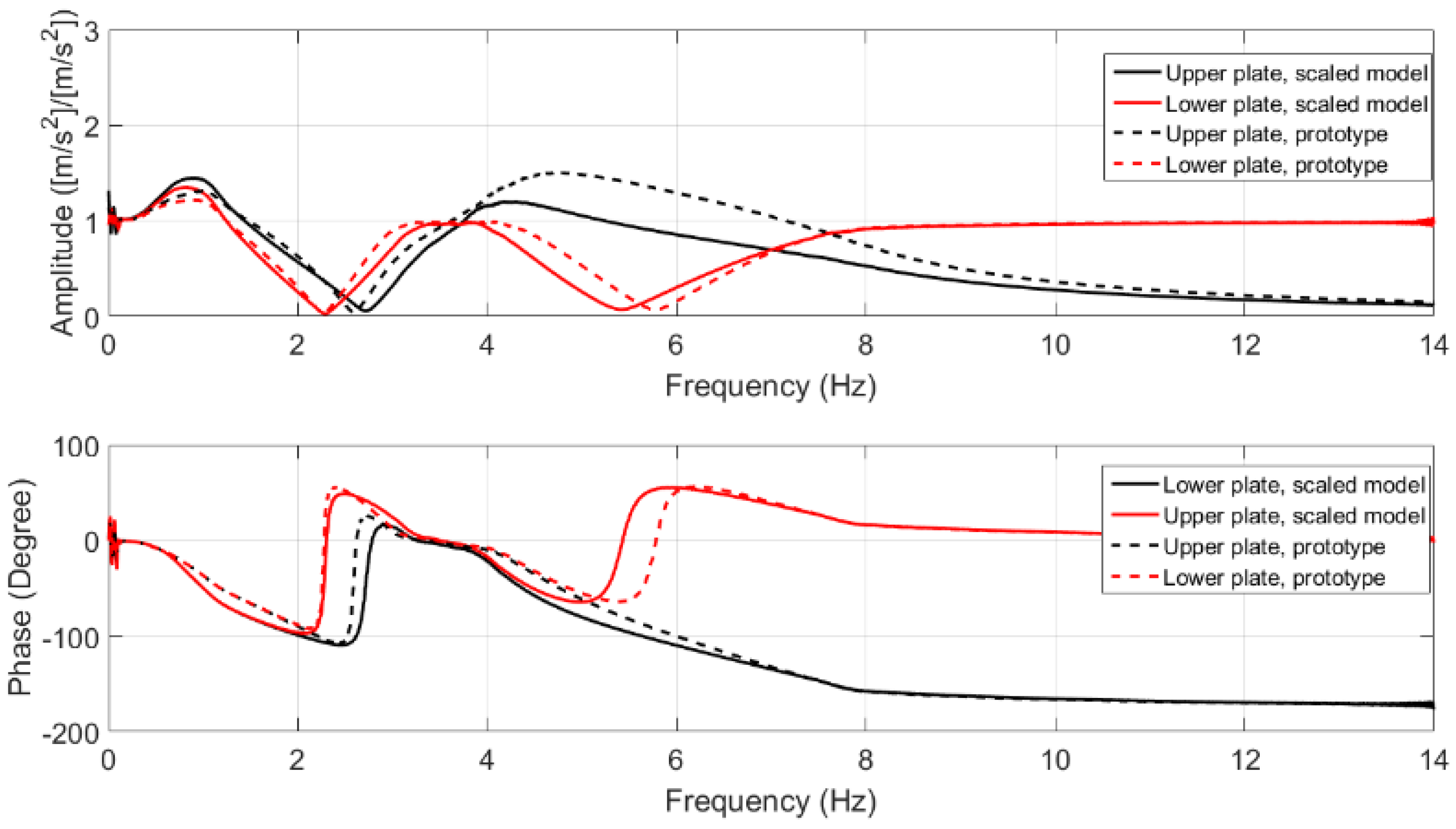
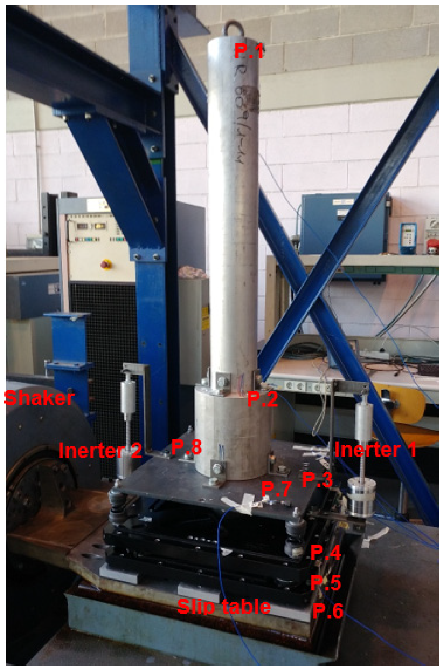
In order to evaluate the effects of various vibration control scenarios on the performance of the actual isolation system, a scaled structure is designed and manufactured. The scaled isolation system and structure has been designed based on the results of experiments, which are performed on a full-scale statue and its isolator in previous research (see [22]). The scaling factor is 1:3. This structure has similar dynamic behavior to the original one. The original isolator and a full-scale copy of the statue placed on a shaker are shown in Figure 1. The measurements points on the statue and the isolator have been shown in this figure. This isolation system was designed to isolate the statue from any kind of ground vibration and protect this valuable object against earthquakes. In order to obtain these requirements, an isolation system, which consists of two parts, is developed, as follows. First, a sliding part for the mitigation of the seismic vibrations; these low friction slides are equipped with devices to restore the statue to its initial position in case of displacement from the rest position. The second part consists of a vibration-mechanical filter, is placed on top of the sliding unit, made up of anti-vibration rubbers for isolating ground-borne vibrations generated by the underground trains. More details about this isolator and the experimental test can be found in [22]. Based on the experimental tests, a multibody model for the isolator is designed in ADAMS (a multibody dynamics simulation software). The models of the original structure and the scaled one are shown in Figure 2. Sweep sine excitation was used in the test of the original model. Frequency response functions between the ground plate and the head point (points P1 and P5 in Figure 1), and between the ground plate and the base (points P1 and P4 in Figure 1) are plotted in Figure 3. In addition, frequency response function (FRF) between the ground plate and the upper plate (points P1 and P3 in Figure 1), and FRF between the ground plate and the lower plate (points P1 and P2 in Figure 1) have been presented in Figure 4. This figures illustrate the good similarities in the dynamic response of the original and scaled models.
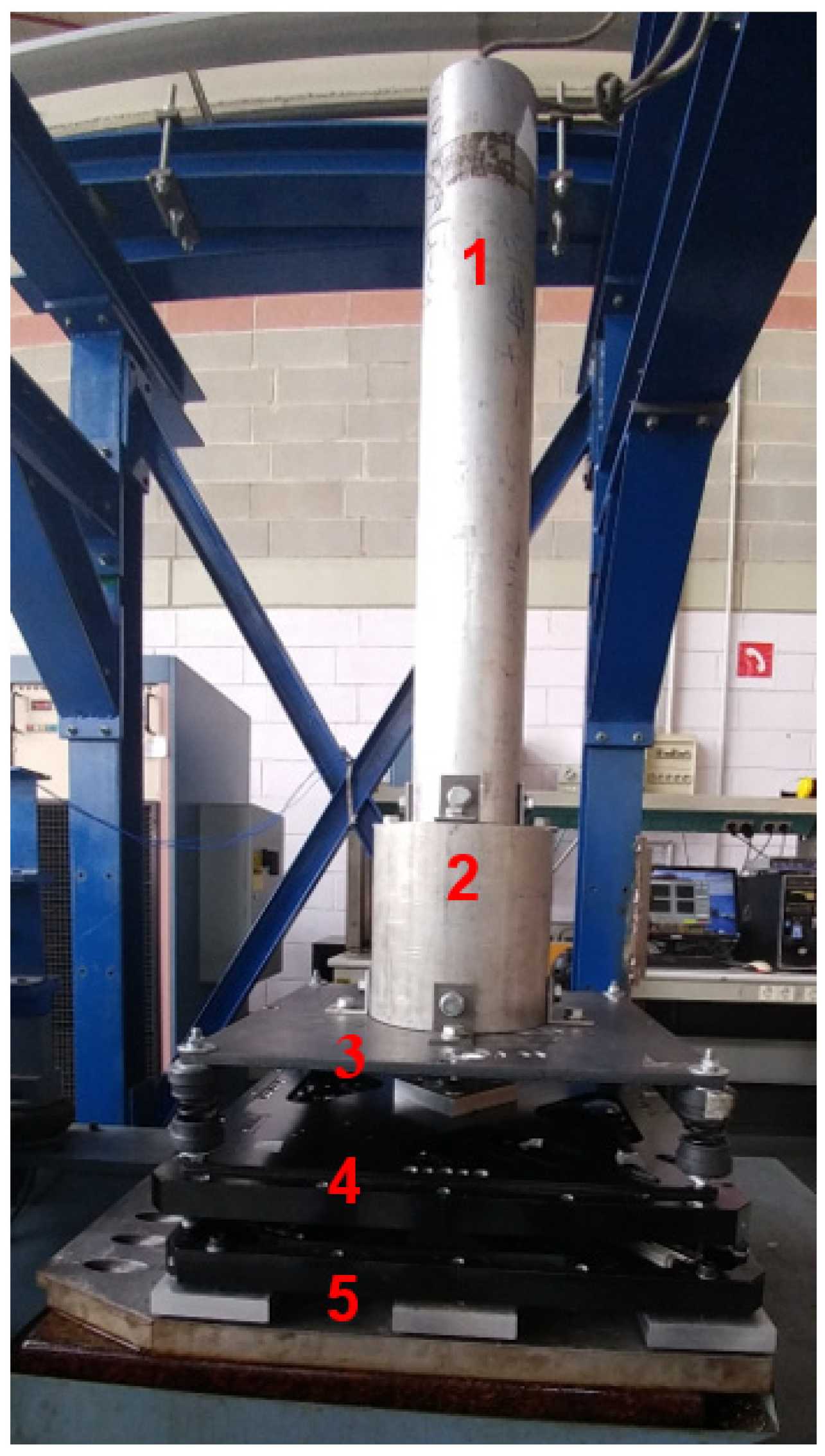
In the next step, this scaled model has been manufactured. Figure 5 shows this scaled isolation system. The main properties of this isolator are listed in Table 1. According to Figure 5, this scaled isolation system consists of different parts: (1) scaled statue, (2) base of statue, (3) upper plate, (4) lower plate (sliding unit), and (5) ground plate (connected to the slip table of shaker).
In addition, a screw-type inerter has been designed to improve the efficiency of the isolator. A schematic of the designed device can be found in Figure 6. The manufactured inerter has been presented in this figure. The force on two terminals of the device can be presented as
where () is inertance of the device, and are the acceleration of left and right terminals, respectively. The inertance of the device can be calculated as
where is the moment of inertia of the nut and flywheel along the centeral axis of the screw and is pitch size of the screw. Based on the size of pitch of the screw (4 mm) and the dimensions of the flywheel, the inertance of the device is around .
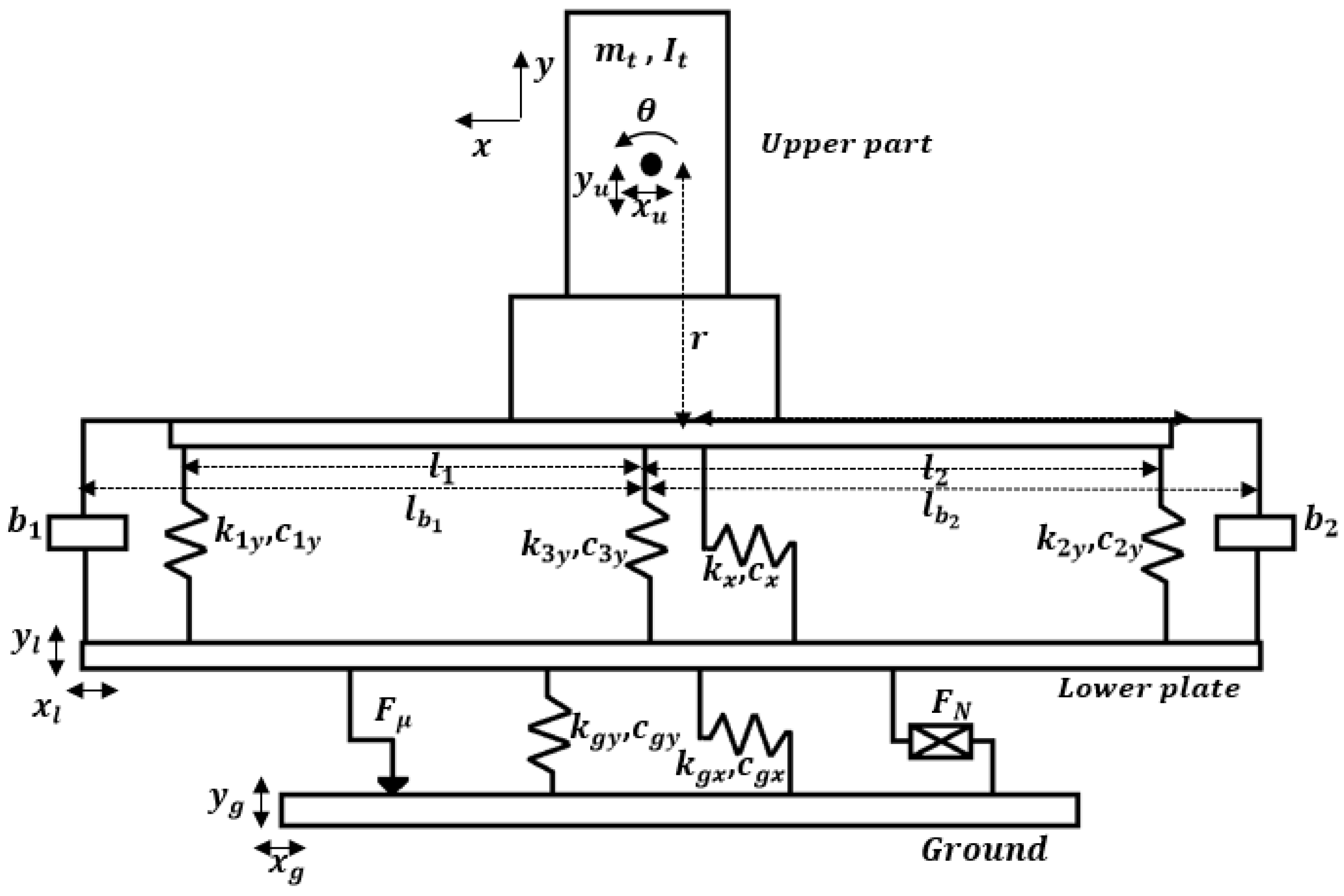
It should be noted that the MDOF model of the isolation system and the statue has been presented in [23]. Here, a brief description about this model equipped with two inerters in the vertical direction is presented. The 5DOF model of the scaled isolation system is presented in Figure 7. The general equation of motion for this model can be written as:
where , , and are mass, damping, and stiffness matrices, respectively; and, , and are the center of mass translation of the upper part along x and y directions and the rotation of the upper part around the center of mass center, respectively. In addition, and are the displacements of the lower plate in x and y directions, respectively. Disturbances that are transmitted from the ground to the lower plate are indicated by . Friction function between the ground plate and lower plate and the nonlinear dissipating force are presented by and , respectively. Details about the matrices and vectors can be found in [21,23]. Adding two inerters to the suspension system in the vertical direction changes the mass matrix of the system. The mass matrix of the system that is equipped with two inerters (see Figure 7) can be presented as:
where is the total mass of the upper part of the scaled isolator including the statue, the base and the upper plate, and is the moment of inertia of the upper part. The mass of the lower plate indicates by , , and are inertance of the inerters, and are distances in the x-direction between the points that the inrters have been attached to the upper plate from the center of mass of the upper part. The other matrices and vectors are similar to those that have been presented in Appendix. It should be noticed in Equation (3) that an ideal model has been considered for inerters. Normally, inerters have backlash and they will not work in all levels of vibrations or broad frequency range. Therefore, for a better prediction of the dynamic behavior of the isolation system, some effects, such as backlash and friction, should be considered for the added inerters to the isolator. In this research, we have just focused on the results of the experiments.
3. Experimental Results
According to the test setup that is presented in Figure 8, the response of the scaled structure without inerter and in the presence of inerter to a sweep sine excitation have been recorded. The frequency range of this signal is between 2 and 80 Hz. It should be noted the minimum frequency range for this electromagnetic shaker is around 2 Hz.
In order to obtain transfer functions between the ground plate and different points of the structure, the isolation system has been mounted on a slip table of an electromagnetic shaker. This layout has been shown in Figure 8. The isolator has been fixed on the slip table by using some adaptors, and then the table has been connected to the shaker. Based on the mentioned configuration, it is possible to apply different patterns of movement to the table in the horizontal direction. For performing the measurement, six accelerometers have been used with sensitivity that is equal to 100 mV/g. The block diagram of the measurement system of the test is presented in Figure 9.
The frequency response function between the measured point on the slip table (Point 6) and the head of statue (Point 1) has been presented in Figure 10 for two different cases. The frequency response function (FRF) of the original system (the scaled structure without inerter) and the structure equipped with two inerters has been shown in this figure. It can be observed in the case that we have two inerters between the upper and lower plates of the suspension system (see Figure 8), in the lower frequency range (between 2 and 4 Hz), the level of amplitude is less than the case that there is not any inerter in the suspension system. The maximum amplitude of FRF in the presence of two inerters reaches to 50 percent of the maximum amplitude of the original system in the frequency range under consideration. Therefore, this figure illustrates the effectiveness of the designed device in order to control the pitching motion of the slender structure. It should be noted the performance of the isolation system in higher frequency ranges has not changed. In addition, Figure 10 illustrates that the mechanical filtering effect of the suspension system in the presence of inerters is similar to the case without these devices. Due to the existence of backlashes in inerters and the connections, these two devices start to work only in the case that there is relatively high pitching motion on the upper part of the structure.
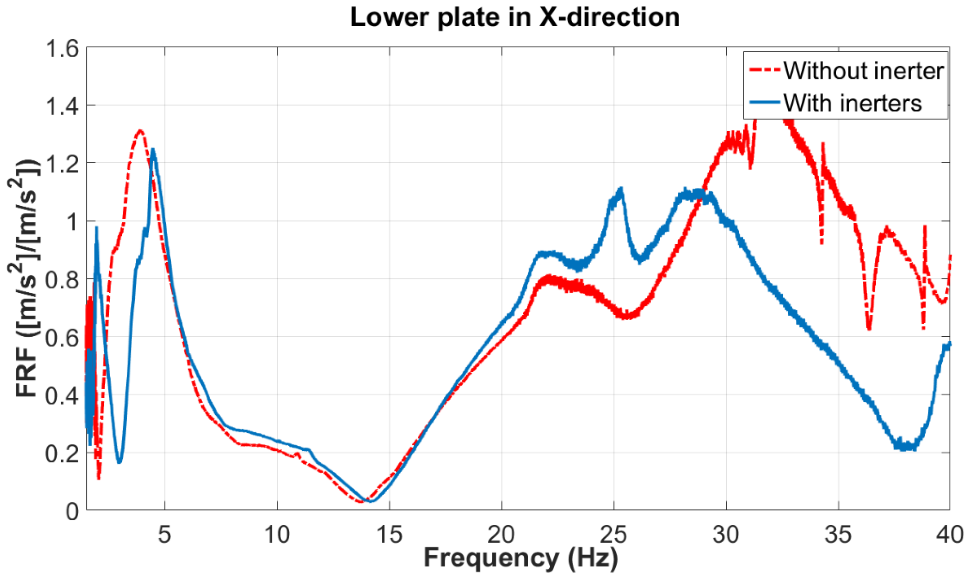
Furthermore, the FRF between the slip table and the point on the sliding unit (Point 4) has been plotted in Figure 11. It is observed that in the frequency range between 2 and 4 Hz, the presence of inerters can reduce the frequency band that the amplitude of the FRF is close to one. In fact, in this region, the sliding unit is moving with slip table and it cannot protect the slender structure. This phenomenon happens because, in this frequency range, the movement of cylindrical part (scaled statue) is so high and it performs as an energy absorber for the whole system. It is shown that by adding inerter and reducing the pitching motion of the upper part, the performance of seismic isolator improves, and it can slide in this frequency range.
4. Conclusions
In this research, a scaled structure has been designed and manufactured in order to evaluate the possible performance improvements for the isolation system of a famous statue. Based on the multibody model of the full-scale system (consists of statue and its isolator), a scale structure is designed and manufactured. According to the developed ADAMS model for this scaled isolator, FRFs in the horizontal direction have been compared with the FRFs that were obtained for the full-scale structure against the input that has been used in the experimental test. The comparison of FRFs of two models proved the good correlation between them. Furthermore, a type of ball-screw inerter has been designed and manufactured. The inerter as a passive device has been introduced to the manufactured scaled structure in order to reduce the vibration of the upper part in lower frequency ranges (2 Hz to 4 Hz). Accelerations on different points for the structure without inerter and equipped with two inerters have been measured in the presence of a sweep sine excitation. Based on the results of measurements, FRFs between the slip table and the head point, and also between the slip table and the point on the lower plate (sliding unit) were calculated. According to the FRFs that were obtained from the test, the effectiveness of the inerter to reduce the vibration of the slender structure (the scaled statue) has been illustrated. It should be noticed that, based on the design of the suspension system, ambient vibrations can be filtered out in a frequency range that is higher than 20 Hz. It should be mentioned that the backlash of the inerter could change the dynamic behavior of the system only in high amplitude vibration corresponding to the lower frequency range. Therefore, the suspension systems that are equipped with inerter have similar dynamic response in higher frequency ranges (above 5 Hz), and adding the inerters does not change the dynamic behavior of the suspension system in the high frequency range. According to this property, the modified isolation system can protect the valuable structure against earthquakes and ambient vibrations.
Author Contributions
H.R.K. and A.S. have proposed the control scheme and designed the device. A.C. and E.Z. have designed the experimental validation. The remaining part of the work has been done together.
Conflicts of Interest
The authors declare no conflict of interest.
Appendix A
State-space matrixes of the 5DOF model of the scaled isolator:
where
References
- Smith, M.C. Synthesis of mechanical networks: The inerter. IEEE Trans. Autom. Control 2002, 47, 1648–1662. [Google Scholar] [CrossRef]
- Smith, M.C. The Inerter Concept and Its Application. In Proceedings of the Society of Instrument and Control Engineers (SICE) Annual Conference, Fukui, Japan, 4 August 2003. [Google Scholar]
- Scheibe, F.; Smith, M.C. Analytical solutions for optimal ride comfort and tyre grip for passive vehicle suspensions. Veh. Syst. Dyn. 2009, 47, 1229–1252. [Google Scholar] [CrossRef]
- Wang, F.C.; Chan, H.A. Vehicle suspensions with a mechatronic network strut. Veh. Syst. Dyn. 2011, 49, 811–830. [Google Scholar] [CrossRef]
- Wang, F.C.; Hsieh, M.R.; Chen, H.J. Stability and performance analysis of a full-train system with inerters. Veh. Syst. Dyn. 2012, 50, 545–571. [Google Scholar] [CrossRef]
- Hu, Y.; Chen, M.Z.Q.; Shu, Z. Passive vehicle suspensions employing inerters with multiple performance requirements. J. Sound Vib. 2014, 333, 2212–2225. [Google Scholar] [CrossRef] [Green Version]
- Chen, M.Z.Q.; Hu, Y.; Li, C.; Chen, G. Semi-active suspension with semi-active inerter and semi-active damper. IFAC Proc. 2014, 47, 11225–11230. [Google Scholar] [CrossRef] [Green Version]
- Chen, M.Z.Q.; Hu, Y.; Huang, L.; Chen, G. Influence of inerter on natural frequencies of vibration systems. J. Sound Vib. 2014, 333, 1874–1887. [Google Scholar] [CrossRef] [Green Version]
- Hu, Y.; Chen, M.Z.Q. Performance evaluation for inerter-based dynamic vibration absorbers. Int. J. Mech. Sci. 2015, 99, 297–307. [Google Scholar] [CrossRef] [Green Version]
- Brzeski, P.; Pavlovskaia, E.; Kapitaniak, T.; Perlikowski, P. The application of inerter in tuned mass absorber. Int. J. Non-Linear Mech. 2015, 70, 20–29. [Google Scholar] [CrossRef]
- Marian, L.; Giaralis, A. Optimal design of a novel tuned mass-damper-inerter (TMDI) passive vibration control configuration for stochastically support-excited structural systems. Probab. Eng. Mech. 2014, 38, 156–164. [Google Scholar] [CrossRef]
- Li, P.; Lam, J.; Cheung, K.C. Control of vehicle suspension using an adaptive inerter. J. Automob. Eng. 2014, 229, 1934–1943. [Google Scholar] [CrossRef]
- Brzeski, P.; Kapitaniak, T.; Perlikowski, P. Novel type of tuned mass damper with inerter which enables changes of inertance. J. Sound Vib. 2015, 349, 56–66. [Google Scholar] [CrossRef]
- Shen, Y.; Chen, L.; Yang, X.; Shi, D.; Yang, J. Improved design of dynamic vibration absorber by using the inerter and its application in vehicle suspension. J. Sound Vib. 2016, 361, 148–158. [Google Scholar] [CrossRef]
- Brzeski, P.; Perlikowski, P. Effects of play and inerter nonlinearities on the performance of tuned mass damper. Nonlinear Dyn. 2017, 88, 1027–1041. [Google Scholar] [CrossRef]
- Sun, X.Q.; Chen, L.; Wang, S.H.; Zhang, X.L.; Yang, X.F. Performance investigation of vehicle suspension system with nonlinear ball-screw inerter. Int. J. Autom. Technol. 2016, 17, 399–408. [Google Scholar] [CrossRef]
- Chen, L.; Liu, C.; Liu, W.; Nie, J.; Shen, Y.; Chen, G. Network synthesis and parameter optimization for vehicle suspension with inerter. Adv. Mech. Eng. 2017, 9, 1–7. [Google Scholar] [CrossRef]
- Chen, H.; Su, W.; Wang, F. Modeling and analyses of a connected multi-car train system employing the inerter. Adv. Mech. Eng. 2017, 9, 1–13. [Google Scholar] [CrossRef]
- Hatzigeorgiou, G.D.; Pnevmatikos, N.G. Maximum damping forces for structures with viscous dampers under near-source earthquakes. Eng. Struct. 2014, 68, 1–13. [Google Scholar] [CrossRef]
- Siami, A.; Cigada, A.; Karimi, H.R.; Zappa, E.; Sabbioni, E. Using inerter-based isolator for passive vibration control of Michelangelo’s Rondanini Pietà. In Proceedings of the 20th World Congress of the International Federation of Automatic Control, Toulous, France, 9–14 July 2017. [Google Scholar]
- Siami, A.; Karimi, H.R.; Cigada, A.; Zappa, E.; Sabbioni, E. Parameter optimization of an inerter-based isolator for passive vibration control of Michelangelo’s Rondanini Pietà. Mech. Syst. Signal Process. 2018, 98, 667–683. [Google Scholar] [CrossRef]
- Cigada, A.; Sabbioni, E.; Siami, A.; Zappa, E. Modeling and Testing of the anti-vibration Base for Michelangelo’s Pietà Rondanini. In Proceedings of the International Modal Analysis Conference (IMAC), Orlando, FL, USA, 25–28 January 2016. [Google Scholar]
- Siami, A.; Cigada, A.; Karimi, H.R.; Zappa, E. Vibration protection of the famous statue against ambient and earthquake excitation using tuned-inerter-damper. Machines 2017, 5, 33. [Google Scholar] [CrossRef]
Figure 1.
Experimental setup, position of accelerometers and reference system.
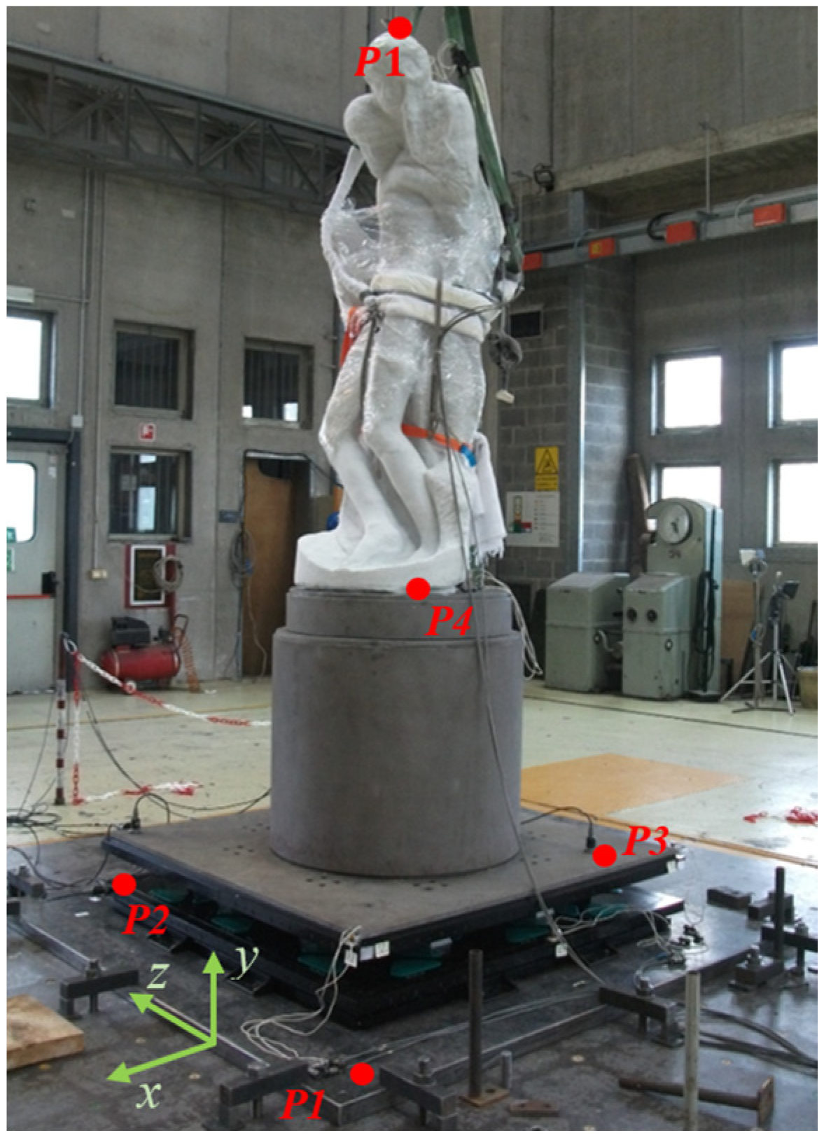
Figure 2.
A schematic plan of the multibody models; (a) the original isolator and statue, (b) the scaled model.
Figure 2.
A schematic plan of the multibody models; (a) the original isolator and statue, (b) the scaled model.
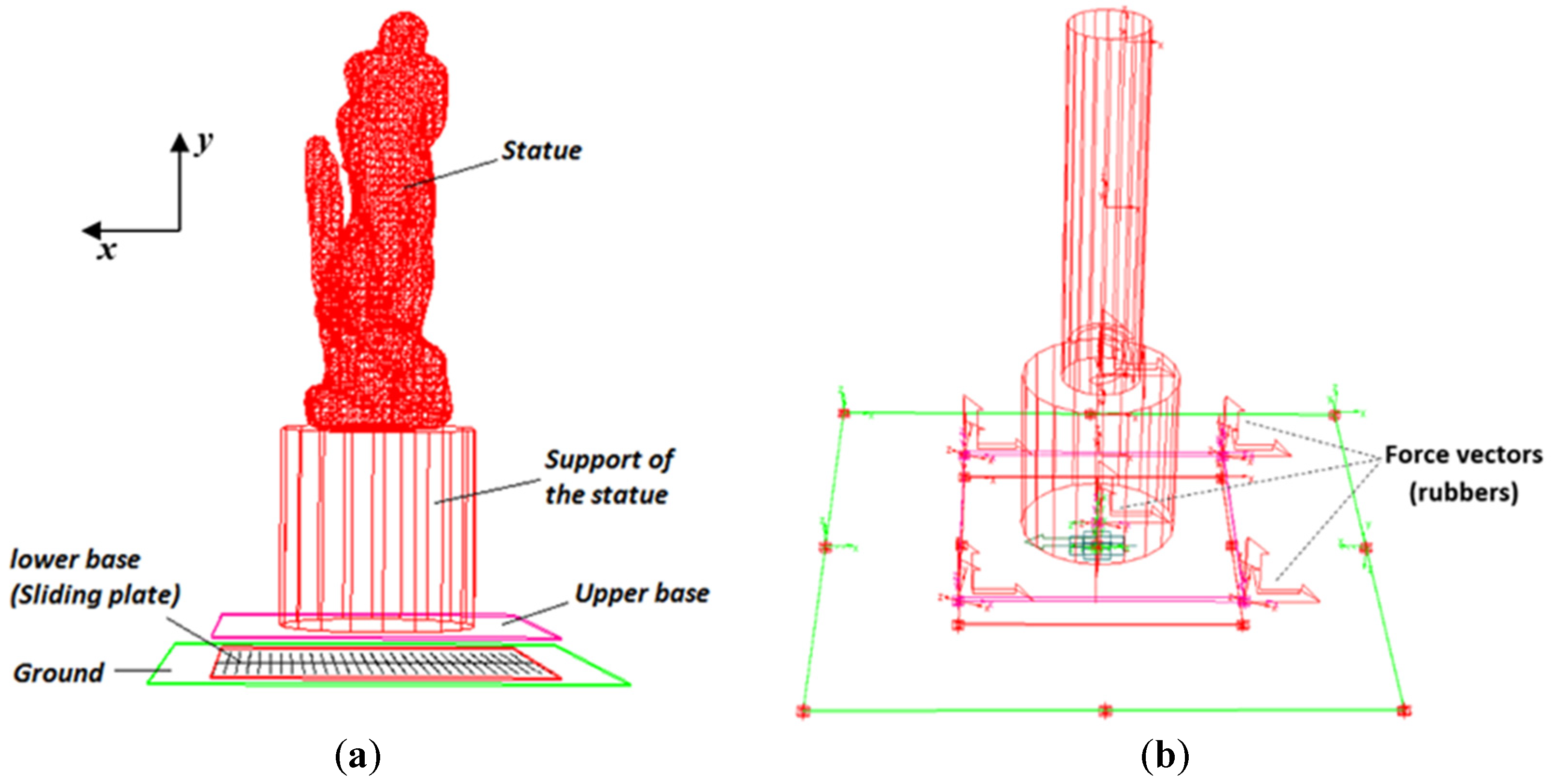
Figure 3.
A comparison of the scaled model with the prototype; frequency response function (FRFs) between the acceleration of the seismic base along the x direction and the accelerations of the head and base points.
Figure 3.
A comparison of the scaled model with the prototype; frequency response function (FRFs) between the acceleration of the seismic base along the x direction and the accelerations of the head and base points.

Figure 4.
A comparison of the scaled model with the prototype; FRFs between the acceleration of the seismic base along the x direction and the accelerations of the upper and lower plate points.
Figure 4.
A comparison of the scaled model with the prototype; FRFs between the acceleration of the seismic base along the x direction and the accelerations of the upper and lower plate points.

Figure 5.
The manufactured scaled structure.

Figure 6.
(a) Schematic of the designed ball-screw type inerter, and (b) the manufactured device.
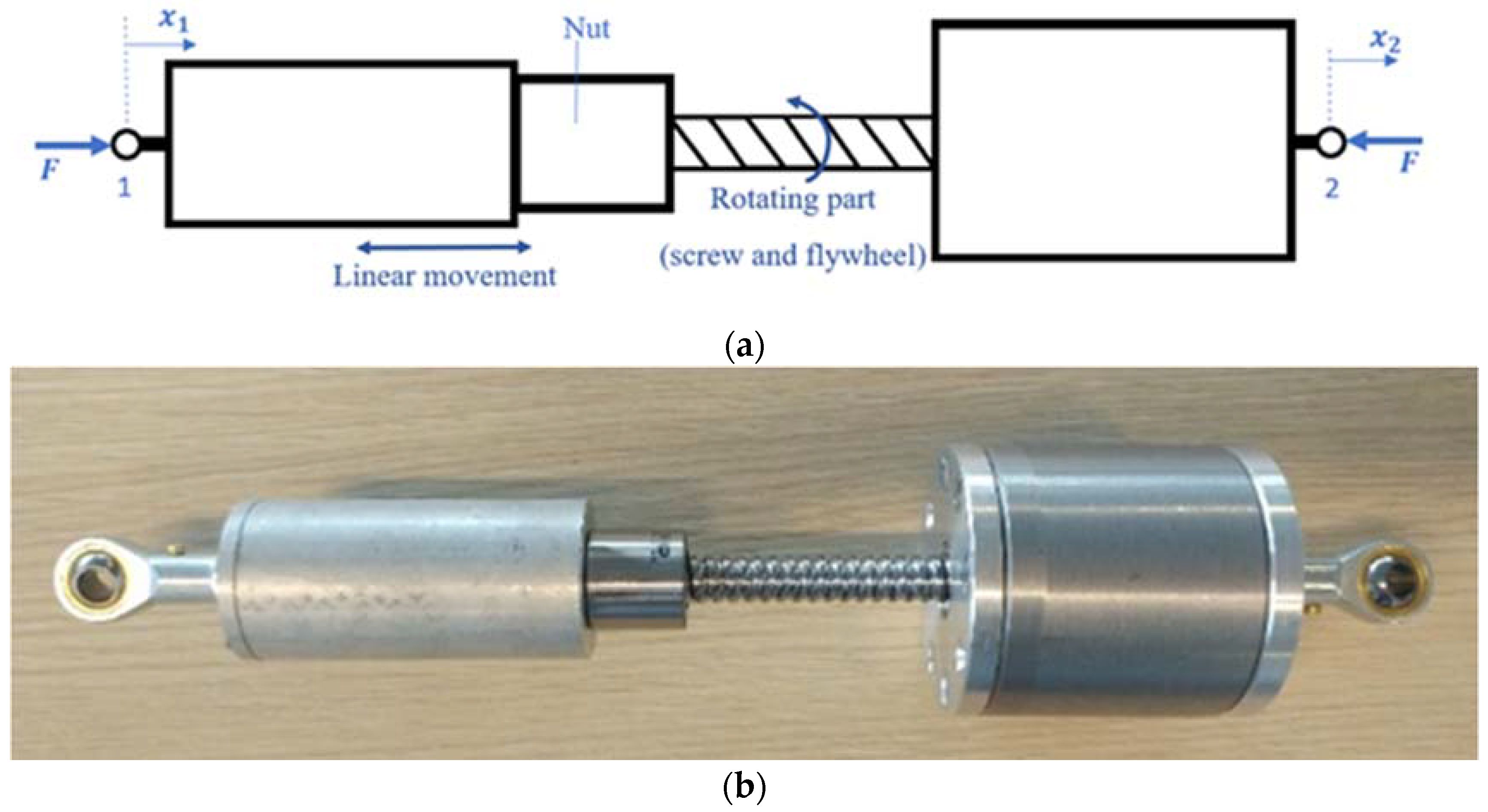
Figure 7.
The 5DOF model of the isolator equipped with two inerters.

Figure 8.
The configuration of accelerometers on the isolator.

Figure 9.
Block diagram of the measurement system of the experiment.
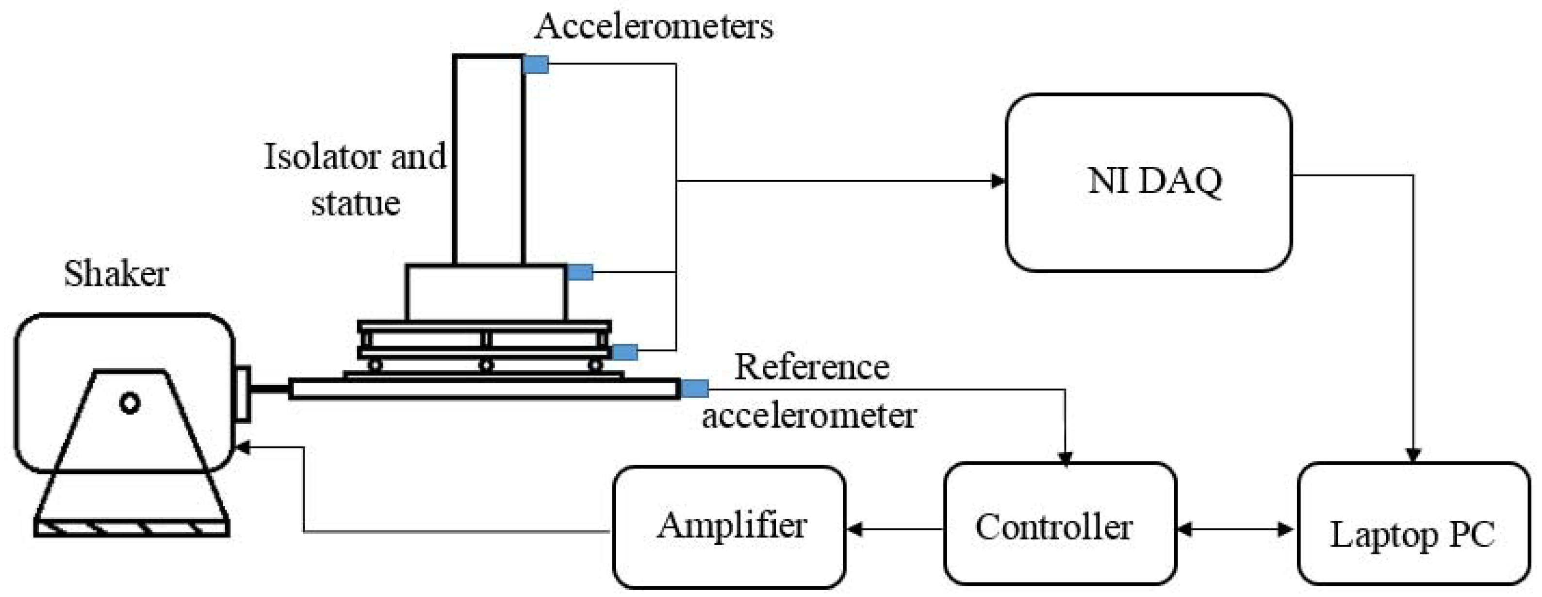
Figure 10.
FRF between the slip table and the head of statue.
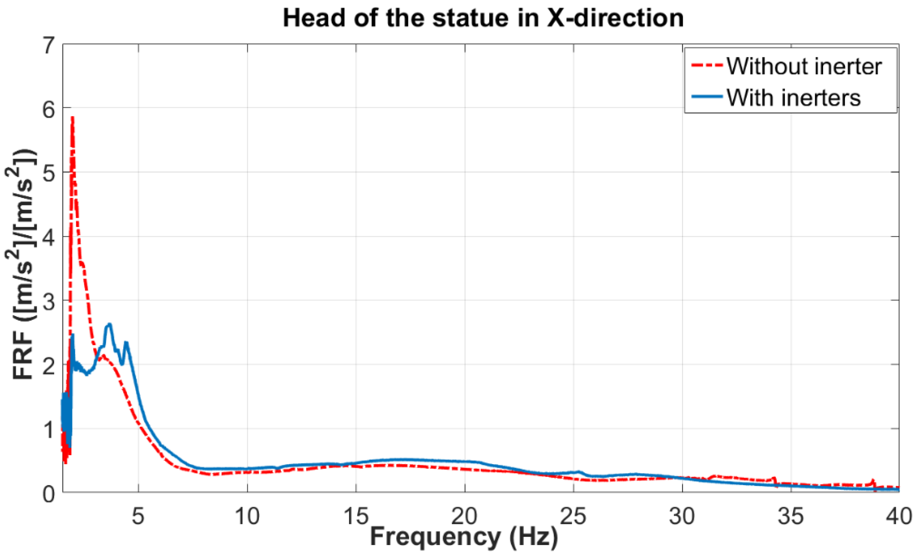
Figure 11.
FRF between the slip table and the lower plate.

Table 1.
Various properties of the manufactured scaled structure.
| Property | Values | |
|---|---|---|
| 1 | mass of the statue (kg) | 24.4 |
| 2 | mass of the base (kg) | 17.8 |
| 3 | mass of the upper plate (kg) | 15.8 |
| 4 | stiffness of corner spring in vertical direction (kN/m) | 16.4 |
| 5 | stiffness of corner spring in horizontal direction (kN/m) | 3.7 |
| 6 | stiffness of center spring in vertical direction (kN/m) | 207.8 |
| 7 | stiffness of center spring in horizontal direction (kN/m) | 46.5 |
| 8 | moment of inertia of the upper part along z-direction () | 7.9 |
| 9 | natural frequency of the suspension system in x-direction (Hz) | 5.15 |
| 10 | natural frequency of the suspension system in y-direction (Hz) | 9.53 |
© 2018 by the authors. Licensee MDPI, Basel, Switzerland. This article is an open access article distributed under the terms and conditions of the Creative Commons Attribution (CC BY) license (http://creativecommons.org/licenses/by/4.0/).
Share and Cite
MDPI and ACS Style
Siami, A.; Karimi, H.R.; Cigada, A.; Zappa, E. Experimental Analysis of Inerter-Based Suspension Systems for Slender Structures. Designs 2018, 2, 15. https://doi.org/10.3390/designs2020015
AMA Style
Siami A, Karimi HR, Cigada A, Zappa E. Experimental Analysis of Inerter-Based Suspension Systems for Slender Structures. Designs. 2018; 2(2):15. https://doi.org/10.3390/designs2020015
Chicago/Turabian StyleSiami, Ali, Hamid Reza Karimi, Alfredo Cigada, and Emanuele Zappa. 2018. "Experimental Analysis of Inerter-Based Suspension Systems for Slender Structures" Designs 2, no. 2: 15. https://doi.org/10.3390/designs2020015