Article

Characterization of Pig Vertebrae under Axial Compression Integrating Radiomic Techniques and Finite Element Analysis

by
Cristian A. Hernández-Salazar
,
Camilo E. Chamorro
and
Octavio A. González-Estrada
*
School of Mechanical Engineering, Universidad Industrial de Santander, Bucaramanga 680002, Colombia
*
Author to whom correspondence should be addressed.
Inventions 2024, 9(2), 36; https://doi.org/10.3390/inventions9020036
Submission received: 18 December 2023 / Revised: 24 February 2024 / Accepted: 28 February 2024 / Published: 28 March 2024

Abstract

:
The study of pig bones, due to their similarity with human tissues, has facilitated the development of technological tools that help in the diagnosis of diseases and injuries affecting the skeletal system. Radiomic techniques involving medical image segmentation, along with finite element analysis, enable the detailed study of bone damage, loss of density, and mechanical functionality, which is a significant advancement in personalized medicine. This study involves conducting experimental tests on L3–L6 pig vertebrae under axial loading conditions. The mechanical properties of these vertebrae are analyzed, and the maximum loads they can sustain within the elastic range are determined. Additionally, three-dimensional models are generated by segmenting computerized axial tomography (CAT) scans of the vertebrae. Digital shadows of the vertebrae are constructed by assigning an anisotropic material model to the segmented geometries. Then, finite element analysis is performed to evaluate the elastic characteristics, stress, and displacement. The findings from the experimental data are then compared to the numerical model, revealing a strong correlation with differences of less than 0.8% in elastic modulus and 1.53% in displacement. The proposed methodology offers valuable support in achieving more accurate medical outcomes, employing models that serve as a diagnostic reference. Moreover, accurate bone modeling using finite element analysis provides valuable information to understand how implants interact with the surrounding bone tissue. This information is useful in guiding the design and optimization of implants, enabling the creation of safer, more durable, and biocompatible medical devices that promote optimal osseointegration and healing in the patient.

1. Introduction

The spine plays a critical role in the physical condition of human beings as it is highly related to the nervous system. Deterioration of the spine can result in pain and loss of mobility. These symptoms can be triggered by a variety of diseases, e.g., bone metastasis associated with prostate cancer, and osteoporosis, which lead to a weakening of the bone structure and increase the risk of failure due to compression and low-energy fractures [1,2]. Addressing these diseases and monitoring their progression calls for an integrated approach combining concepts from mechanical engineering and medicine. This interdisciplinary methodology contributes to biomechanics, exploring the physical interactions of living organisms through various approaches, including physical tests and numerical methods [3,4]. Studies focusing on the mechanical aspects of the human lumbar spine have been proposed to aid in the treatment of degeneration processes and understanding the mechanical effects under compression [3].
Due to the challenges associated with accessing human anatomical components, such as ethical and legal issues, analyses have been carried out using bones from animals resembling humans [5]. For studies related to the spine, Busscher et al. [6] found that pigs aged between 4 to 6 months serve as a suitable alternative due to their similarity to the human spine of 72-year-old specimens in terms of size, shape, and function. Their resemblance to the human spine can be observed in their morphology and biomechanical properties, such as the number of vertebrae, the curvature, the disc height, and the stiffness. Moreover, they showed that the width and depth of the end-plates in the human spine increase more caudally, likely due to the upright posture, demanding relatively larger caudal vertebral bodies to balance higher longitudinal loads. Similar to humans, pigs possess trabecular-type bones that form a porous structure. This structural arrangement allows the vertebra to have a lower mass while supporting mechanical stresses and absorbing shocks [7,8,9]. Therefore, pig bones are often used as a surrogate for human bones in experimental and numerical studies of the spine.
Significant progress has been made in the biomechanical study of pig vertebrae in recent years [10]. Experimental tests, including axial and radial tests, have been employed to determine the material properties, which exhibit an anisotropic material behavior [11,12]. This characterization also allowed a comparative study of the various properties of porcine bones compared to humans and other species [13,14]. However, not only can experimental tests be utilized to characterize vertebrae, but in silico tests using numerical models have also become valuable. These numerical models offer ease of data interpretation and the ability to conduct more complex analyses [4,13]. In this context, radiomics is about obtaining data from diagnostic medical imaging for the accurate representation of biological tissues, and creating models adjusted to the profiles of individuals [15,16]. This approach enables the creation of 3D models from 2D images of bones obtained through techniques like magnetic resonance imaging (MRI) and computerized axial tomography (CAT) [17,18]. There is a wide variety of software to perform the segmentation process, some of which are more accurate than others [19,20]. One of the most widely used is the freely distributed 3D Slicer v 4.10 software [21], which provides tools to facilitate the segmentation process and improve the quality of the reconstructed solids [19,22].
The development of new models calibrated with real data, capable of accurately capturing the complex mechanical behavior of bone tissue, holds significant promise for addressing various issues related to bone health and diseases. The finite element method (FEM) is a numerical technique that has been used to create three-dimensional (3D) models that represent the physical behavior of porous materials such as bone tissues [23], rocks [24], cellular structures [25], and more. These models include appropriate boundary conditions and material models that account for the porosity, elasticity, plasticity, and fracture of the porous materials for accurate numerical representations [26]. These numerical models can then be compared to experimental studies that measure the mechanical response of the porous bone materials under various loadings and environmental conditions [27,28]. Proposed numerical models offer predictive capabilities for various tumor growth scenarios within vertebrae, serving as valuable clinical decision support tools [29]. In [30], a study was conducted using compression tests on healthy vertebrae, fractured vertebrae, and instrumented with transpendicular screws. This approach aimed to obtain the mechanical properties, such as stiffness, strength, and strain, of the different vertebrae conditions and compare them with the results obtained from a mechanical analysis using finite elements. Another work performed experimental compression tests on the cartilages between the L1–L2 vertebrae to determine stress–strain characteristics that reflect the viscoelastic behavior of the cartilages [31]. The results were then compared to the numerical values obtained from a finite element model, and close agreement was observed. These works demonstrate the usefulness and effectiveness of the FEM for modeling and analyzing the mechanical behavior of porous materials in different situations, such as biomedical, geotechnical, and structural applications.
Regarding implant design, research aims for improved biocompatibility and seamless integration into the intricate structure of bone tissue [32]. By refining materials and designs, the goal is to promote enhanced bone growth while mitigating the risk of rejection or associated complications from implanted devices [33]. Finite element modeling tailored to bone tissue dynamics plays a crucial role in iteratively designing and optimizing implants [34,35]. This approach enables thorough evaluations across critical parameters like load distribution and mechanical response, aiding in preemptively addressing potential complications such as fractures or implant loosening. Virtual testing allows a systematic evaluation and comparison of different implant options before real-world application, identifying optimal characteristics for enhanced integration and accelerated healing within the bone matrix. Furthermore, the customization afforded by finite element models ensures implants can align with each patient’s unique anatomical and mechanical characteristics, ultimately enhancing patient outcomes and reducing costs associated with extensive physical prototyping [36].
This paper presents a comprehensive analysis and comparison of the experimental data obtained from compression tests conducted on porcine L3–L6 vertebrae, with numerical models developed using finite element analysis. The objective of the study is to utilize radiomic techniques and finite element analysis to comprehensively assess pig vertebrae under axial loading conditions, aiming to advance personalized medicine, enhance accurate medical outcomes, and guide the design of safer and more biocompatible medical devices for optimal osseointegration. The entire work is systematically divided into three distinct stages, each contributing to the overall objective of the study. In the first stage, the primary focus is on the acquisition of experimental data. This is achieved through axial compression tests conducted on the vertebrae, following the guidelines and recommendations of previously conducted research in this field. The data obtained from these tests serve as a benchmark for evaluating the accuracy and reliability of the numerical models developed in the subsequent stages. The second stage involves the post-processing of diagnostic medical images. The vertebrae are segmented using the freely available software, 3D Slicer. This software is capable of generating STL files that accurately represent the bone tissues. These STL files serve as the basis for the development of the numerical models in the next stage. The use of 3D Slicer ensures that the models are an accurate representation of the actual bone tissues, thereby enhancing the reliability of the results obtained from the numerical models. In the third and final stage, the numerical model is created using finite elements. This model is designed to determine the elastic behavior of the model, taking into account its specific geometry and the anisotropic nature of the bone as a functionally graded material. The development of the numerical model involves a detailed analysis of the bone structure and the mechanical properties of the bone tissues. Once the numerical model is developed, the results obtained from the experimental compression tests, including the elastic moduli and displacements, are compared with those obtained from the numerical models. This comparison is carried out to demonstrate the similarity between the experimental and in silico results. The close correlation between the experimental and numerical results validates the accuracy of the numerical models, thereby demonstrating the effectiveness of finite element analysis in predicting the mechanical behavior of bone tissues.

2. Materials and Methods

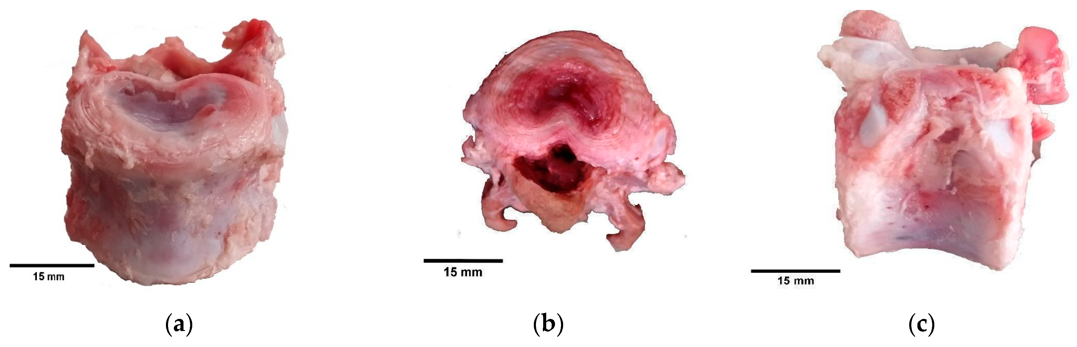
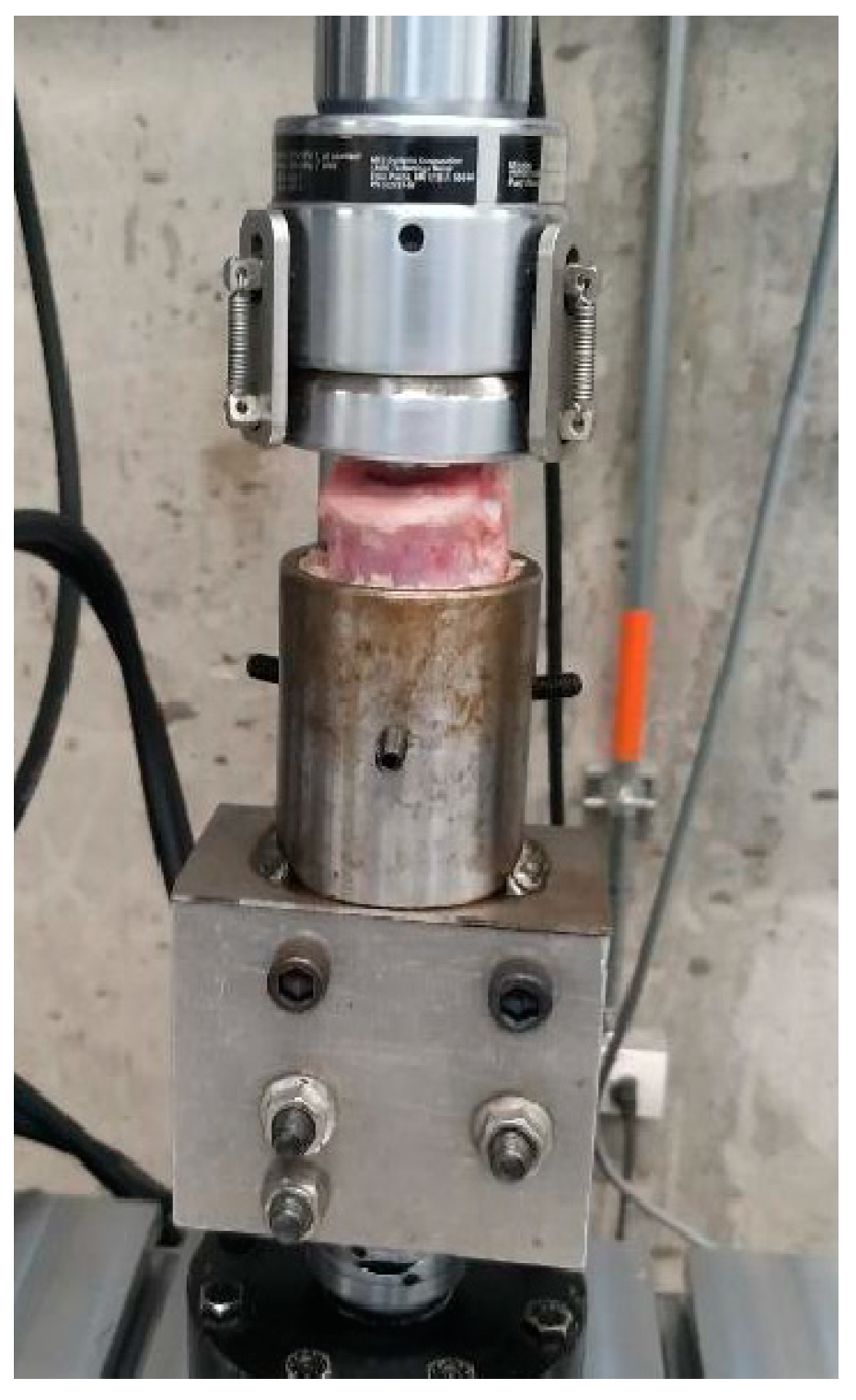
2.1. Compression Tests

The vertebrae were extracted from the spine of three healthy specimens of Piettrain Sus scrofa domesticus, with ages between five and six months [6]. The vertebrae are part of the lumbar section, from L3 to L6. The samples for the three specimens were prepared and visually inspected to confirm that they did not have infections, fractures, or wear. The experiment was carried out on the same day that the fresh bone was obtained to avoid poor refrigeration, which could affect its physical properties. Transport from the laboratory was facilitated by using a refrigerator kept at a constant temperature of 8 degrees Celsius. The vertebrae were cleaned, and the remains of muscle and soft tissues were removed with surgical instruments, in this case scalpels, reiterating each part with extreme care. The possibility of removing the soft tissues with heat was discarded since it modifies the physical properties of the bone. Figure 1 shows different views of the vertebra L4 for specimen 1. Table 1 shows the average measurement values of the height, width, and depth of the L3–L6 vertebrae belonging to the three back spines and the mass values for each sample.
The compression tests with loads normal to the transverse plane were performed on an MTS Bionix test machine [37], Figure 2, with a vertical displacement speed of 2 mm/min, measured by an LVDT (Linear Variable Differential Transformer). The force and displacement values of the vertebrae in the linear elastic zone were obtained. The consideration of linear elasticity for bone in the vertebra is a common and reasonable assumption in biomechanics studies. Linear elasticity is a simplifying assumption that implies a linear relationship between stress and strain, making the analysis more tractable mathematically. In many cases, bones exhibit linear elastic behavior within certain ranges of loading, particularly at low-to-moderate strain levels, where bone remodeling occurs. From the experimental test, the elastic modulus E for a linear elastic behavior was calculated using the constitutive relation σ = E ϵ , where σ is the compression stress, and ϵ is the Cauchy strain obtained from the ratio between the displacement to which the vertebrae were subjected and the initial length. The compression stress is obtained from the applied force F and the apparent area A a p , which varies for each vertebra and is calculated from the segmented images using:
σ = F A a p .

2.2. 3D Segmentation and Material Model

For the medical imaging, computerized axial tomography (CAT) scans of the spines were obtained using a Toshiba Aquilion 64 tomograph, with 12 slices/second contrast, a thickness of 0.5 mm, and 64 simultaneous detector rows. Imaging parameters include a resolution of 512 pixels by 512 pixels, with a bit depth of 16. A peak kilovoltage of 120 kV was used during the acquisition of the CT, with a data collection diameter of 500 mm. To define the numerical models, computerized axial tomography scans were performed on the set of spines. CATs were obtained in a DICOM format, and the 3D segmentations of each vertebra were reconstructed in an STL format using the 3D Slicer software [21].
Material properties, such as density and elastic modulus, were assigned considering a functionally graded material model using the Hounsfield scale. This approach is based on the fact that the bone is an organic material that exhibits changes in the elastic modulus, from areas characterized by bone with high elastic modulus to those with lower values. Thus, we define a finite element model that changes the elastic modulus of the elements based on the Hounsfield units (HU) measured in their spatial location of the CT scan. The HU has been correlated to the values of bone density and elastic modulus. The HU is not constant at the element level, thus, we consider an integrated average intensity value for the current element [38]. Information from available studies [39] was used to define the material model in the software Bonemat [38]. In Bonemat, both the mesh model and the DICOM file containing the Hounsfield scale (HU) are used for the purpose of fitting the equations and assigning the elastic modulus value element-wise in the mesh. The apparent density ρ [kg/m3] was adjusted to the specific range (1250–147) of the HU present in the bone tissues [23] for densities in the range (725–690) kg/m3, and coefficients of 0.0226 and 696.66 were obtained in (2) for a linear fitting:
ρ = 0.0226 H U + 696.66  
For each vertebra, the HU and apparent density values vary inside the bone, with a functionally graded structure typical of biological tissues. This suggests that the distribution of HU and bulk density values are not uniform throughout the bone, but varies in a graded or functional manner, which is characteristic of the structural complexity. Linear isotropic values of elastic modulus E [MPa], within the range (20–100) MPa, were also calculated element-wise using the information obtained from the CT scans and the apparent density from Equation (2). The expression reads:
E = 12,003,626.5 + 54,397.1 ρ
The final distribution of the elastic modulus for vertebra L5 in specimen 1 is shown in Figure 3a. Figure 3b shows the internal variation of the elastic modulus.

2.3. Finite Element Model

In the finite element method, we are interested in evaluating the displacement field, while considering a specified set of boundary conditions. Then, we can evaluate strain and stress fields during postprocessing. Let uhdenote the finite element approximation of displacements at point x , representing the calculated estimate for the displacement at that point. N i stands for the interpolation functions corresponding to node i, with I being the set of all nodes in the mesh, and u i being the value of the solution at node (i). Then, the approximation of displacements at a given point x is obtained from the contributions from all nodes in the mesh, weighted by their respective interpolation functions such that:
u h x = i I N i x u i
The solution is sought within a functional space V h V associated with a mesh of isoparametric finite elements of characteristic size h. This solution satisfies the condition that for all v V h , a ( u h , v ) = l v . Using a variational formulation of the elasticity problem and the finite element approximation u h = N u e , where N denotes the basis polynomial functions of second order, we obtain a system of linear equations to solve the displacements at nodes u e :
KU = f
Here, K is the stiffness matrix, U represents the vector of nodal displacements, and f is the load vector. The finite element analysis involves defining the analysis type, boundary conditions, material model, and mesh generation. Post-processing evaluates results, followed by an analysis of their implications. To ensure the reliability and accuracy of the analysis, a mesh independence test is conducted, verifying the convergence of displacement solutions. This iterative process ensures the robustness of the finite element method and the consistency of results, providing a comprehensive understanding of the studied phenomena.
A linear elastic model with a Galerkin-type finite element formulation was used to solve the problem under consideration. Once the 3D models of the vertebrae were available, the meshing of each segmentation was carried out, as shown in Figure 4. The numerical model is prepared in the software Ansys 2021R2 [38], defining a linear static structural analysis. During the compression test, the bone tissue experiences loading that is applied slowly or at a constant rate, and the response of the material is observed under this quasi-static condition. For a linear analysis, the displacements are solved under the following assumptions: The stiffness matrix K is essentially constant, such that the materials have linear elastic behavior and small deformations theory is used. The load vector f is statically applied, i.e., no time-varying forces are considered, and no inertial effects are included. Moreover, since vertebrae are characterized by trabecular bone tissue, the elastic modulus is assigned taking into account that its value is not uniform throughout its volume, thus having a lower elastic modulus in the central part of the vertebra and higher values in the parts close to the exterior [8].
A mesh composed of second-order tetrahedral elements was used, with 26,089 nodes and 16,896 elements. For mesh independence, Table 2 displays the convergence of the displacement solution with respect to the number of elements for h-adapted meshes, for a final variation of less than 0.1% in the last iteration, which indicates asymptotic range. It is noteworthy that all computer setups used for the computations were the same and the time taken for solving the finite element meshes was found to be minimal in this analysis. Quality control procedures for the mesh were put into place by confirming that each element has skewness values less than 0.95.
To evaluate the mechanical response of the numerical model, the elasticity problem involves Neumann and Dirichlet boundary conditions. For the Neumann condition, a remote load in the linear elastic range was applied, which is a type of load that is applied at a distance, rather than directly on the structure, to avoid stress concentration effects. In this case, a vertical axial load in the z-direction with a uniform value of 1000 N was applied remotely in the upper area of the vertebra. The choice of the load value was deliberate, not primarily because it represents a critical threshold, but rather due to its positioning within the elastic zone of the bone as depicted in Figure 5. The load of 1000 N is a value obtained from the experimental results that allows calibration to be carried out, and it is not the maximum value of the elastic zone. The use of a remote load can be beneficial in situations where it is difficult to apply a load directly to a structure or when the load is distributed over a large area. It allows for a more realistic simulation of the forces that the vertebra would experience in real-world conditions.
In addition to the remote load, Dirichlet boundary conditions were also imposed restricting displacements on the lower face of the vertebra, and preventing rigid body motion. This is crucial in ensuring the accuracy of the simulation, as these boundary conditions mimic the constraints that the vertebra would experience during the experimental tests. Furthermore, these boundary conditions replicate the compressive loads experienced within the body. These techniques, when combined, provide a comprehensive and realistic simulation of the mechanical behavior of the vertebra under load. This can be important in understanding the effects of various diseases on the spine, implant design, and in developing effective treatments.

3. Results and Discussion

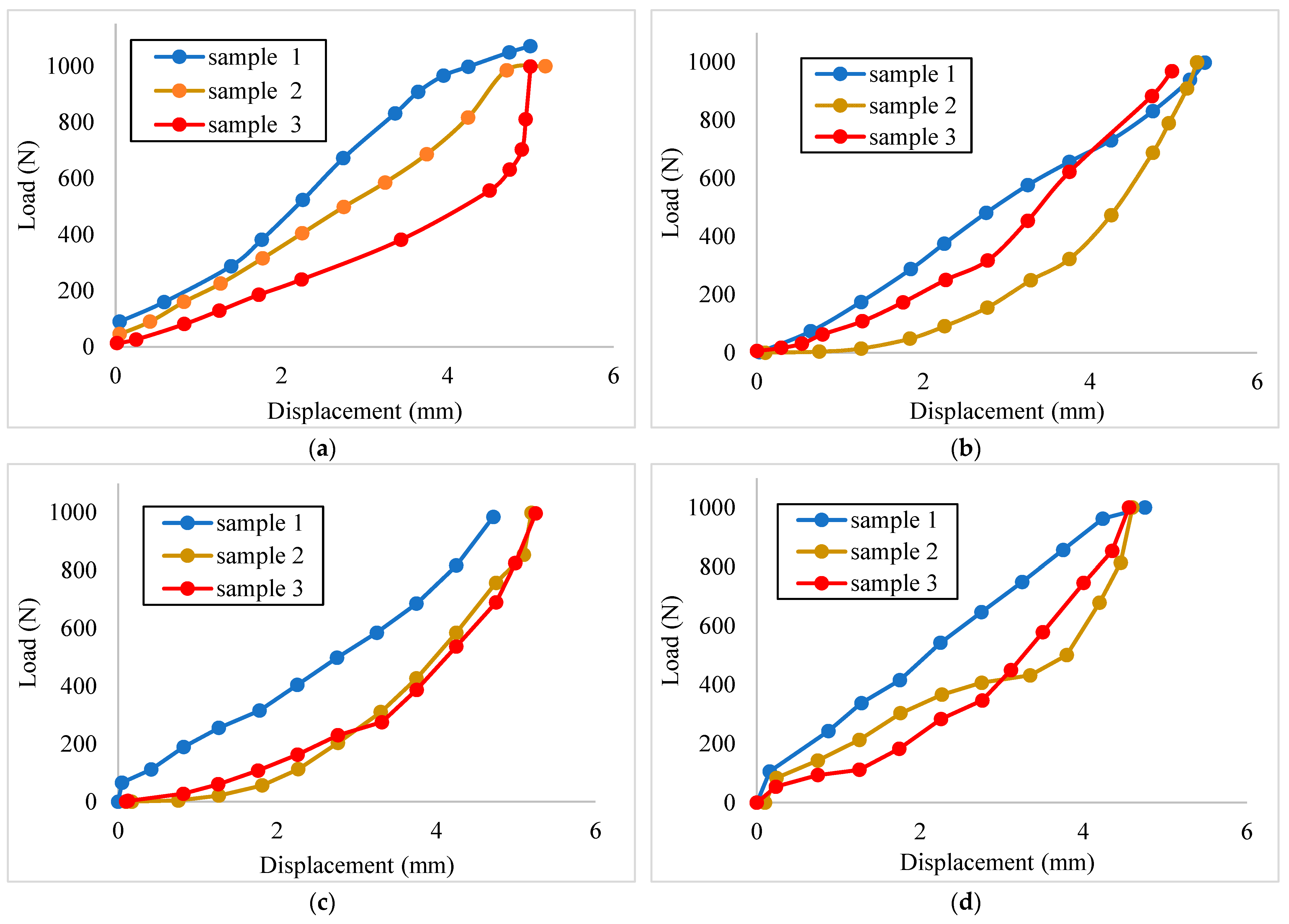
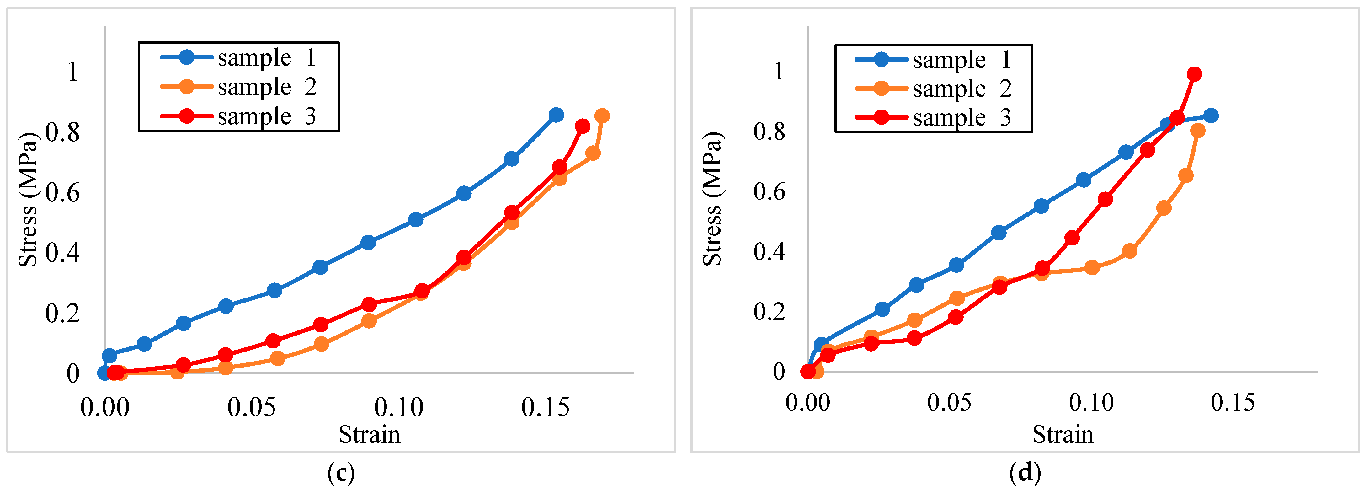
3.1. Compression Tests

Compression tests were performed on each of the vertebrae of the three spines. The output data were the applied force (N) and the displacement (mm). Figure 6 shows that the behavior between load and displacement is linearly related and was similar before reaching the pre-fracture magnitude. The compression test results resemble the results presented in the literature, where the value obtained for the maximum force applied to individual healthy vertebrae of the thoracolumbar region was 2.577 kN [30]. The displacements of the vertebrae with the applied force of 1000 N (it is not the elastic limit) vary between 4 mm and 5.5 mm, as shown in Table 3. Figure 7 shows the stress and strain relationship for vertebrae L3 to L5. The values of stress were calculated using the average cross-section of the vertebrae, and the strains were calculated using the average height for each set.

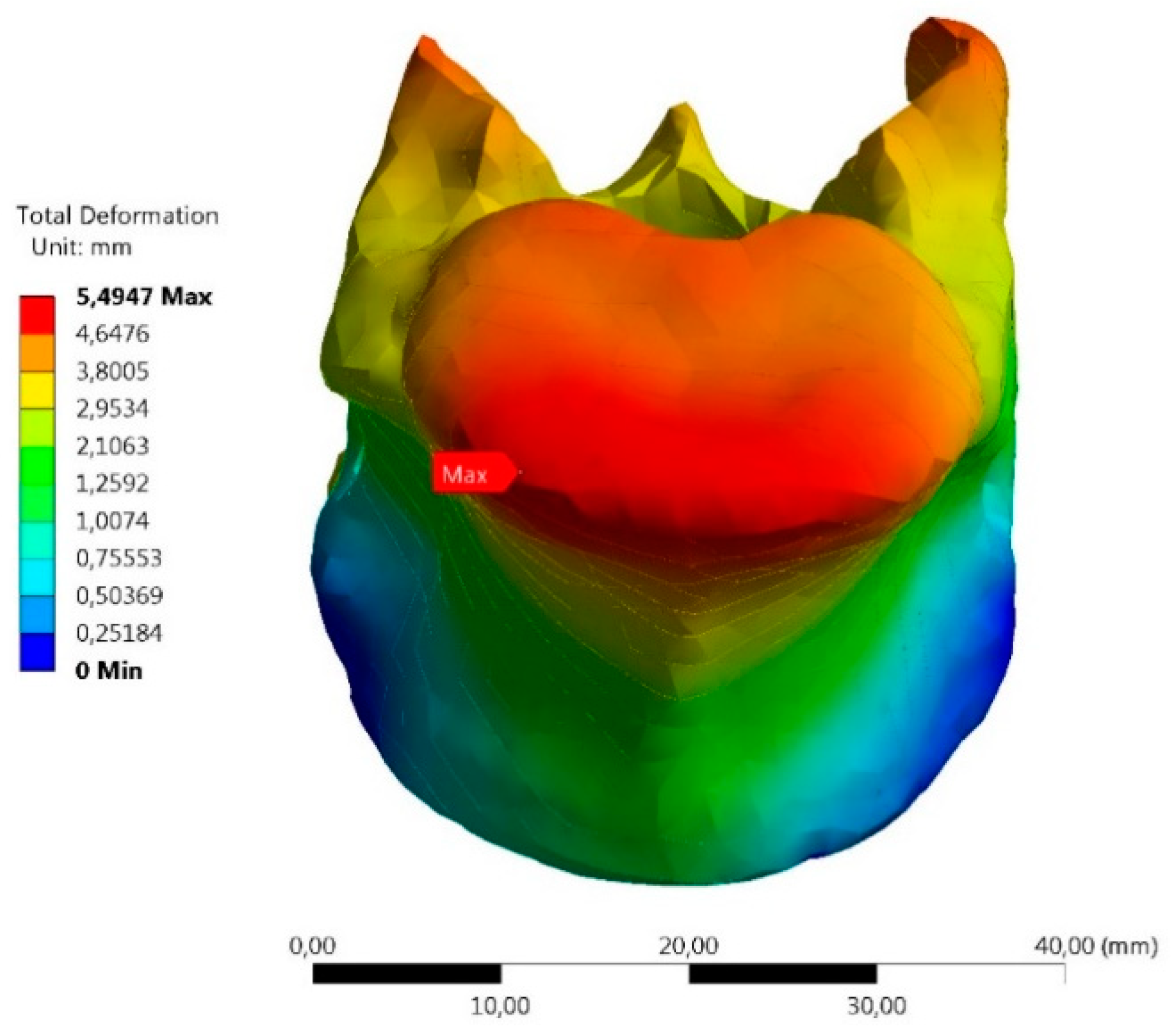
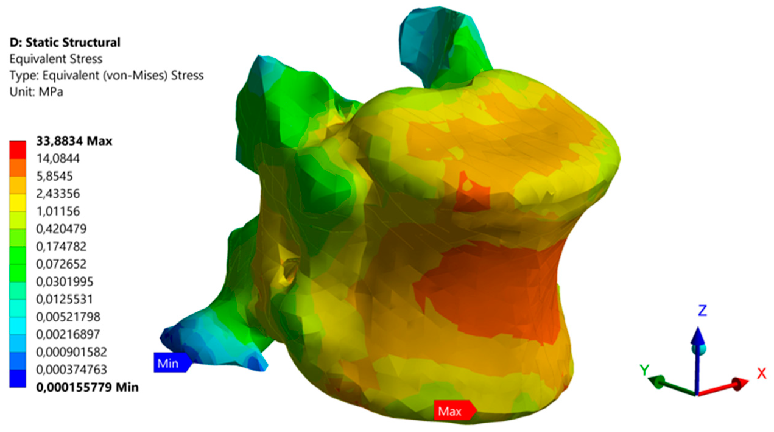
3.2. Numerical Model

For the finite element model, we applied a load of 1000 N to replicate the conditions of the experimental compression tests. In silico FEM tests yielded the elastic modulus, shown in Table 4. These results were compared with those calculated in the experimental tests for the same loading condition. Notice that both results present a maximum difference of 1.58% for the set of vertebrae studied. The values are similar to those obtained in the literature [40], where the elastic modulus was reported between 69 MPa and 81 MPa. The standard deviation indicates that the experimental elastic modulus and FEM values were in a similar range. The mechanical response of the porcine vertebrae agrees with the conditions of a cancellous bone. A difference is observed due to the size of the vertebrae analyzed since, in our study, they had a larger area.
Other factors that influence the results are the species of the pigs and their age, as well as the health and feeding conditions received [41]. Figure 8 shows the displacement of the L4 S1 porcine vertebra using the FEM model. The behavior of the vertebra is demonstrated for the load of 1000 N, resulting in 5.49 mm of displacement.
Figure 9 shows a section cut in the z-direction to observe the distribution of internal stresses, where the maximum value was 33.883 MPa. This value aligns with the optimal behavior of porcine vertebrae in the thoracolumbar area.
The results of the displacements obtained in the experimental tests and the FEM model were compared, as shown in Table 5. The minimum error values reflect a strong agreement between the two methods, thus highlighting the effectiveness of the use of digital models in representing the mechanical behavior of bone tissues. This is relevant in the context of bone biomechanics, as an accurate assessment of microstrains and stresses within bone tissue is crucial for bone characterization and implant design. Elevated strains can lead to microdamage and potentially inhibit remodeling, while lower strains are associated with bone resorption.

4. Conclusions

In this work, the mechanical properties of porcine vertebrae from L3 to L6 were characterized. Experimental axial compression tests were performed with loads within the elastic range, obtaining values for the elastic modulus of the different vertebrae between 50.07 MPa and 65.57 MPa, with maximum displacement values between 4.73 mm and 5.37 mm. Segmentation of computerized axial tomography scans of the porcine vertebrae was performed to obtain a 3D model of the bone tissue, considering an anisotropic material model with a density and elastic modulus variation using data from the Hounsfield scale. Finite element analysis was used to model the compression tests of the vertebrae, obtaining elastic moduli in a range of 49.53 MPa to 66.15 MPa and displacements between 4.68 mm and 5.35 mm, under the same boundary conditions as the experimental test. These values are significantly close to those obtained in the laboratory, which demonstrates the accuracy of the model in predicting the mechanical behavior of the vertebrae. Comparison of the experimental tests with the numerical models gave results with a difference of less than 0.8% in elastic modulus and 1.53% in displacement, indicating a good correlation.
The use of finite element analysis for accurate bone modeling provides an essential tool for understanding how bone interacts with mechanical loads, implants, or diseases. Improved modeling techniques could help better understand the biomechanical changes associated with osteoporosis, a condition characterized by decreased bone density and and increased risk of fractures. These models could aid in assessing fracture risk and developing more effective interventions to prevent fractures in individuals with osteoporosis. Moreover, accurate modeling of bone tissue mechanics is crucial for predicting fracture patterns, understanding fracture healing processes, and optimizing surgical interventions for fracture repair. Enhanced models could lead to improved fracture management strategies and better outcomes for patients recovering from bone fractures. Implants, biomaterials, and scaffolds can be designed to promote osseointegration by providing a rough, textured, or bioactive surface that facilitates bone growth on the implant with controlled microstrains. Modeling can help determine the shape and characteristics of these implants for better integration. Moreover, it can be used to identify areas of excessive stress that could lead to damage to the surrounding bone. They can be planned to distribute stresses more evenly and minimize points of concentrated stress, contributing to greater stability over time. This approach helps to optimize designs, predict biomechanical responses, and customize medical solutions, thus improving the quality of medical care. Furthermore, the use of finite element analysis in the design of implants allows for the creation of patient-specific models. These models can take into account the unique anatomical features of each patient, leading to implants that are tailored to the individual’s needs. This level of customization can improve the fit and function of the implant, leading to better patient outcomes. One significant contribution is the development of new models, calibrated with real data, capable of capturing and characterizing the complex mechanical behavior and accurately representing the results observed in the experimental compression tests. Further research on the development of digital twins for biological tissues is essential to seamlessly integrate radiomics and propel advancements in personalized medicine. In addition, the use of virtual testing and simulation in the design process can help to identify potential issues before the implant is manufactured. This can save time and resources by reducing the need for physical prototypes and iterative testing. By identifying and addressing potential issues early in the design process, the overall quality and performance of the implant can be improved.
To enhance the accuracy of the model, it is recommended to increase the number of samples undergoing laboratory tests and explore variations among different populations for a more comprehensive understanding of the mechanical properties. In addition, we plan to investigate the effects of bone diseases in order to determine how they affect physical behavior. Age and other bone characteristics also play a role since they were purchased from a nearby butcher shop and are trade animals that are kept in the enclosure until a certain age. Despite the small sample size in this specific study, our proposed methodology demonstrates a strong correlation between experimental and numerical results, with minimal differences in elastic modulus and displacement. Further improvements could also include the use of a tomograph with better resolution to increase the accuracy of the segmentation.

Author Contributions

Conceptualization, O.A.G.-E.; Formal analysis, C.A.H.-S. and O.A.G.-E.; Funding acquisition, O.A.G.-E.; Investigation, C.A.H.-S. and C.E.C.; Methodology, C.A.H.-S., C.E.C. and O.A.G.-E.; Project administration, O.A.G.-E.; Resources, O.A.G.-E.; Software, C.A.H.-S. and C.E.C.; Validation, O.A.G.-E.; Writing—original draft, C.A.H.-S. and C.E.C.; Writing—review & editing, O.A.G.-E. All authors have read and agreed to the published version of the manuscript.

Funding

This work was supported by Universidad Industrial de Santander (Grant numbers VIE 2522, VIE 3716).

Institutional Review Board Statement

The study was conducted according to the guidelines of the Declaration of Helsinki, and approved by the Ethics Committee of Industrial University of Santander (Act 18, 18 October 2019).

Data Availability Statement

The data presented in this study are available on request from the corresponding author.

Conflicts of Interest

The authors declare no conflicts of interest.

References

  1. Quiroz-Munoz, M.; Izadmehr, S.; Arumugam, D.; Wong, B.; Kirschenbaum, A.; Levine, A.C. Mechanisms of Osteoblastic Bone Metastasis in Prostate Cancer: Role of Prostatic Acid Phosphatase. J. Endocr. Soc. 2019, 3, 655–664. [Google Scholar] [CrossRef] [PubMed]
  2. Cunha, M.R.; Santos, A.R., Jr.; Petinari, L.; Goissis, G.; Nonaka, K.O.; Wang, C.C.; Genari, S.C. Characterization of the physical and mechanical properties of femoral bone defects filled with polyanionic collagen scaffolds in ovariectomized rats. Mater. Res. 2010, 13, 239–244. [Google Scholar] [CrossRef]
  3. Kurutz, M.; Oroszvry, L. Finite Element Modeling and Simulation of Healthy and Degenerated Human Lumbar Spine. In Finite Element Analysis—From Biomedical Applications to Industrial Developments; IntechOpen: London, UK, 2012. [Google Scholar] [CrossRef]
  4. Mirzaali, M.J.; Libonati, F.; Ferrario, D.; Rinaudo, L.; Messina, C.; Ulivieri, F.M.; Cesana, B.M.; Strano, M.; Vergani, L. Determinants of bone damage: An ex-vivo study on porcine vertebrae. PLoS ONE 2018, 13, e0202210. [Google Scholar] [CrossRef] [PubMed]
  5. Alini, M.; Eisenstein, S.M.; Ito, K.; Little, C.; Kettler, A.A.; Masuda, K.; Melrose, J.; Ralphs, J.; Stokes, I.; Wilke, H.J. Are animal models useful for studying human disc disorders/degeneration? Eur. Spine J. 2007, 17, 2–19. [Google Scholar] [CrossRef] [PubMed]
  6. Busscher, I.; Ploegmakers, J.J.W.; Verkerke, G.J.; Veldhuizen, A.G. Comparative anatomical dimensions of the complete human and porcine spine. Eur. Spine J. 2010, 19, 1104–1114. [Google Scholar] [CrossRef] [PubMed]
  7. Rodríguez-Cañizo, R.G.; Fuerte-Hernández, A.; Urriolagoitia-Sosa, G.; Merchán-Cruz, E.A.; Niño-Suárez, P.A.; Gónzalez-Rebatu, A. Determination of the mechanical properties of anterior column units and functional spinal units of the L3-L4 lumbar porcine segment. DYNA 2014, 81, 115. [Google Scholar] [CrossRef]
  8. Coombs, D.; Rao, M.; Bushelow, M.; Deacy, J. Simulation of lumbar spine biomechanics using Abaqus. In Proceedings of the 2011 SIMULIA Customer Conference, Barcelona, Spain, 17–19 May 2011; pp. 1–14. [Google Scholar]
  9. Borah, B.; Dufresne, T.E.; Cockman, M.D.; Gross, G.J.; Sod, E.W.; Myers, W.R.; Combs, K.S.; Higgins, R.E.; Pierce, S.A.; Stevens, M.L. Evaluation of Changes in Trabecular Bone Architecture and Mechanical Properties of Minipig Vertebrae by Three-Dimensional Magnetic Resonance Microimaging and Finite Element Modeling. J. Bone Miner. Res. 2000, 15, 1786–1797. [Google Scholar] [CrossRef] [PubMed]
  10. Sheng, S.-R.; Xu, H.-Z.; Wang, Y.-L.; Zhu, Q.-A.; Mao, F.-M.; Lin, Y.; Wang, X.-Y. Comparison of Cervical Spine Anatomy in Calves, Pigs and Humans. PLoS ONE 2016, 11, e0148610. [Google Scholar] [CrossRef] [PubMed]
  11. Li, Z.; Wang, G.; Ji, C.; Jiang, J.; Wang, J.; Wang, J. Characterization of the mechanical properties for cranial bones of 8-week-old piglets: The effect of strain rate and region. Biomech. Model. Mechanobiol. 2019, 18, 1697–1707. [Google Scholar] [CrossRef] [PubMed]
  12. Li, Z.; Wang, J.; Song, G.; Ji, C.; Han, X. Anisotropic and strain rate-dependent mechanical properties and constitutive modeling of the cancellous bone from piglet cervical vertebrae. Comput. Methods Programs Biomed. 2019, 188, 105279. [Google Scholar] [CrossRef] [PubMed]
  13. Hernandez, A.F.; Gustavo, R.; Urriolagoitia, G. Caracterización de Vértebras Porcinas Para su uso en Aplicaciones Biome-Cánicas; SEPI ESIME UA IPN: Azcapotzalco, México, 2010. [Google Scholar]
  14. Dahmen, T.; Roland, M.; Tjardes, T.; Bouillon, B.; Slusallek, P.; Diebels, S. An automated workflow for the biomechanical simulation of a tibia with implant using computed tomography and the finite element method. Comput. Math. Appl. 2015, 70, 903–916. [Google Scholar] [CrossRef]
  15. An, P.; Liu, J.; Yu, M.; Wang, J.; Wang, Z. Predicting mixed venous oxygen saturation (SvO2) impairment in COPD patients using clinical-CT radiomics data: A preliminary study. Technol. Health Care 2023, preprint. [Google Scholar] [CrossRef]
  16. Le, V.H.; Minh, T.N.T.; Kha, Q.H.; Le, N.Q.K. A transfer learning approach on MRI-based radiomics signature for overall survival prediction of low-grade and high-grade gliomas. Med Biol. Eng. Comput. 2023, 61, 2699–2712. [Google Scholar] [CrossRef] [PubMed]
  17. Gutiérrez, R.A.G. Biomechanical Study of Intervertebral Disc Degeneration. Ph.D. Thesis, Universitat Politècnica de Catalunya, Barcelona, Spain, 2013. [Google Scholar]
  18. Yang, T.; Zhang, C.Q.; Liu, Q.; Li, K. The rule of strain in different stratification of the intervertebral disc under physio-logic loading. Biomed. Res. 2017, 28, 987–994. [Google Scholar]
  19. Argüello, D.; Acevedo, H.G.S.; A González-Estrada, O. Comparison of segmentation tools for structural analysis of bone tissues by finite elements. J. Phys. Conf. Ser. 2019, 1386, 12113. [Google Scholar] [CrossRef]
  20. Hui, Y.; Wu, J.-S.; Yu, B.; Zhang, C.; Du, J. Construction of Biological Model of Human Lumbar and Analysis of its Mechanical Properties. Int. J. Pattern Recognit. Artif. Intell. 2018, 32, 1857002. [Google Scholar] [CrossRef]
  21. Fedorov, A.; Beichel, R.; Kalpathy-Cramer, J.; Finet, J.; Fillion-Robin, J.-C.; Pujol, S.; Bauer, C.; Jennings, D.; Fennessy, F.; Sonka, M.; et al. 3D Slicer as an image computing platform for the Quantitative Imaging Network. Magn. Reson. Imaging 2012, 30, 1323–1341. [Google Scholar] [CrossRef]
  22. Teo, J.C.; Si-Hoe, K.M.; Keh, J.E.; Teoh, S.H. Relationship between CT intensity, micro-architecture and mechanical properties of porcine vertebral cancellous bone. Clin. Biomech. 2006, 21, 235–244. [Google Scholar] [CrossRef] [PubMed]
  23. Parra, S.A.A.; Acevedo, H.G.S.; Estrada, O.A.G. Evaluation of damage to the lumbar spine vertebrae L5 by finite element analysis. Respuestas 2019, 24, 50–55. [Google Scholar] [CrossRef]
  24. Rivero-Méndez, S.D.; Ordoñez-Martínez, J.D.; Díaz, C.S.C.; Mantilla-Hernández, H.D.; González-Estrada, O.A. Caracterización de propiedades elásticas en una muestra de roca tipo arenisca mediante elementos finitos. Rev. UIS Ing. 2022, 21, 211–222. [Google Scholar] [CrossRef]
  25. Leon-Becerra, J.; González-Estrada, O.A.; Sánchez-Acevedo, H. Comparison of Models to Predict Mechanical Properties of FR-AM Composites and a Fractographical Study. Polymers 2022, 14, 3546. [Google Scholar] [CrossRef] [PubMed]
  26. Maldonado, J.A.; Puentes, D.A.; Quintero, I.D.; González-Estrada, O.A.; Villegas, D.F. Image-Based Numerical Analysis for Isolated Type II SLAP Lesions in Shoulder Abduction and External Rotation. Diagnostics 2023, 13, 1819. [Google Scholar] [CrossRef] [PubMed]
  27. Campos-López, J.P.; Fuerte-Hernández, A.; Hernández-Gómez, L.H.; Martínez-García, A.; Beltrán-Fernández, J.A.; Urriolagoitia-Calderón, G. Determination of the Mechanical Properties of Lumbar Porcine Vertebrae with 2D Digital Image Correlation. J. Appl. Biomater. Funct. Mater. 2015, 13, 195–200. [Google Scholar] [CrossRef] [PubMed]
  28. Bahia, M.T.; Mercuri, E.G.F.; Hecke, M.B. FE bone structural analysis with CT mapping of inhomogeneous material properties. In Proceedings of the ECCOMAS Congress 2016—7th European Congress on Computational Methods in Applied Sciences and Engineering, Crete Island, Greece, 5–10 June 2016; pp. 6574–6587. [Google Scholar] [CrossRef]
  29. Garcia-Andrés, X.; Nadal, E.; Arana, E.; Gandía-Vañó, B.; Ródenas, J.J. Methodology for the assessment of the risk of failure of metastatic vertebrae through ROM-based patient-specific simulations. Comput. Struct. 2024, 296, 107298. [Google Scholar] [CrossRef]
  30. Atanacio, O.; Avalos, N.; Barba, M.S.; Agón Rendón, M.; García-gonzález, A.; Jiménez, J.M.; Fuentes, R.Q. Caracterización de esfuerzos mecánicos en vértebras toracolumbares porcinas instrumentadas con tornillos transpendiculares. In Memorias del XXXVII Congreso Nacional de Ingeniería Biomédica; Sociedad Mexicana de Ingeniería Biomédica A.C.: Puerto Vallarta, Mexico, 2014; pp. 142–145. [Google Scholar]
  31. Azarnoosh, M.; Stoffel, M.; Markert, B. A study of the damage behaviour of porcine intervertebral discs in a bioreactor environment. J. Mech. Behav. Biomed. Mater. 2017, 77, 727–733. [Google Scholar] [CrossRef]
  32. Corredor, E.; González-Estrada, O.A.; Ospina-Ospina, R. Deposición de láser pulsado de hidroxiapatita en Ti-6Al-4V producido por manufactura aditiva. Rev. UIS Ing. 2022, 21, 107–122. [Google Scholar] [CrossRef]
  33. Agarwalla, S.V.; Solomon, A.P.; Neelakantan, P.; Rosa, V. Novel materials and therapeutic strategies against the infection of implants. Emergent Mater. 2020, 3, 545–557. [Google Scholar] [CrossRef]
  34. Reboledo-Grau, D.; Martínez-Bordes, G. Metodología para el diseño computacional de andamios a ser utilizados en reparación ósea. Rev. UIS Ing. 2020, 19, 301–314. [Google Scholar] [CrossRef]
  35. Rodríguez, M.M.; González-Estrada, O.A.; Villegas-Bermúdez, D.F. Finite Element Analysis of Patient-Specific Cranial Implants under Different Design Parameters for Material Selection. Designs 2024, 8, 31. [Google Scholar] [CrossRef]
  36. Cheong, V.S.; Fromme, P.; Mumith, A.; Coathup, M.J.; Blunn, G.W. Novel adaptive finite element algorithms to predict bone ingrowth in additive manufactured porous implants. J. Mech. Behav. Biomed. Mater. 2018, 87, 230–239. [Google Scholar] [CrossRef] [PubMed]
  37. MTS Systems Corporation. MTS Bionix® Tabletop Test Systems; MTS: Eden Prairie, MN, USA, 2023. [Google Scholar]
  38. Taddei, F.; Schileo, E.; Helgason, B.; Cristofolini, L.; Viceconti, M. The material mapping strategy influences the accuracy of CT-based finite element models of bones: An evaluation against experimental measurements. Med. Eng. Phys. 2007, 29, 973–979. [Google Scholar] [CrossRef] [PubMed]
  39. Feng, L.; Jasiuk, I. Multi-scale characterization of swine femoral cortical bone. J. Biomech. 2011, 44, 313–320. [Google Scholar] [CrossRef] [PubMed]
  40. Causa, F.; Manto, L.; Borzacchiello, A.; De Santis, R.; Netti, P.A.; Ambrosio, L.; Nicolais, L. Spatial and structural dependence of mechanical properties of porcine intervertebral disc. J. Mater. Sci. Mater. Med. 2002, 13, 1277–1280. [Google Scholar] [CrossRef] [PubMed]
  41. Dath, R.; Ebinesan, A.; Porter, K.; Miles, A. Anatomical measurements of porcine lumbar vertebrae. Clin. Biomech. 2007, 22, 607–613. [Google Scholar] [CrossRef] [PubMed]
Figure 1. Swine vertebra L4, S1: (a) frontal, (b) transverse, and (c) sagittal planes.
Inventions 09 00036 g001
Figure 2. Compression test of porcine vertebrae.
Inventions 09 00036 g002
Figure 3. Values of elastic modulus distributed within vertebra S1 L5. (a) External view and (b) internal view.
Inventions 09 00036 g003
Figure 4. A tetrahedral mesh of the porcine vertebra S1 L4.
Inventions 09 00036 g004
Figure 5. Loading condition of the 1000 N compressive load in the z-direction on the upper face of the porcine vertebrae.
Inventions 09 00036 g005
Figure 6. Load (N) vs. displacement (mm) of the vertebrae compression test for the different samples: (a) L3, (b) L4, (c) L5, and (d) L6.
Inventions 09 00036 g006
Figure 7. Stress vs. strain of the vertebrae compression test for the different samples: (a) L3, (b) L4, (c) L5, and (d) L6.
Inventions 09 00036 g007aInventions 09 00036 g007b
Figure 8. Distribution of porcine vertebral displacements under an axial load of 1000 N for S1 L4.
Inventions 09 00036 g008
Figure 9. Stress distribution in the S1 L4 vertebra, internal lateral view. Maximum von Mises stress value of 33.88 MPa.
Inventions 09 00036 g009
Table 1. Average of the dimensions of the vertebrae and mass in grams of each vertebra.
VertebraHeight (mm)Width (mm)Depth (mm)Mass (g)
L330.435.520.333.8
L430.535.521.035.6
L530.735.921.735.6
L633.435.921.935.0
SD1.440.230.730.76
Table 2. Convergence of the mesh in displacements.
NodesElements Total Displacement (mm)Time (Min)% Error
11,25876235.3356330.37
26,08916,8965.3154550.09
64,54836,4855.320285-
Table 3. Displacement of the vertebrae in the experimental compression tests for a load of 1000 N.
VertebraS1 (mm)S2 (mm)S3 (mm)Average (mm)
L35.185.524.865.19
L45.454.755.925.37
L54.645.174.974.92
L65.014.594.584.73
Table 4. Mean values and standard deviation (SD) of elastic modulus and areas of L3, L4, L5, and L6 vertebrae obtained with FEM and experimental compression tests.
Elastic Modulus (MPa)L3L4L5L6SD
Experimental62.4165.5751.8050.077.68
FEM61.4466.1551.8749.537.86
% Difference1.570.870.131.091.58
Area   ( mm 2 ) 974.21039.11109.51124.969.42
Table 5. Comparison between the displacement of the FEM test concerning the experimental test model.
VertebraL3L4L5L6
FEM displacement (mm)5.265.354.854.68
Experimental displacement (mm)5.195.374.924.73
% Error 1.4570.51731.5261.083
Disclaimer/Publisher’s Note: The statements, opinions and data contained in all publications are solely those of the individual author(s) and contributor(s) and not of MDPI and/or the editor(s). MDPI and/or the editor(s) disclaim responsibility for any injury to people or property resulting from any ideas, methods, instructions or products referred to in the content.

