1. Introduction
Vehicle engine front-end accessory drive systems are widely used in passenger vehicles and heavy-duty trucks. Using a single belt, engine power is delivered from the crankshaft to a variety of accessories such as the air conditioner, alternator, power steering, water pump among others. Crankshaft torque pulsations from the cylinder combustion in the engine, and dynamic accessory torques could excite severe rotational vibrations of the subsystems [
1,
2,
3]. The periodic firing of the engine cylinders causes the crankshaft to have periodic motion superimposed on a steady angular velocity. This periodic motion is transferred to various engine accessories. As the engine speed increases, the frequency of crankshaft pulses increases, causing belt tension drop and belt slip on the pulley. The alternator, with its very large moment of inertia, is most susceptible to dynamic tension fluctuations; hence, there is a need to find ways to reduce the steady-state peak tension drop across it. To address the issues of vibration, one-way clutch pulleys have been developed and used in vehicle alternators [
4,
5,
6,
7,
8,
9]. With the aim of detaching the alternator from the rest accessory subsystem during high speed transients and to reduce the transmission of torsional vibrations from the internal combustion engine to the engine accessories, one-way clutches have been used more and more frequently to decouple the alternator system and reduce the system’s vibrations. The one-way clutches with wrap springs have been introduced into the generator to allow the high inertia element to overrun the system when the pulley is decelerating.
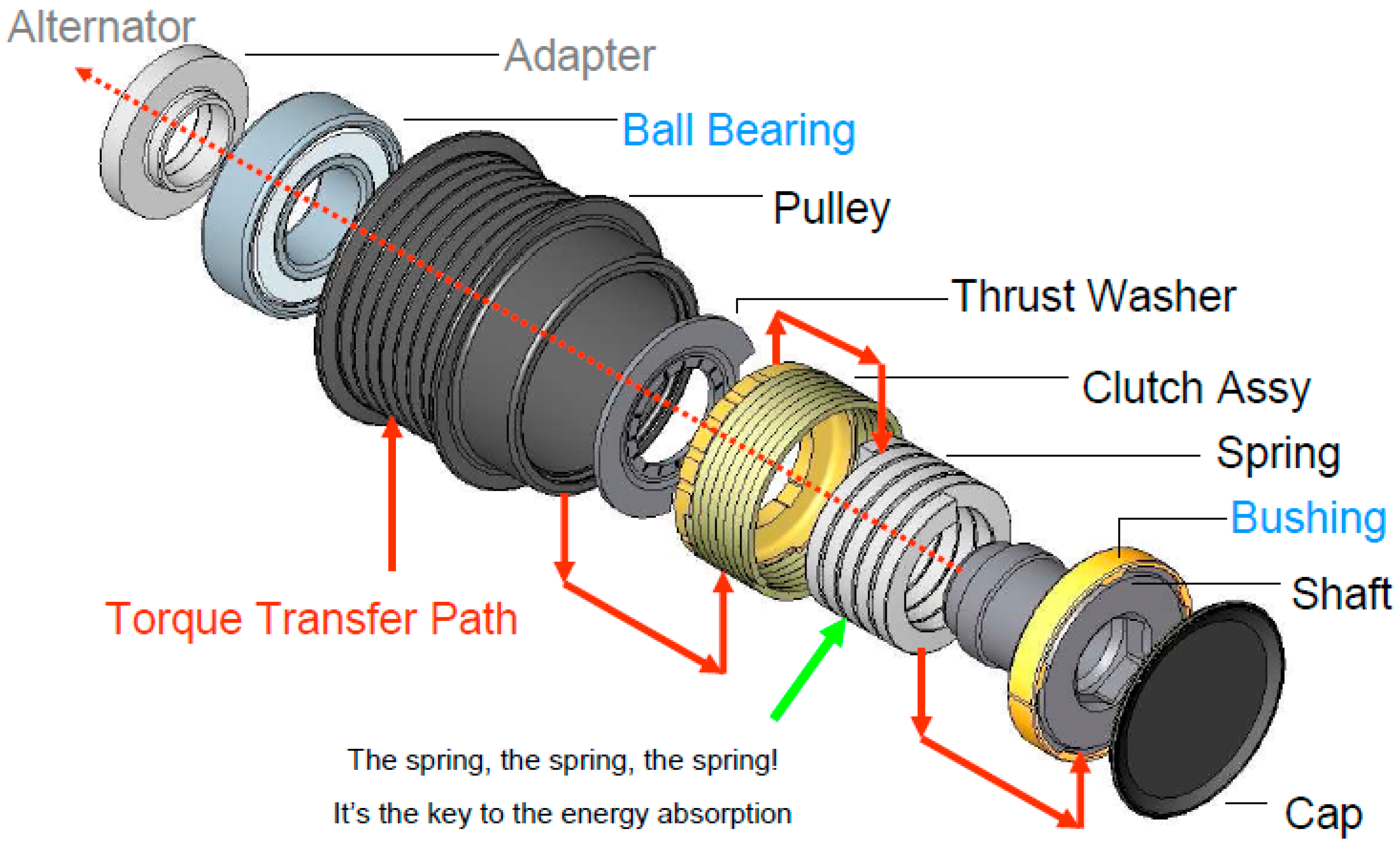
To avoid the impact generated during system engagements, the wrap spring one-way clutch, also called over-running alternator de-coupler (OAD), as shown in
Figure 1 was used. It has a torsional wrap spring-damper that connects the pulley to the outer ring of the clutch [
4,
5,
6,
7,
8]. In wrap-spring clutches, a helical spring, typically wound with square-cross-section wire, is used. The torsion spring also acts as a dampening mechanism which greatly reduces the belt vibration.
The application of the one-way clutch has a strong influence on the entire system’s dynamic behavior. Under certain circumstances, the unique features of the one-way clutch allow the belt spans to experience large transverse vibrations or the clutch to have larger torsional vibrations. There are many research studies dedicated to the vibration analysis of a one-way clutch. To accurately predict the entire system’s dynamic behavior, the motions of the one-way clutch need to be considered in the models. This results in a strong nonlinear system due to the special stiffness discontinuous property of the one-way clutch. Balaji and Mockensturm established a mathematical model of accessory system with seven pulleys with a one-way clutch, and the piece-wise linear system is numerically solved for specific cases using the Runge-Kutta method [
10]. Ding and Zu solved a similar model numerically and used fast Fourier transform to derive the natural frequency of the nonlinear vibration [
11]. For the similar model, Ding and Hu used two different approaches: (a) The nontrivial solutions of viscoelastic model; and (b) the iterative solution, to determine the nontrivial equilibriums of dynamical system numerically. They also studied the natural frequencies of the system by using the Galerkin method [
12]. Zhu and Parker established a model of the accessory system with two pulleys having a one-way clutch, and the dynamical system was analyzed by using the harmonic balance method, with the dynamical properties characterized in terms of spring stiffness, excitation amplitude, and moment inertia of pulleys [
13]. Zeng and Shangguan established a model of the accessory system, with three pulleys having a one-way clutch, which consists of a driving pulley, a driven pulley and a tensioner. The dynamical system is analyzed numerically by using the Gear method, with the dynamical properties being characterized and optimized in terms of clutch spring stiffness, excitation amplitude and moment inertia of pulleys [
14]. In-vehicle experimental tests are a significant way to investigate the vibrations of alternator pulleys. An experimental procedure, including proper selection of parameters, measures and sensors, to evaluate the potential vibrations of each alternator pulley is proposed by Michelotti, Pastorelli et al. [
15]. The existing research characterizes many linear and nonlinear vibration properties of one-way clutch for many specific cases. There has been a lack of overall understanding of global characteristics of the strong nonlinear vibrations of one-way clutch system. For practicing accessory drive designers in the automotive/heavy vehicle industries, the natural frequencies and dynamic response are of utmost interest. Predicting the system’s dynamic behavior in the design stage is important because the changes are difficult to accomplish once prototypes are built. This requires a comprehensive model of the one-way clutch to characterize the system’s properties, particularly all kinds of resonances. In this paper, the functional principles of the one-way clutch will be theoretically investigated and explained while the comprehensive resonances features will be reported. The analytical results clearly show that there exist primary, subharmonic, and superharmonic resonances. The numerical analysis illustrated the detailed cases. This study offers some insights for the product design into how to pinpoint and avoid varied resonance cases.
2. Mathematical Model
Based on the real system of the wrap-spring one-way clutch [
4,
5,
6,
7,
8,
9,
10,
11,
12,
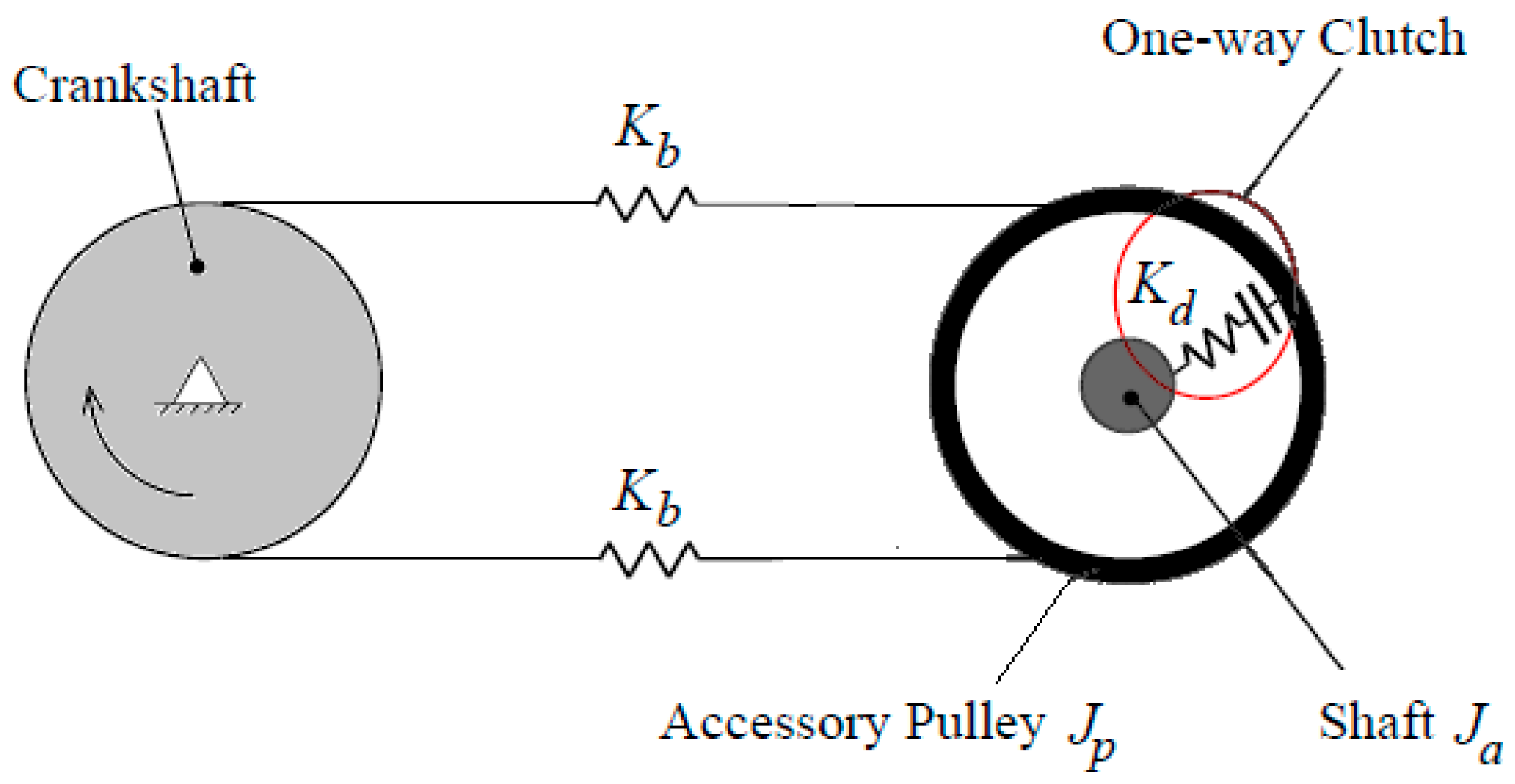
13], the model is given as follows. When the rotations of the wrap-spring ends, for which the pulley rotation exceeds the accessory shaft rotation, then the clutch is engaged. Power transmission takes place from the driving to the driven pulley. For the alternate case where accessory rotation is less than pulley rotation, the wrap-spring diameter decreases and the clutch disengages; no torque is transmitted. A theoretical model of one-way clutch on a two-pulley system is shown in
Figure 2. The driving pulley represents the crankshaft, and its motion is specified as harmonic oscillation. In vehicle applications, engine firing pulsations induce periodic fluctuations in crankshaft speed at the firing frequency. The driven pulley was connected to the accessory. The one-way clutch is integrated between the accessory pulley and the alternator shaft. The mathematical model of the system is given by the following equations:
in which:
and
are the vibration angle of driven pulley and alternator shaft, respectively;
and
are the moment of inertia of driven pulley and alternator shaft, respectively;
and
are the damping and stiffness constants associated with driven pulley, respectively;
, and
and
are the damping and stiffness constants associated with the rotor of alternator, respectively.
and
are respectively the amplitude and frequency of excitation acted on driven pulley due to engine firing excitation. The torque transmitted between the accessory pulley and alternator shaft is given as follows,
The equation described by Equation (1) has been studied numerically and theoretically under particular conditions [
13].
Generally, Equation (1) represents a strong nonlinear system. Consider the simplest case,
; the system is linear and the squares of the natural frequencies are derived as
in which
,
and
. Furthermore, letting
, which deteriorates to the natural frequencies of two independent systems: The accessory system and the uncoupled alternator. For the case with both
and
, the system exhibits a nonlinear feature.
Consider the case in which the driven pulley mode and alternator shaft mode motion can be decoupled, and we just discuss driven pulley mode, then Equation (1) can be approximated by
By using the approach given in References [
16,
17], a comprehensive analytical solution is systematically derived through the discontinuous transformation, and the results are given in next section.
4. Numerical Analysis
In this section, the numerical analysis of a typical one-way clutch system, characterized by Equation (1), is presented.
Table 1 shows the parameters for the typical system. The frequency,
, is considered as the natural frequency for the linear single degree of freedom system when the accessory is not equipped with one-way clutch, and
. Corresponding to the case of the linear system which is mentioned in
Section 2, the dimensionless natural frequencies are
and
for the values in
Table 1. These two dimensionless natural frequencies could be the criterion to evaluate how the system works under different conditions.
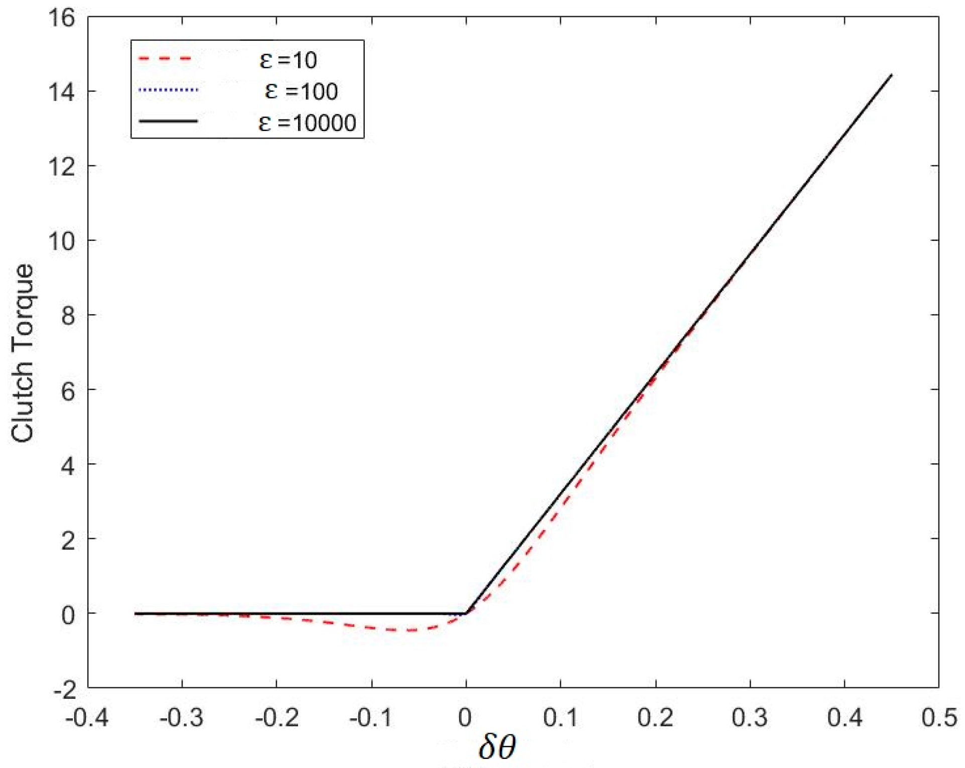
To conduct the numerical analysis of the dynamic model with the above parameters using MATLAB, the discontinuous stiffness nonlinearity which was indicated by Equation (2) can be efficiently approximated as a continuous function. A smoothed function is used to approximate the discontinuous stiffness nonlinearity
.
in which
, and the
is the smooth constant which is usually a large positive number, for instance,
[
13]. The clutch torque is approximated by a hyperbolic tangent function as shown in
Figure 4. What we want the approximated function to be is a proportional function, with the slope being
when
and being 0 when
. As shown by the results in
Figure 4, the approximation is obviously not accurate when
because the curve deviates from the desired trajectory, and the satisfied approximation is likely to be obtained for large
. This is because the results of
and
look to have overlapped each other in the figure. The actual effects of different values of
will be further investigated when conducting the frequency analysis by employing these values below.
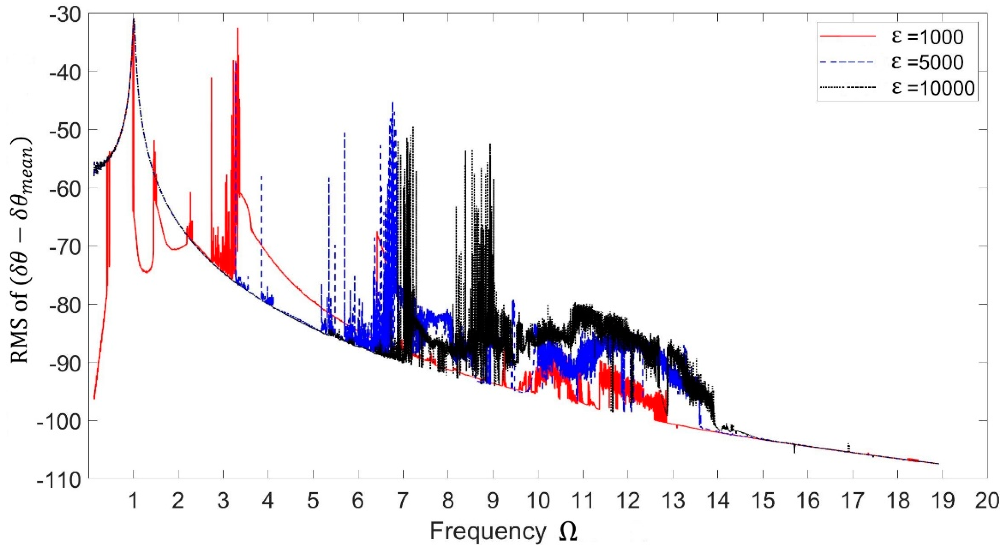
From numerical investigation, we can estimate the effects of the approximations with a different smooth constant,
, for frequency analysis of the system as shown in
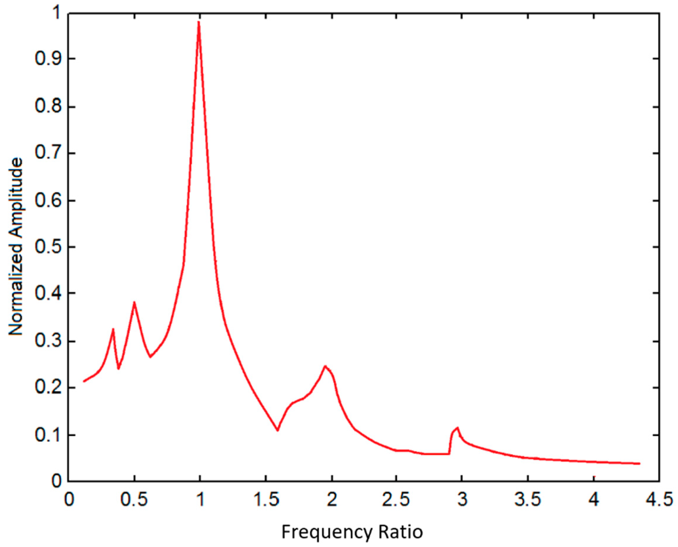
Figure 5. In this case,
is the ratio of excitation frequency and natural frequency of the system.
From investigation we found that the approximation is compromised in numerical analysis with because the trajectory is not only discontinuous and disorderly, but also violate the natural frequencies we derived above. An acceptable approximation is attained by using . The approximation is well accomplished by using , the curve is continuous, and we can clearly see the peaks of resonance around and . Thus, a value is employed when conducting the following numerical analysis.
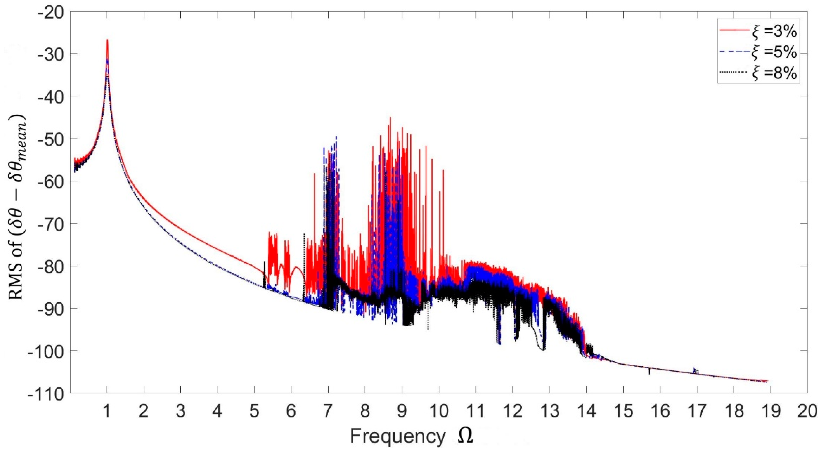
In the engine front-end accessory system, the excitation frequency is the engine firing frequency which changes in a wide range. The root mean square (r.m.s.) of dynamic amplitude of the relative pulley-accessory rotation,
, versus excitation frequency, for different values of damping ratios (
are calculated and the results are shown in
Figure 6 for the parameters listed in
Table 1.
The frequency response for shows that the behavior can be considered as linear. For , non-linear phenomena appear. It indicates that the system is sensitive to the excitation amplitude. As we can see, there are two resonant regions within the two natural frequencies. The system is linear when the clutch is engaged. The non-linearity occurs near the second resonant region due to the decoupling of the clutch where the spring between pulley and accessory shaft is inactive. The pulley and accessory shaft rotate in opposite directions near the second resonant region. This behavior is called out-of-phase motion, and it tends to clutch disengagement. The amplitude is higher near the first resonant region because of the in-phase motion of pulley and accessory shaft. This means that the pulley and accessory shaft move in the same direction and are excited more directly by the excitation from crankshaft vibration.
In this section, we employ a hyperbolic tangent function to approximate the discontinuous nonlinearity of the system when conducting numerical analysis. Actual effects of different parameters, smooth constant and damping ratio , on the numerical analysis of the mathematical model are investigated.
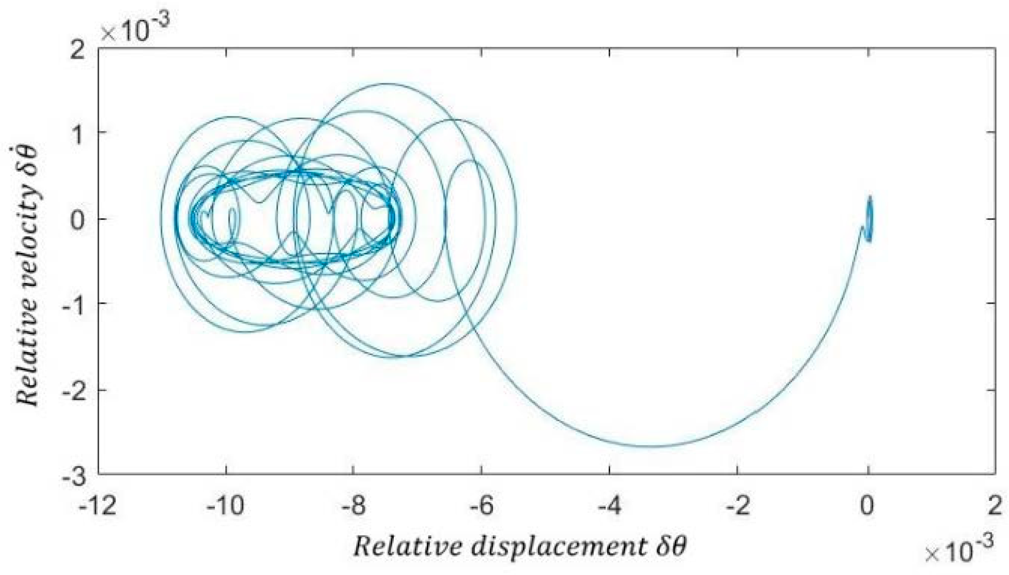
The phase plot and time response are shown in
Figure 7 and
Figure 8, respectively, by employing a sample excitation frequency of
. The relative displacement
, which is
, was considered as an important value to investigate the response of the dynamic system.
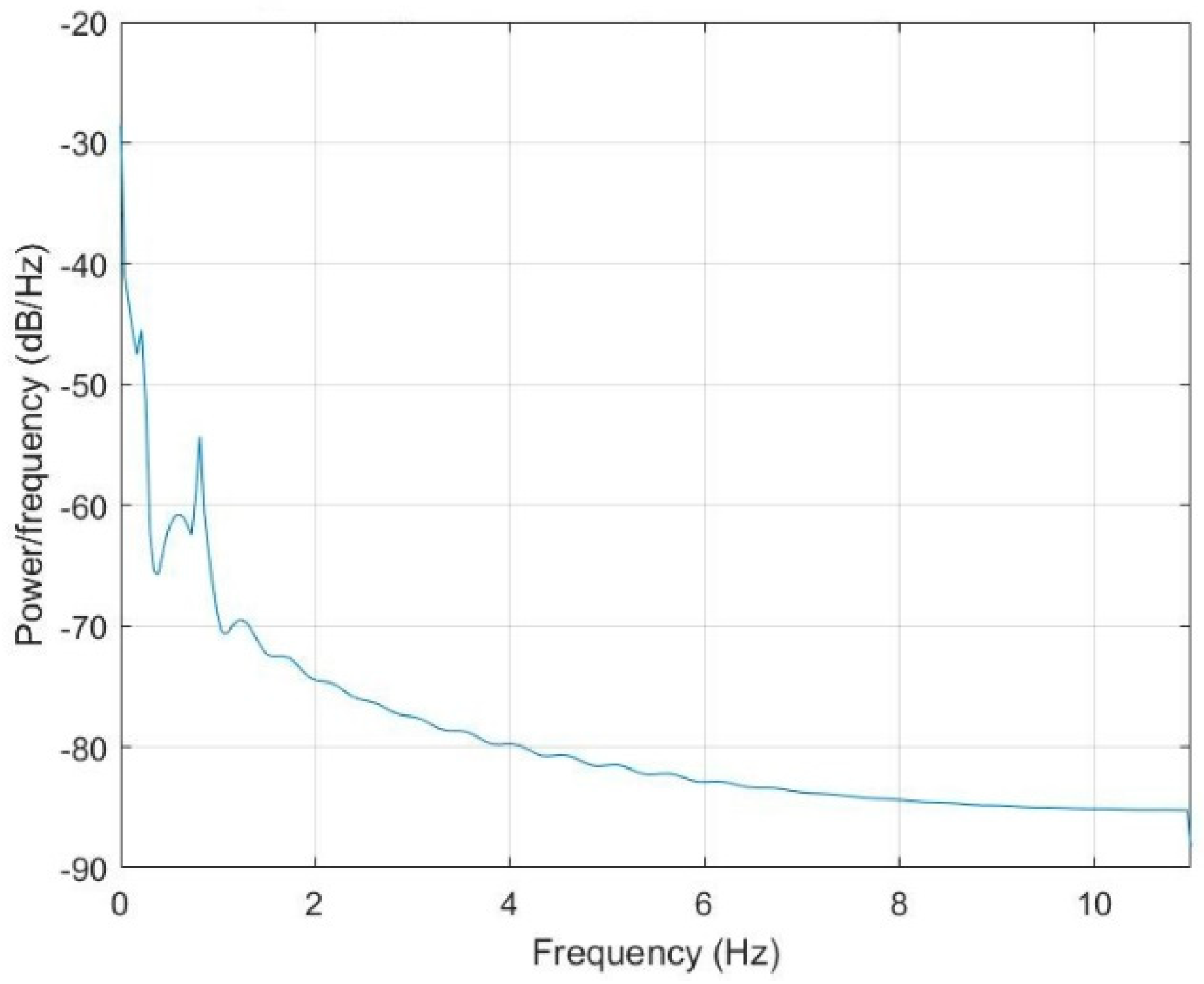
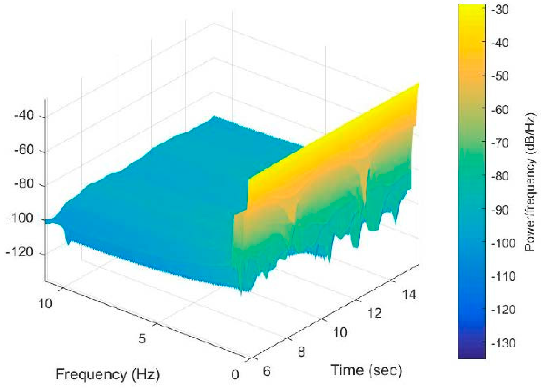
The corresponding periodogram power spectral density estimate of
and waterfall plot of the spectra of
are shown in
Figure 9 and
Figure 10.


