Inventions and Innovations in Preclinical Platforms for Cancer Research


1
Department of Mechanical Engineering, Sharif University of Technology, Tehran 11155-9567, Iran
2
School of Biomedical Engineering and Institute for Biomedical Materials & Devices (IBMD), University of Technology Sydney, Ultimo NSW 2007, Australia
*
Authors to whom correspondence should be addressed.
Inventions 2018, 3(3), 43; https://doi.org/10.3390/inventions3030043
Submission received: 29 May 2018
/
Revised: 24 June 2018
/
Accepted: 27 June 2018
/
Published: 3 July 2018
(This article belongs to the Section Inventions and Innovation in Biotechnology and Materials)
Abstract
:Three-dimensional (3D) cell culture systems can be regarded as suitable platforms to bridge the huge gap between animal studies and two-dimensional (2D) monolayer cell culture to study chronic diseases such as cancer. In particular, the preclinical platforms for multicellular spheroid formation and culture can be regarded as ideal in vitro tumour models. The complex tumour microenvironment such as hypoxic region and necrotic core can be recapitulated in 3D spheroid configuration. Cells aggregated in spheroid structures can better illustrate the performance of anti-cancer drugs as well. Various methods have been proposed so far to create such 3D spheroid aggregations. Both conventional techniques and microfluidic methods can be used for generation of multicellular spheroids. In this review paper, we first discuss various spheroid formation phases. Then, the conventional spheroid formation techniques such as bioreactor flasks, liquid overlay and hanging droplet technique are explained. Next, a particular topic of the hydrogel in spheroid formation and culture is explored. This topic has received less attention in the literature. Hydrogels entail some advantages to the spheroid formation and culture such as size uniformity, the formation of porous spheroids or hetero-spheroids as well as chemosensitivity and invasion assays and protecting from shear stress. Finally, microfluidic methods for spheroid formation and culture are briefly reviewed.
1. Introduction
A vast number of investigations are being conducted in laboratories and research centres to produce drugs to cure cancer but few of them can lead to the production of practical and useful drugs. The main reason of that most probably relates to the procedures utilized for experiments and to the in vitro platforms for drug screening. As a proof, cancer drug assays in mice, pig and monkeys can be mentioned, which are predominantly being performed in many laboratories [1]. In fact, these tests can be beneficial for a general understanding of what happens during the whole process in a systemic environment but may not be suitable for the drugs that are being generated for human that have different genotype and phenotype of such animals. Those few drugs that show the effectiveness of cancer treatment in animal bodies, are used for human clinical trials. Such clinical trials need complicated protocols and require a large number of cancer patients to take part in the experiment. In the majority of these experiments, the drug fails to perform the expected task efficiently. Accordingly, the whole process and investment get wasted and can lead to a significant loss of materials, equipment, time and money.
Parallel to what we call animal tests, other types of tests for drug investigation also exist which are performed using different kinds of methods and equipment. In these methods, cancer cell lines of human or laboratory animals are used. Although in such platforms the cells belong to human, the deficiency is the lack of physical and chemical parameters that exist in the tumour microenvironment. For instance, in an in vivo tumour microenvironment, there is continuous perfusion of oxygen and nutrients, as well as removal of cellular waste products. However, these features are absent in most in vitro cancer drug screening platforms such as microwell plates or Petri dishes [2]. This continuous perfusion and diffusion cause chemical gradients to be made in vivo at tumour sites like hypoxic core which is essential for realistic in vitro assays.
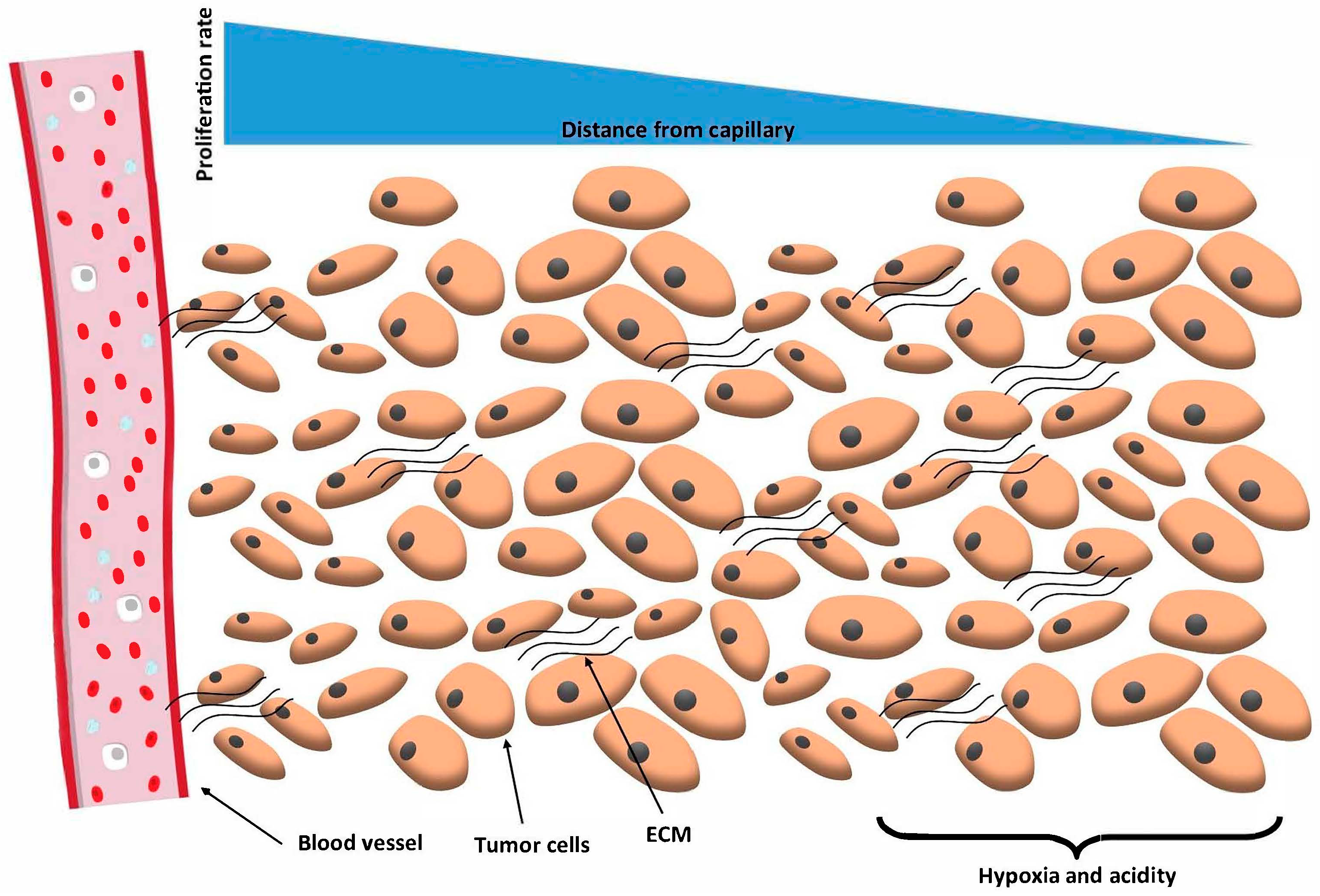
Tumour microenvironment has several distinctive features [3], Figure 1. First, tumour microenvironment is hypoxic. Hypoxia occurs as the tumour grows because no capillary has been generated in tumour yet [4]. The second feature is angiogenesis in which blood vessels are generated through cancer tumour to deliver oxygen and nutrients to the cells which are proliferating in the tumour [5]. This phenomenon develops oxygen gradients in the tumour to generate hypoxic and necrotic regions in it. As the third trait, tumours are composed of different kinds of cells, including tumour cells, cancer stem cells, fibroblasts, white blood cells (e.g., lymphocytes, macrophages and neutrophils), fat cells (adipocytes), pericytes and endothelial cells (induced by angiogenesis). So, it is evident that for a realistic tumour microenvironment, we need to make tumour cultures that are composed of different types of cells (cell co-culture) as mentioned above. This issue is easy to handle via microfluidic cell culture chips fabricated by many groups all around the world in the last decade. Another feature of tumour cancer cells is their tendency of metastasis. Metastasis is a migration of cancer cells from tumour environment to other places in the body using blood circulation or lymphatic nodes. The act of crossing the endothelial barrier and entering blood flow is called intravasation. After entering blood flow, the migratory cancer cell may find a susceptible region to cross the endothelial barrier and hence diffuse to another organ; this action is extravasation [6].
In this paper, we focus mostly on the approaches and the platforms that provide a 3D environment for the cancer cells in mono- and co-cultures. This feature is the most significant feature of the tumour environment which dominantly modifies the outcome of the chemotherapy, photodynamic therapy and so forth on the cancer cells [7,8,9]. There are a few microfluidic platforms for modelling the angiogenesis, cancer cell migration and metastasis which are not the main purpose of this review [10,11]. The three-dimensionality of the tumour cell culture environment has significant effects on tumour cell responses to cancer drugs due to the cell-cell interactions and the hypoxia condition which take place only in a three-dimensional (3D) configuration of cells. This fact indicates that monolayer, two-dimensional (2D) cell cultures (mostly used cultures) are unable to mimic the in vivo behaviour of cancer cells accurately [12].
The 3D cell culture formation methods have been vastly discussed in the literature but practically, multiwell plates along with bioreactors and hanging droplet plates have been commercialized and used by many scientists to form spheroids. Although these approaches have several advantages, it has been justified that microfluidic devices are capable of forming 3D cell cultures (like spheroids and hydrogel-based cancer cell encapsulation) and drug tests in high throughput, more efficient and better-mimicked microenvironments [13]. For instance, the static microenvironment existing in a well in a microtiter plate causes fast depletion of oxygen and nutrients while increasing waste concentration in the well. This can influence the spheroid formation and the future results of the drug tests that need be performed on the tumour [14]. The similarities between in vivo tumour microenvironment and the tumour spheroids extend further. For instance, the cell proliferation activity in 3D spheroids of malignant pleural mesothelioma is more similar to that in biopsied cells [15]. Several studies illustrated that gene expressions were altered in 2D monolayer cancer cell cultures while results obtained from spheroids captured the in vivo tumour tissue expressions [16] partly as a result of higher production of the cell adhesion molecules such as E-cadherin. Growth kinetics is also a crucial factor in tumour spheroids which resembles in vivo tumours [17].
The spheroid culture of cells is not limited to cancer cells. Cell spheroids have been used as 3D cell cultures for mesenchymal stem cells (MSCs) [18], liver tissue [19], cardiac muscle [20], human embryonic kidney cells [21] and so forth. Embryonic stem cells, neural stem cells, pancreatic cells and hepatocytes also need to be cultured in 3D configurations to induce differentiation and express their own metabolism and proliferation rate similar to the in vivo conditions. Sometimes these cell spheroids are given different names such as neurospheres or embryoid/organoid body according to their cell type [22]. Spheroid formation process with these cells is similar to those made of cancerous cells. These cell spheroids have all the features mentioned above except that some quantities differ among them including spheroid formation time, oxygen uptake and diffusion and hypoxia limit. For instance, oxygen diffusion limitations develop necrotic core in both cancerous and hepatic spheroids when the spheroid grows more than a specified diameter (e.g., 150–200 µm for hepatic cells and 500 µm for cancerous cells [23]).
Here, first various spheroid formation phases will be introduced. After a brief review of the conventional spheroid formation techniques, the pros and cons of these methods will be presented. Next, the effect of hydrogel in spheroid formation and culture will be evaluated. Finally, microfluidic methods for spheroid formation and culture will be briefly studied.
2. Spheroid Formation Phases
In general, we can divide the spheroid formation process into three phases [24]. Forming cellular aggregates and making compact spheroids within the first days is called the first phase. Spheroid diameter decreases during the first phase because cells are attaching to each other and forming stable aggregates [25], Figure 2A. The duration time of the first phase depends on the cell type as well as the method used. For example, Torisawa et al. [26] reported that HepG2 cells took three days to form spheroids, while Michigan Cancer Foundation-7 (MCF-7) cells only took two days on the same microchip. Chan and colleagues [18] also observed different time durations required for HepG2, Mesenchymal Stem Cell (MSC), primary mouse embryo fibroblast (PMEF) and Caco-2 cell lines to form spheroids in a single microfluidic device. Using hanging droplet (HD) method, Kelm et al. [27] claimed four days for HepG2 and five days for MCF-7 which were much longer than 24 h reported by those who used microfluidic spheroid formation chips (µSFCs) from the same cell lines [28]. These data suggest that spheroid formation time depends strongly on the cell type and is attainable to be reduced using dynamic flow µSFCs instead of conventional methods with static flow conditions.
It has been reported that not all cell lines can form spheroids or at least have a lower tendency [29]. Increasing the foetal bovine serum (FBS) [30] or reconstituted basement membrane (rBM) [31] concentration in the culture media can enhance cell aggregation. Hence, it is possible to decrease spheroid formation duration time by elevating the level of FBS or rBM in the culture media. Frey and co-workers [30] investigated the effect of FBS concentration on the spheroid formation. The authors reported that 0% concentration of FBS led to no spheroid formation while the higher concentrations gave rise to larger spheroids.
In the second phase, spheroids face high proliferation rates and biomass production [32]. Human colon carcinoma cells (HT-29) continue to proliferate for seven days from the third day [32]. This phase is reported to be four days (starting from the second day) for human colon carcinoma cells (HCT116) [24] and lasted up to the fifth day for co-culture of hepatocytes and hepatic stellate cells [33] on µSFCs. In the third phase, reported by Ziółkowska et al. [32], the spheroid growth and cellular proliferation slowed down after ten days of culture and spheroid size tended to a constant diameter (Figure 2(B1)). A similar trend was reported by Lee and co-workers [33] where this phase occurred from the fifth day onwards for hepatocyte spheroids in accordance with the decrease in spheroid size. Chen et al. [24] also recorded this phase to begin at the sixth day for human colon carcinoma cells (HCT116).
3. Conventional Methods for Spheroid Formation
There are several methods for cell spheroid formation other than the microfluidic approach including magnetic levitation [34], 3D-bioprinting [35], hydrophobic surfaces [36], matrix-on-top [37], matrix-embedded [38], polymeric aqueous two-phase system [39], floating liquid marbles [40], multiwell plates [41], bioreactor flasks [42], liquid overlay [43] and HD techniques [36]. Some of these techniques such as HD and multiwell plates are laborious while some others like 3D-bioprinting and magnetic levitation are costly and still lack the standard protocols. A key parameter for cell spheroid formation is the required time. The bioreactor flasks and the liquid overlay method are very time-consuming in comparison with others. The other methods such as those utilizing a hydrogel matrix and the polymeric aqueous two-phase system are not so common because the required materials are costly or out of access.
The most important thing is the culture microenvironment of the cell spheroid, not only the method used for spheroid generation. A question arises here: Are the cell spheroids generated by these methods cultured in an in vivo-like microenvironment? Maybe it would be easier to form a cell spheroid and culture it in the same platform afterward. A platform which gives the necessary conditions for mimicking the in vivo microenvironment for cells would be desired. To find the answer to the question, we go through the following section in which we describe conventional methods routinely used for spheroid formation beside discussing their advantages and drawbacks in comparison with microfluidic techniques. Among the various non-microfluidic methods, the bioreactor flasks, liquid overlay method and the HD method are chosen to be discussed because of their conventionality, ease of use and existence of standard protocols.
3.1. Bioreactor Flasks
One of the most high-throughput approaches for spheroid formation and culture is the use of bioreactors. In this approach, cells are suspended in culture media while being circulated due to the spinner motion [44] or wall motion [17]. The dynamic environment in the bioreactors is designed to prevent cell sedimentation and also enhance the stirring of the media and oxygen transfer; meanwhile, cells are exposed to nutrients in the absence of large concentration gradients. However, these devices are not suitable for drug screening since they require a high content of drug and culture media and also cannot mimic the in vivo microenvironment [45]. Thus, for this purpose spheroids must be retrieved and put into other culture platforms such as the multiwell plates [42] or microfluidic spheroid culture chips (µSCCs).
In the bioreactor, cell aggregates of various diameters are formed after a given time, depending on the type of the cell line and the bioreactor physical features such as speed of stirring [42]. Spheroids may be formed first by other methods and then placed into a bioreactor for culturing [45]. Santo et al. [42] recently developed an adaptable stirred-tank bioreactor culture strategy to perform high throughput spheroid formation (HTSF). Agitation frequency or spinner velocity, as well as cell density, are significant variables in this method of spheroid formation. As reported by Santo et al. [42] and Nyberg et al. [46] as agitation frequency increased, smaller spheroids were generated. However, the agitation or stirring rate must be kept above a specific value to hinder cell sedimentation during the spheroid formation process. Since it is common to culture cell spheroids for long times (e.g., 2 weeks) in bioreactor flasks, it is crucial to ensure that the shear stress acting on cells in the bioreactor is not high to affect the study results. Therefore, the spinner design and the circulating frequency should be adjusted in such a way that the cells have a solid body motion to minimize the shear stress [47].
3.2. Liquid Overlay Method
In this method, a cell suspension is dispensed in a dish or a multiwell plate with non-adherent bottom surface. This surface is frequently coated with agar or agarose to prevent cell-substrate attachment [43,48]. Friedrich et al. developed a promising protocol for spheroid-based high throughput drug screening in which they coated the bottom surface of the wells of multiwell plates with agarose [48]. PEG (polyethylene glycol) [49] and polystyrene plastic [50] materials are also used as a non-adherent surface for spheroid formation.
Human cells take one to two days to aggregate. However, not all the cells can generate cell-cell bindings, meaning that a large number of individual cells exists in addition to the cell aggregates. Thus, the excess cells should be extracted from the dish by sedimentation separation or other techniques. A large number of the aggregated cell clusters are not spheroids since some of them have irregular shapes. After spheroid formation, they are pipetted out from the dish and placed in microwell plates or bioreactors for long-term culture and drug efficacy tests because the primitive dishes are not suitable for these purposes [43].
3.3. Hanging Droplet (HD) Method
One of the best conventional methods for spheroid formation is the HD technique, Figure 3A,B. In these platforms, highly regular spheroids can be generated in microliter droplets in a short period of time [27]. Kelm et al. [27] reported that the coefficient of variation (CV) of the spheroid diameter of HepG2 spheroids made by this method was 10 to 15%, even 5% for MCF-7 spheroids. Comparing these results with the corresponding values of 40 to 60% for spheroid formation on non-adherent surfaces in the liquid overlay method signifies the capability of this method in uniform size spheroid formation. The uniformity and compactness of spheroids made by those cells that exhibit a low tendency of aggregation such as pancreatic cancer cells, can be improved using methylcellulose in HDs [51].
Tung et al. [52] designed a novel HD platform to ease the procedure being traditionally used for HD spheroid formation [53]. The platform was compatible with liquid handling robots as well as conventional plate readers available for 384 & 96-well plates to facilitate high throughput drug screening. Although these advancements were crucial in spheroid formation, the inherent characteristics such as static environment, transient oxygen and nutrient concentrations and osmolality changes due to evaporation confine its ability to mimic the in vivo microenvironments. Liquid evaporation within the wells and droplets leads to an increase in osmolality that can negatively affect cell viability [52]. Specific amounts of culture media should be exchanged manually with the delicate droplets every day to compensate for the evaporated liquid.
Recently, the deficiency of lacking a dynamic microenvironment in HD platforms has been solved by novel microfluidic designs [54]. In a valuable work by Yazdi et al. [54], both pulsatile and steady-state flows were promoted through the device by pneumatic actuation to mimic the in vivo microenvironment for culturing human cardiac induced pluripotent stem- (iPS)-derived spheroids. These platforms enabled closed-looped circulation of medium. However, the platform still needed adding fresh culture medium to compensate the evaporated liquid [30].
4. Hydrogels in Spheroid Culture
In contrast to 2D monolayer as well as 3D hydrogel based cultures, the existence of the natural extracellular matrix (ECM) between the cells in a spheroid decreases the permeability and the diffusion rate of drugs and other species of the culture media. As the cell secretions construct the natural ECM between cells inside a tissue [55], no synthetic or exogenous hydrogels are required to form tumour spheroids. This effectively reduces the equipment and efforts to have a suitable 3D tumour microenvironment in contrast to hydrogel-based 3D cultures. The hydrogel-based methods require gelification, additional materials, for example, CaCl2 (in case of alginate) [56] and equipment such as hydrogel handling dishes and heating facilities to adjust temperature for crosslinking. However, using hydrogels entails some advantages to the spheroid formation and culture such as size uniformity [57], the formation of porous spheroids [58] or hetero-spheroids [59]. Hydrogels can also facilitate chemosensitivity [60] and invasion assays [61] and can protecting the spheroids from shear stress [18].
Porous spheroids were formed with the goal of increasing nutrient and oxygen exchange [26] between cells and culture medium by Kojima et al. [19]. To have porous spheroids from hepatoma cell line (HepG2), 20 µm diameter alginate droplets were generated and added to the cell suspension. After creating the spheroids using the cell-droplet mixture, the spheroids were made porous by alginate lyse treatment to remove the alginate from the structure of the spheroids. It was shown that 1 µm polystyrene particles could enter the central parts while this diffusion was confined only to the few outer layers of conventional (non-porous) spheroids. Yamada and colleagues [58] generated spheroids with various mixtures of HepG2 cells and 10 µm collagen microdroplets in 1024 agarose microwells. They observed that the ratio between the collagen microdroplets and cells influences the hepatic function characteristics noticeably.
Ota et al. [59] used collagen hydrogels for strengthening the bonding between hepatocyte and endothelial cells in the spheroids by a coating of 200 nm collagen gel on cells. Collagen gel was also used for covering hepatocyte spheroids with endothelial cells by coating the hepatocyte spheroids initially with the collagen gel [62]. As cell-cell adhesions and attachments between non-identical cells develop slower and weaker [59], collagen gel acts as an anchorage for endothelial cells to stick to the hepatocyte spheroid preference. In an interesting work, Sabhachandani et al. [63] used alginate as a hydrogel to encapsulate breast cancer cells (MCF-7) and fibroblast cells to form co-cultured spheroids in a microfluidic device. Alginate hydrogel permits facile de-crosslinking with the aid of calcium chelator, therefore, the spheroids can be retrieved for subsequent culture and assays [64].
Placing tumour spheroids in a hydrogel and then crosslinking the gel hinders the dissociation of the spheroids [18], since the hydrogel plays the role of the in vivo surrounding tissue. However, it can damage cells on outer layers of spheroid due to the shear stress of the hydrogel itself [18]. Furthermore, hydrogel protects cells from the shear stress caused by the culture medium flow [65]. Sometimes, cells are dispensed in hydrogel droplets and anchored in a chip for spheroid formation and assays [66].
5. Microfluidic Methods for Spheroid Culture
Microfluidics is the science and technology of handling a small volume of fluids in the channels with sub-millimetre length scale [67,68]. As a science and technology, microfluidics can be used for various fluid mechanics applications, including slip flow in superhydrophobic microchannels [69,70] and drag reduction [71,72,73]. In parallel, microfluidic systems hold great promise for cell biology [74], assisted reproductive technology (ART) [75], drug delivery systems [76], anti-cancer drug screening [77] and disease modelling [78]. Recently, microfluidic platforms for spheroid formation and culture have been thoroughly reviewed by our group [13]. We categorized the µSFCs into two main groups, which differ in spheroid formation procedure: emulsion-based spheroid formation and; microwell or U-shaped microstructure-based spheroid formation [13].
Many studies have used flow-focusing droplet generators due to the resultant droplet and spheroid size uniformity, in addition to their high-throughput continuous operation [79]. Single- [63,80,81], double- [18,82] and triple- [79] emulsion droplet generation techniques have been used in µSFCs. Axisymmetric [82] or non-axisymmetric [63,79,83] configuration flow-focusing devices exist. This method facilitates the fast production of microdroplets and thus high-throughput spheroid formation (HTSF).
Cell-dispensed hydrogel (Gel) in oil (i.e., Gel/O) and cell suspension (CS) in oil (O) (i.e., CS/O) [84] droplet generation [63,85] are among the single-emulsion methods which are widely used. Cell suspension in oil in culture medium (CM) (i.e., CS/O/CM) [18] and CS/Gel/CM [82] are double-emulsion techniques. Droplet uniformity can be enhanced with CS/Gel/CM double-emulsion technique which entraps the cells firmly within the droplet. It is facilitated by encapsulating the cell-containing core droplet within an alginate hydrogel shell [82,86] that acts as an impermeable barrier with respect to the cells.
Microwells [8,25,87,88,89] and U-shaped microstructures [21,64,90,91,92,93] have been designed for spheroid formation and culture in microfluidic platforms. These structures facilitate short-term [23,94], controllable and uniform diameter [22,95] and compact spheroid generation [32,92]. U-shaped microstructures either are actuated temporarily using pneumatics [91,92,93,96] or are fixed within the device [90,93]. A large number of these U-shaped microstructures were embedded (e.g., 360 [92], 28 [64], 512 [97]) in each microchamber of the µSFC to trap the cells [64,90,92,93,96] or the cell dispensed hydrogel droplets [64] introduced into the chip. Spheroid diameter is confined to the microstructure size and the relative position of the microstructures is essential for efficient cell trapping. We have recently evaluated the oxygen and glucose distributions inside spheroids in such bioreactor [98] and compare the results with those inside toroidal multicellular aggregates [99].
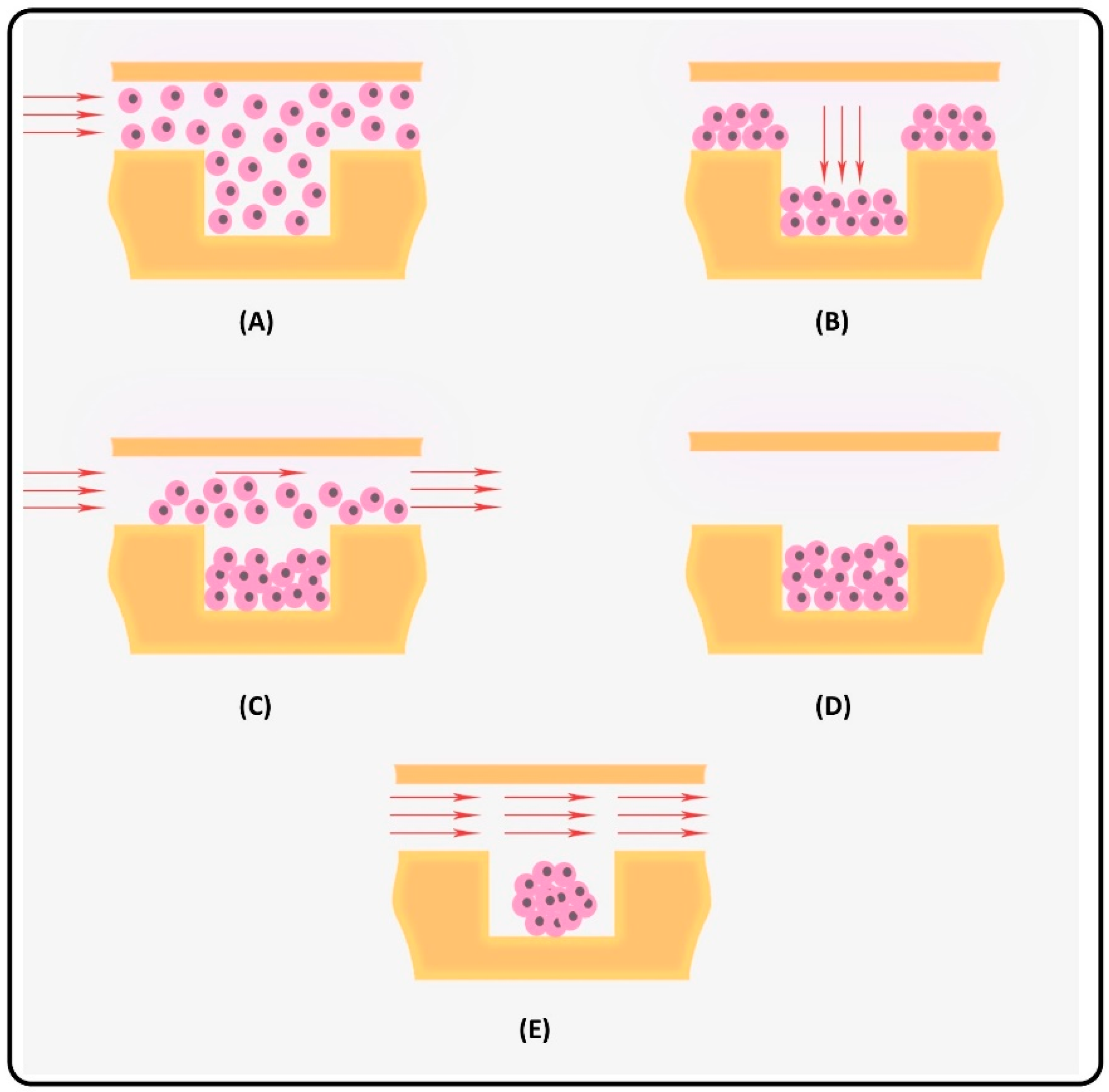
Microwells have been widely utilized in µSFCs due to their simplicity and ease of operation [100,101,102]. Uniform cell seeding in microwells and uniformly sized spheroids are achieved by filling the device entirely with the cell suspension before cells begin to enter and trap in the microwells (Figure 4A). Few minutes are needed that cells deposit on the bottom of the microwells and the microchannel (Figure 4B). The cells that did not trap in the microwells are pushed out of the chip before the cells make aggregations and clog microchannels [8,24,103] (Figure 4C). Next, the cells begin aggregation and form spheroids (Figure 4D) and are culture for drug screening (Figure 4E).
Other works have used acoustic tweezers [104], pyramid microwells [26], porous membranes [105] and microrotational flow [23] in µSFCs for more efficient spheroid formation. We have recently shown that electrospinning technique can be efficiently used to fabricate porous membrane [106] and incorporation of such membrane inside a microchip can give rise to the formation of three different cellular aggregates, namely, single cells, monolayer and spheroid-like tissue [107].
Spheroids retrieval is required for flow cytometry analysis, stem cell differentiation-assays and so forth, however, these flow rates might create high shear stress on the spheroids while pushing them upward [108]. For the real-time on-chip monitoring of the spheroids, several techniques have been developed including the electrode-based biosensors for oxygen [109], glucose and lactate concentration [110] and also pH and electrical impedance [111] measurements. These monitoring techniques alleviate the need for spheroid retrieval from the chip, which effectively reduces the time and cost.
In designing the µSFCs, the concentration of oxygen and glucose in the culture medium and the cellular uptake rates should be considered. The complicated geometries of the µSFCs and the limited diffusion of glucose and oxygen to spheroids create unpredictable concentration profiles within the cultured spheroids. Thus, mathematical and numerical analyses combined with experimental investigations are needed to predict the condition of hypoxia in the spheroids [108,112,113,114,115,116].
The microstructure- or microwell-based µSFCs have limited applications in high-throughput screening. Various drug concentrations and combinations into a µSFC have rarely been carried out simultaneously because a suitable microchannel network did not exist. By coupling the µSFC with a concentration gradient generator chip and arranging the microwells in a configuration compatible with commercial microplate readers, we can become a step closer to the automated monitoring and high-throughput screening within µSFCs.
The µSCC are designed for spheroid culture and their spheroid comes from an external source. They have been designed with various purposes including shear stress analysis [117], drug screening [118], multi organ-on-a-chip [119] and analysis of the spheroid fusion process [120]. Digital microfluidic platforms also are used for spheroid formation and culture [121]. In these devices, the cell suspension of droplets is directed towards hydrophilic of hanging droplet sites for culturing [122,123]. In this method, continuous flow of the culture medium is limited and sequencing delivery of the nutrients is performed [124]. In addition, biofouling and liquid evaporation are the drawbacks of these platforms [125]. The detailed design considerations of µSFCs and µSCCs, such as microstructure design, shear stress, spheroid diameter and retrieval mechanism, have been recently reviewed [13].
In Table 1, a large number of microfluidic chips are mentioned which were designed for spheroid formation and culture using various methods. Some critical parameters are reported in the table such as the cell type, spheroid diameter, spheroid formation time, the flow rate though the microchannels and so forth which can be very helpful in designing µSFCs and µSCCs.
6. Discussion
The conventional methods for spheroid formation have some limitations and disadvantages. The microfluidic methods have shown the capability in overcoming some of these problems such as spheroid formation time, size uniformity and shear stress.
The required time in HD plates for spheroid formation is far less than that in spinner flasks. For instance, Kelm et al. [27] reported 4 days to form HepG2 spheroids while it took 4 to 6 weeks in spinner flask bioreactors [133]. However, microfluidic platforms appear to facilitate spheroid formation within a shorter duration of time. Kim et al. [128] showed that spheroid formation took longer in HDs of MCF-7 breast cancer cells than those in the µSFC. Their results demonstrated that at the second day of culture, several cell aggregates existed in each HDs while compact spheroids could be observed in the microwell traps of the µSFC.
As reported by Santo et al. [42], although the spheroids were formed at most on the fourth day in their stirred-tank bioreactor, large size dispersion existed and appeared to be an inherent feature of this method.
Ziółkowska et al. observed that the shear stress on cells was higher in a Petri dish when pipetting the culture media in comparison with the microfluidic culture chip [32]. Kuo et al. reported a size standard deviation of 104% for on dish liquid overlay and 13% for on-chip spheroid diameters [129]. This illustrated that the spheroid size was much more uniform in the microfluidic approach in comparison with that in the liquid overlay technique.
7. Conclusions
The complicated spatio-temporal heterogeneity of cancer necessitates novel preclinical models to be developed for cancer diagnosis and treatment. Among various in vitro models, spheroid formation and culture has received significant attention due to its tumour-like behaviour. In this review, we generally categorized the spheroid formation techniques based on two broad groups: conventional systems and microfluidic platforms. First, we overviewed and compared three different phases of spheroid formation. The duration of each phase depends largely on the cell type, initial cell concentration, surface treatment and the employed method. It was found that the duration of each phase would be shorten in microfluidic systems. Next, we evaluated the non-microfluidic approaches and discussed the details of three most common conventional techniques, viz., bioreactor flasks, liquid overlay and hanging droplet. Finally, more novel approaches such as hydrogel-assisted, emulsion-based and geometrical-based (microwell and U-shape) were briefly discussed.
The three-dimensionality of the tumour cell culture environment has significant effects on tumour cell responses to cancer drugs due to cell-cell and cell-matrix interactions occurring only in a 3D configuration of cells. The 3D cell culture formation methods have been vastly discussed in the literature. However, among these methods multiwell plates, bioreactors and hanging droplet plates have been commercialized for spheroid formation. Such conventional methods such as hanging droplets, liquid overlay and non-adherent surfaces and spinner flask methods for tumour spheroid formation lack the ability to precisely control the number of cells in each spheroid. Therefore, it leads to spheroids with various diameters. This is cumbersome to separate and group the spheroids. Moreover, undesired necrotic cores and acidic environments develop. In addition, drug tests are not usually conclusive on the cells cultured on such platforms. Using these conventional methods also take a lot of time for spheroid formation and is difficult to achieve cell-cell interactions because cells are not situated close enough to each other to obtain rapid cell aggregates and spheroids. Furthermore, the shear stress presenting in roller bottles, suspension culture and pipetting as well as chemical materials, particularly coating materials (polyethylene glycol (PEG), agarose, agar, etc.), might cause irreversible defects on cells which usually cannot be quelled. On the other hand, microfluidic devices can form uniform 3D cell cultures such as spheroids and hydrogel-based cancer cell encapsulation and drug screening can be used more efficiently and in a high throughput manner.
Conflicts of Interest
The authors declare no conflict of interest.
References
- Schachtschneider, K.M.; Schwind, R.M.; Newson, J.; Kinachtchouk, N.; Rizko, M.; Mendoza-Elias, N.; Grippo, P.; Principe, D.R.; Park, A.; Overgaard, N.H.; et al. The Oncopig Cancer Model: An Innovative Large Animal Translational Oncology Platform. Front. Oncol. 2017, 7, 190. [Google Scholar] [CrossRef] [PubMed]
- Goers, L.; Freemont, P.; Polizzi, K.M. Co-culture systems and technologies: Taking synthetic biology to the next level. J. R. Soc. Interface 2014, 11, 20140065. [Google Scholar] [CrossRef] [PubMed]
- Trédan, O.; Galmarini, C.M.; Patel, K.; Tannock, I.F. Drug resistance and the solid tumor microenvironment. J. Natl. Cancer Inst. 2007, 99, 1441–1454. [Google Scholar] [CrossRef] [PubMed]
- Kim, Y.; Lin, Q.; Glazer, P.M.; Yun, Z. Hypoxic tumor microenvironment and cancer cell differentiation. Curr. Mol. Med. 2009, 9, 425–434. [Google Scholar] [CrossRef] [PubMed]
- Muz, B.; de la Puente, P.; Azab, F.; Azab, A.K. The role of hypoxia in cancer progression, angiogenesis, metastasis, and resistance to therapy. Hypoxia 2015, 3, 83–92. [Google Scholar] [CrossRef] [PubMed]
- Chiang, S.P.; Cabrera, R.M.; Segall, J.E. Tumor cell intravasation. Am. J. Physiol. Cell Physiol. 2016, 311, C1–C14. [Google Scholar] [CrossRef] [PubMed]
- Chen, Y.-C.; Lou, X.; Zhang, Z.; Ingram, P.; Yoon, E. High-throughput cancer cell sphere formation for characterizing the efficacy of photo dynamic therapy in 3D cell cultures. Sci. Rep. 2015, 5, 12175. [Google Scholar] [CrossRef] [PubMed]
- Patra, B.; Peng, C.-C.; Liao, W.-H.; Lee, C.-H.; Tung, Y.-C. Drug testing and flow cytometry analysis on a large number of uniform sized tumor spheroids using a microfluidic device. Sci. Rep. 2016, 6, 21061. [Google Scholar] [CrossRef] [PubMed] [Green Version]
- Zuchowska, A.; Jastrzebska, E.; Chudy, M.; Dybko, A.; Brzozka, Z. 3D lung spheroid cultures for evaluation of photodynamic therapy (PDT) procedures in microfluidic Lab-on-a-Chip system. Anal. Chim. Acta 2017, 990, 110–120. [Google Scholar] [CrossRef] [PubMed]
- Kuo, C.-T.; Chiang, C.-L.; Chang, C.-H.; Liu, H.-K.; Huang, G.-S.; Huang, R.Y.-J.; Lee, H.; Huang, C.-S.; Wo, A.M. Modeling of cancer metastasis and drug resistance via biomimetic nano-cilia and microfluidics. Biomaterials 2014, 35, 1562–1571. [Google Scholar] [CrossRef] [PubMed]
- Lee, H.; Park, W.; Ryu, H.; Jeon, N.L. A microfluidic platform for quantitative analysis of cancer angiogenesis and intravasation. Biomicrofluidics 2014, 8, 054102. [Google Scholar] [CrossRef] [PubMed] [Green Version]
- Edmondson, R.; Broglie, J.J.; Adcock, A.F.; Yang, L. Three-dimensional cell culture systems and their applications in drug discovery and cell-based biosensors. Assay Drug Dev. Technol. 2014, 12, 207–218. [Google Scholar] [CrossRef] [PubMed]
- Moshksayan, K.; Kashaninejad, N.; Warkiani, M.E.; Lock, J.G.; Moghadas, H.; Firoozabadi, B.; Saidi, M.S.; Nguyen, N.-T. Spheroids-on-a-chip: Recent advances and design considerations in microfluidic platforms for spheroid formation and culture. Sens. Actuators B Chem. 2018, 263, 151–176. [Google Scholar] [CrossRef]
- Chi, C.-W.; Ahmed, A.H.R.; Dereli-Korkut, Z.; Wang, S. Microfluidic cell chips for high-throughput drug screening. Bioanalysis 2016, 8, 921–937. [Google Scholar] [CrossRef] [PubMed]
- Ruppen, J.; Cortes-Dericks, L.; Marconi, E.; Karoubi, G.; Schmid, R.A.; Peng, R.; Marti, T.M.; Guenat, O.T. A microfluidic platform for chemoresistive testing of multicellular pleural cancer spheroids. Lab Chip 2014, 14, 1198–1205. [Google Scholar] [CrossRef] [PubMed] [Green Version]
- Lin, R.Z.; Chang, H.Y. Recent advances in three-dimensional multicellular spheroid culture for biomedical research. Biotechnol. J. 2008, 3, 1172–1184. [Google Scholar] [CrossRef] [PubMed]
- Ingram, M.; Techy, G.; Saroufeem, R.; Yazan, O.; Narayan, K.; Goodwin, T.; Spaulding, G. Three-dimensional growth patterns of various human tumor cell lines in simulated microgravity of a NASA bioreactor. In Vitro Cell. Dev. Biol. Anim. 1997, 33, 459–466. [Google Scholar] [CrossRef] [PubMed]
- Chan, H.F.; Zhang, Y.; Ho, Y.-P.; Chiu, Y.-L.; Jung, Y.; Leong, K.W. Rapid formation of multicellular spheroids in double-emulsion droplets with controllable microenvironment. Sci. Rep. 2013, 3, 3462. [Google Scholar] [CrossRef] [PubMed]
- Kojima, N.; Takeuchi, S.; Sakai, Y. Fabrication of microchannel network in liver tissue spheroids. In Proceedings of the 16th International Conference on Miniaturized Systems for Chemistry and Life Sciences, MicroTAS, Okinawa, Japan, 28 October–1 November 2012. [Google Scholar]
- Kehat, I.; Kenyagin-Karsenti, D.; Snir, M.; Segev, H.; Amit, M.; Gepstein, A.; Livne, E.; Binah, O.; Itskovitz-Eldor, J.; Gepstein, L. Human embryonic stem cells can differentiate into myocytes with structural and functional properties of cardiomyocytes. J. Clin. Investig. 2001, 108, 407–414. [Google Scholar] [CrossRef] [PubMed] [Green Version]
- Lee, K.; Kim, C.; Yang, J.Y.; Lee, H.; Ahn, B.; Xu, L.; Kang, J.Y.; Oh, K.W. Gravity-oriented microfluidic device for uniform and massive cell spheroid formation. Biomicrofluidics 2012, 6, 014114. [Google Scholar] [CrossRef] [PubMed] [Green Version]
- Fukuda, J.; Nakazawa, K. Hepatocyte spheroid arrays inside microwells connected with microchannels. Biomicrofluidics 2011, 5, 022205. [Google Scholar] [CrossRef] [PubMed] [Green Version]
- Ota, H.; Yamamoto, R.; Deguchi, K.; Tanaka, Y.; Kazoe, Y.; Sato, Y.; Miki, N. Three-dimensional spheroid-forming lab-on-a-chip using micro-rotational flow. Sens. Actuators B Chem. 2010, 147, 359–365. [Google Scholar] [CrossRef]
- Chen, Y.; Gao, D.; Liu, H.; Lin, S.; Jiang, Y. Drug cytotoxicity and signaling pathway analysis with three-dimensional tumor spheroids in a microwell-based microfluidic chip for drug screening. Anal. Chim. Acta 2015, 898, 85–92. [Google Scholar] [CrossRef] [PubMed]
- Ruppen, J.; Wildhaber, F.D.; Strub, C.; Hall, S.R.; Schmid, R.A.; Geiser, T.; Guenat, O.T. Towards personalized medicine: Chemosensitivity assays of patient lung cancer cell spheroids in a perfused microfluidic platform. Lab Chip 2015, 15, 3076–3085. [Google Scholar] [CrossRef] [PubMed] [Green Version]
- Torisawa, Y.-S.; Takagi, A.; Nashimoto, Y.; Yasukawa, T.; Shiku, H.; Matsue, T. A multicellular spheroid array to realize spheroid formation, culture, and viability assay on a chip. Biomaterials 2007, 28, 559–566. [Google Scholar] [CrossRef] [PubMed]
- Kelm, J.M.; Timmins, N.E.; Brown, C.J.; Fussenegger, M.; Nielsen, L.K. Method for generation of homogeneous multicellular tumor spheroids applicable to a wide variety of cell types. Biotechnol. Bioeng. 2003, 83, 173–180. [Google Scholar] [CrossRef] [PubMed]
- Aung, A.; Theprungsirikul, J.; Lim, H.L.; Varghese, S. Chemotaxis-driven assembly of endothelial barrier in a tumor-on-a-chip platform. Lab Chip 2016, 16, 1886–1898. [Google Scholar] [CrossRef] [PubMed] [Green Version]
- Weiswald, L.-B.; Bellet, D.; Dangles-Marie, V. Spherical cancer models in tumor biology. Neoplasia 2015, 17, 1–15. [Google Scholar] [CrossRef] [PubMed]
- Frey, O.; Misun, P.M.; Fluri, D.A.; Hengstler, J.G.; Hierlemann, A. Reconfigurable microfluidic hanging drop network for multi-tissue interaction and analysis. Nat. Commun. 2014, 5, 4250. [Google Scholar] [CrossRef] [PubMed] [Green Version]
- Shen, K.; Lee, J.; Yarmush, M.L.; Parekkadan, B. Microcavity substrates casted from self-assembled microsphere monolayers for spheroid cell culture. Biomed. Microdevices 2014, 16, 609–615. [Google Scholar] [CrossRef] [PubMed] [Green Version]
- Ziółkowska, K.; Stelmachowska, A.; Kwapiszewski, R.; Chudy, M.; Dybko, A.; Brzózka, Z. Long-term three-dimensional cell culture and anticancer drug activity evaluation in a microfluidic chip. Biosens. Bioelectron. 2013, 40, 68–74. [Google Scholar] [CrossRef] [PubMed]
- Lee, S.-A.; Kang, E.; Ju, J.; Kim, D.-S.; Lee, S.-H. Spheroid-based three-dimensional liver-on-a-chip to investigate hepatocyte–hepatic stellate cell interactions and flow effects. Lab Chip 2013, 13, 3529–3537. [Google Scholar] [CrossRef] [PubMed]
- Haisler, W.L.; Timm, D.M.; Gage, J.A.; Tseng, H.; Killian, T.; Souza, G.R. Three-dimensional cell culturing by magnetic levitation. Nat. Protoc. 2013, 8, 1940–1949. [Google Scholar] [CrossRef] [PubMed]
- Faulkner-Jones, A.; Greenhough, S.; King, J.A.; Gardner, J.; Courtney, A.; Shu, W. Development of a valve-based cell printer for the formation of human embryonic stem cell spheroid aggregates. Biofabrication 2013, 5, 015013. [Google Scholar] [CrossRef] [PubMed] [Green Version]
- Neto, A.; Correia, C.; Oliveira, M.; Rial-Hermida, M.; Alvarez-Lorenzo, C.; Reis, R.; Mano, J. A novel hanging spherical drop system for the generation of cellular spheroids and high throughput combinatorial drug screening. Biomater. Sci. 2015, 3, 581–585. [Google Scholar] [CrossRef] [PubMed] [Green Version]
- Allensworth, J.L.; Evans, M.K.; Bertucci, F.; Aldrich, A.J.; Festa, R.A.; Finetti, P.; Ueno, N.T.; Safi, R.; McDonnell, D.P.; Thiele, D.J. Disulfiram (DSF) acts as a copper ionophore to induce copper-dependent oxidative stress and mediate anti-tumor efficacy in inflammatory breast cancer. Mol. Oncol. 2015, 9, 1155–1168. [Google Scholar] [CrossRef] [PubMed] [Green Version]
- Lee, G.Y.; Kenny, P.A.; Lee, E.H.; Bissell, M.J. Three-dimensional culture models of normal and malignant breast epithelial cells. Nat. Methods 2007, 4, 359–365. [Google Scholar] [CrossRef] [PubMed] [Green Version]
- Ham, S.L.; Joshi, R.; Luker, G.D.; Tavana, H. Engineered breast cancer cell spheroids reproduce biologic properties of solid tumors. Adv. Healthc. Mater. 2016, 5, 2788–2798. [Google Scholar] [CrossRef] [PubMed]
- Vadivelu, R.K.; Ooi, C.H.; Yao, R.-Q.; Velasquez, J.T.; Pastrana, E.; Diaz-Nido, J.; Lim, F.; Ekberg, J.A.; Nguyen, N.-T.; St John, J.A. Generation of three-dimensional multiple spheroid model of olfactory ensheathing cells using floating liquid marbles. Sci. Rep. 2015, 5, 15083. [Google Scholar] [CrossRef] [PubMed] [Green Version]
- Vrij, E.J.; Espinoza, S.; Heilig, M.; Kolew, A.; Schneider, M.; van Blitterswijk, C.; Truckenmüller, R.; Rivron, N.C. 3D high throughput screening and profiling of embryoid bodies in thermoformed microwell plates. Lab Chip 2016, 16, 734–742. [Google Scholar] [CrossRef] [PubMed]
- Santo, V.E.; Estrada, M.F.; Rebelo, S.P.; Abreu, S.; Silva, I.; Pinto, C.; Veloso, S.C.; Serra, A.T.; Boghaert, E.; Alves, P.M. Adaptable stirred-tank culture strategies for large scale production of multicellular spheroid-based tumor cell models. J. Biotechnol. 2016, 221, 118–129. [Google Scholar] [CrossRef] [PubMed]
- Carlsson, J.; Yuhas, J. Liquid-overlay culture of cellular spheroids. In Spheroids in Cancer Research; Springer: Berlin/Heidelberg, Germany, 1984; pp. 1–23. [Google Scholar]
- Wartenberg, M.; Dönmez, F.; Ling, F.C.; Acker, H.; Hescheler, J.; Sauer, H. Tumor-induced angiogenesis studied in confrontation cultures of multicellular tumor spheroids and embryoid bodies grown from pluripotent embryonic stem cells. FASEB J. 2001, 15, 995–1005. [Google Scholar] [CrossRef] [PubMed]
- Friedrich, J.; Ebner, R.; Kunz-Schughart, L.A. Experimental anti-tumor therapy in 3-D: Spheroids—Old hat or new challenge? Int. J. Radiat. Biol. 2007, 83, 849–871. [Google Scholar] [CrossRef] [PubMed]
- Nyberg, S.L.; Hardin, J.; Amiot, B.; Argikar, U.A.; Remmel, R.P.; Rinaldo, P. Rapid, large-scale formation of porcine hepatocyte spheroids in a novel spheroid reservoir bioartificial liver. Liver Transplant. 2005, 11, 901–910. [Google Scholar] [CrossRef] [PubMed] [Green Version]
- Hammond, T.; Hammond, J. Optimized suspension culture: The rotating-wall vessel. Am. J. Physiol. Renal Physiol. 2001, 281, F12–F25. [Google Scholar] [CrossRef] [PubMed]
- Friedrich, J.; Seidel, C.; Ebner, R.; Kunz-Schughart, L.A. Spheroid-based drug screen: Considerations and practical approach. Nat. Protoc. 2009, 4, 309–324. [Google Scholar] [CrossRef] [PubMed]
- Sakai, Y.; Nakazawa, K. Technique for the control of spheroid diameter using microfabricated chips. Acta Biomater. 2007, 3, 1033–1040. [Google Scholar] [CrossRef] [PubMed]
- Timmins, N.E.; Nielsen, L.K. Generation of multicellular tumor spheroids by the hanging-drop method. Tissue Eng. 2007, 141–151. [Google Scholar]
- Ware, M.J.; Colbert, K.; Keshishian, V.; Ho, J.; Corr, S.J.; Curley, S.A.; Godin, B. Generation of homogenous three-dimensional pancreatic cancer cell spheroids using an improved hanging drop technique. Tissue Eng. Part C Methods 2016, 22, 312–321. [Google Scholar] [CrossRef] [PubMed]
- Tung, Y.-C.; Hsiao, A.Y.; Allen, S.G.; Torisawa, Y.-S.; Ho, M.; Takayama, S. High-throughput 3D spheroid culture and drug testing using a 384 hanging drop array. Analyst 2011, 136, 473–478. [Google Scholar] [CrossRef] [PubMed]
- Keller, G.M. In vitro differentiation of embryonic stem cells. Curr. Opin. Cell Biol. 1995, 7, 862–869. [Google Scholar] [CrossRef]
- Yazdi, S.R.; Shadmani, A.; Bürgel, S.C.; Misun, P.M.; Hierlemann, A.; Frey, O. Adding the ‘heart’to hanging drop networks for microphysiological multi-tissue experiments. Lab Chip 2015, 15, 4138–4147. [Google Scholar] [CrossRef] [PubMed]
- Ethier, C.R.; Simmons, C.A. Introductory Biomechanics: From Cells to Organisms; Cambridge University Press: Cambridge, UK, 2007. [Google Scholar]
- Andersen, T.; Auk-Emblem, P.; Dornish, M. 3D cell culture in alginate hydrogels. Microarrays 2015, 4, 133–161. [Google Scholar] [CrossRef] [PubMed]
- Cui, X.; Dini, S.; Dai, S.; Bi, J.; Binder, B.; Green, J.; Zhang, H. A mechanistic study on tumour spheroid formation in thermosensitive hydrogels: Experiments and mathematical modelling. RSC Adv. 2016, 6, 73282–73291. [Google Scholar] [CrossRef]
- Yamada, M.; Hori, A.; Sugaya, S.; Yajima, Y.; Utoh, R.; Yamato, M.; Seki, M. Cell-sized condensed collagen microparticles for preparing microengineered composite spheroids of primary hepatocytes. Lab Chip 2015, 15, 3941–3951. [Google Scholar] [CrossRef] [PubMed]
- Ota, H.; Kodama, T.; Miki, N. Rapid formation of size-controlled three dimensional hetero-cell aggregates using micro-rotation flow for spheroid study. Biomicrofluidics 2011, 5, 034105. [Google Scholar] [CrossRef] [PubMed] [Green Version]
- Chen, M.C.; Gupta, M.; Cheung, K.C. Alginate-based microfluidic system for tumor spheroid formation and anticancer agent screening. Biomed. Microdevices 2010, 12, 647–654. [Google Scholar] [CrossRef] [PubMed]
- Liu, T.; Lin, B.; Qin, J. Carcinoma-associated fibroblasts promoted tumor spheroid invasion on a microfluidic 3D co-culture device. Lab Chip 2010, 10, 1671–1677. [Google Scholar] [CrossRef] [PubMed]
- Inamori, M.; Mizumoto, H.; Kajiwara, T. An approach for formation of vascularized liver tissue by endothelial cell–covered hepatocyte spheroid integration. Tissue Eng. Part A 2009, 15, 2029–2037. [Google Scholar] [CrossRef] [PubMed]
- Sabhachandani, P.; Motwani, V.; Cohen, N.; Sarkar, S.; Torchilin, V.; Konry, T. Generation and functional assessment of 3D multicellular spheroids in droplet based microfluidics platform. Lab Chip 2016, 16, 497–505. [Google Scholar] [CrossRef] [PubMed]
- Yu, L.; Chen, M.C.; Cheung, K.C. Droplet-based microfluidic system for multicellular tumor spheroid formation and anticancer drug testing. Lab Chip 2010, 10, 2424–2432. [Google Scholar] [CrossRef] [PubMed]
- Shin, C.S.; Kwak, B.; Han, B.; Park, K. Development of an in vitro 3D tumor model to study therapeutic efficiency of an anticancer drug. Mol. Pharm. 2013, 10, 2167–2175. [Google Scholar] [CrossRef] [PubMed]
- Eydelnant, I.A.; Li, B.B.; Wheeler, A.R. Microgels on-demand. Nat. Commun. 2014, 5, 3355. [Google Scholar] [CrossRef] [PubMed] [Green Version]
- Whitesides, G.M. The origins and the future of microfluidics. Nature 2006, 442, 368–373. [Google Scholar] [CrossRef] [PubMed]
- Nguyen, N.-T.; Hejazian, M.; Ooi, C.H.; Kashaninejad, N. Recent advances and future perspectives on microfluidic liquid handling. Micromachines 2017, 8, 186. [Google Scholar] [CrossRef]
- Kashaninejad, N.; Chan, W.K.; Nguyen, N.-T. Fluid mechanics of flow through rectangular hydrophobic microchannels. In Proceedings of the ASME 9th International Conference on Nanochannels, Microchannels, and Minichannels, Edmonton, AL, Canada, 19–22 June 2011; pp. 647–655. [Google Scholar]
- Kashaninejad, N.; Kong Chan, W.; Nguyen, N.-T. Analytical modeling of slip flow in parallel-plate microchannels. Micro Nanosyst. 2013, 5, 245–252. [Google Scholar] [CrossRef]
- Kashaninejad, N.; Chan, W.K.; Nguyen, N.-T. Eccentricity effect of micropatterned surface on contact angle. Langmuir 2012, 28, 4793–4799. [Google Scholar] [CrossRef] [PubMed]
- Kashaninejad, N.; Nguyen, N.-T.; Chan, W.K. Eccentricity effects of microhole arrays on drag reduction efficiency of microchannels with a hydrophobic wall. Phys. Fluids 2012, 24, 112004. [Google Scholar] [CrossRef]
- Kashaninejad, N.; Nguyen, N.-T.; Chan, W.K. The three-phase contact line shape and eccentricity effect of anisotropic wetting on hydrophobic surfaces. Soft Matter 2013, 9, 527–535. [Google Scholar] [CrossRef]
- Velve-Casquillas, G.; Le Berre, M.; Piel, M.; Tran, P.T. Microfluidic tools for cell biological research. Nano Today 2010, 5, 28–47. [Google Scholar] [CrossRef] [PubMed] [Green Version]
- Kashaninejad, N.; Shiddiky, M.J.A.; Nguyen, N.-T. Advances in microfluidics-based assisted reproductive technology: From sperm sorter to reproductive system-on-a-chip. Adv. Biosyst. 2018, 2, 1700197. [Google Scholar] [CrossRef]
- Nguyen, N.-T.; Shaegh, S.A.M.; Kashaninejad, N.; Phan, D.-T. Design, fabrication and characterization of drug delivery systems based on lab-on-a-chip technology. Adv. Drug Deliv. Rev. 2013, 65, 1403–1419. [Google Scholar] [CrossRef] [PubMed]
- Kashaninejad, N.; Nikmaneshi, M.R.; Moghadas, H.; Kiyoumarsi Oskouei, A.; Rismanian, M.; Barisam, M.; Saidi, M.S.; Firoozabadi, B. Organ-tumor-on-a-chip for chemosensitivity assay: A critical review. Micromachines 2016, 7, 130. [Google Scholar] [CrossRef]
- Kim, S.; Kim, W.; Lim, S.; Jeon, J.S. Vasculature-on-a-chip for in vitro disease models. Bioengineering 2017, 4, 8. [Google Scholar] [CrossRef] [PubMed]
- Kim, C.; Chung, S.; Kim, Y.E.; Lee, K.S.; Lee, S.H.; Oh, K.W.; Kang, J.Y. Generation of core-shell microcapsules with three-dimensional focusing device for efficient formation of cell spheroid. Lab Chip 2011, 11, 246–252. [Google Scholar] [CrossRef] [PubMed]
- Hong, S.; Hsu, H.-J.; Kaunas, R.; Kameoka, J. Collagen microsphere production on a chip. Lab Chip 2012, 12, 3277–3280. [Google Scholar] [CrossRef] [PubMed]
- Wang, Y.; Zhao, L.; Tian, C.; Ma, C.; Wang, J. Geometrically controlled preparation of various cell aggregates by droplet-based microfluidics. Anal. Methods 2015, 7, 10040–10051. [Google Scholar] [CrossRef]
- Alessandri, K.; Sarangi, B.R.; Gurchenkov, V.V.; Sinha, B.; Kießling, T.R.; Fetler, L.; Rico, F.; Scheuring, S.; Lamaze, C.; Simon, A. Cellular capsules as a tool for multicellular spheroid production and for investigating the mechanics of tumor progression in vitro. Proc. Natl. Acad. Sci. USA 2013, 110, 14843–14848. [Google Scholar] [CrossRef] [PubMed] [Green Version]
- McMillan, K.S.; McCluskey, A.G.; Sorensen, A.; Boyd, M.; Zagnoni, M. Emulsion technologies for multicellular tumour spheroid radiation assays. Analyst 2016, 141, 100–110. [Google Scholar] [CrossRef] [PubMed] [Green Version]
- Schmitz, C.H.; Rowat, A.C.; Köster, S.; Weitz, D.A. Dropspots: A picoliter array in a microfluidic device. Lab Chip 2009, 9, 44–49. [Google Scholar] [CrossRef] [PubMed]
- Wang, Y.; Wang, J. Mixed hydrogel bead-based tumor spheroid formation and anticancer drug testing. Analyst 2014, 139, 2449–2458. [Google Scholar] [CrossRef] [PubMed]
- Yu, L.; Ni, C.; Grist, S.M.; Bayly, C.; Cheung, K.C. Alginate core-shell beads for simplified three-dimensional tumor spheroid culture and drug screening. Biomed. Microdevices 2015, 17, 1–9. [Google Scholar] [CrossRef] [PubMed]
- Kwapiszewska, K.; Michalczuk, A.; Rybka, M.; Kwapiszewski, R.; Brzózka, Z. A microfluidic-based platform for tumour spheroid culture, monitoring and drug screening. Lab Chip 2014, 14, 2096–2104. [Google Scholar] [CrossRef] [PubMed] [Green Version]
- Patra, B.; Chen, Y.-H.; Peng, C.-C.; Lin, S.-C.; Lee, C.-H.; Tung, Y.-C. A microfluidic device for uniform-sized cell spheroids formation, culture, harvesting and flow cytometry analysis. Biomicrofluidics 2013, 7, 054114. [Google Scholar] [CrossRef] [PubMed] [Green Version]
- Moshksayan, K.; Saidi, M.S. Design and fabrication of a microfluidic chip for tumor spheroid formation and culture. In Proceedings of the Second National Congress on Microfluidics and Its Applications in Medicine and Engineering, Tehran, Iran, 1–2 March 2017. [Google Scholar]
- Fu, C.-Y.; Tseng, S.-Y.; Yang, S.-M.; Hsu, L.; Liu, C.-H.; Chang, H.-Y. A microfluidic chip with a U-shaped microstructure array for multicellular spheroid formation, culturing and analysis. Biofabrication 2014, 6, 015009. [Google Scholar] [CrossRef] [PubMed]
- Jin, H.-J.; Cho, Y.-H.; Gu, J.-M.; Kim, J.; Oh, Y.-S. A multicellular spheroid formation and extraction chip using removable cell trapping barriers. Lab Chip 2010, 11, 115–119. [Google Scholar] [CrossRef] [PubMed]
- Liu, W.; Xu, J.; Li, T.; Zhao, L.; Ma, C.; Shen, S.; Wang, J. Monitoring tumor response to anticancer drugs using stable three-dimensional culture in a recyclable microfluidic platform. Anal. Chem. 2015, 87, 9752–9760. [Google Scholar] [CrossRef] [PubMed]
- Wu, L.Y.; Di Carlo, D.; Lee, L.P. Microfluidic self-assembly of tumor spheroids for anticancer drug discovery. Biomed. Microdevices 2008, 10, 197–202. [Google Scholar] [CrossRef] [PubMed]
- Ota, H.; Miki, N. Microfluidic experimental platform for producing size-controlled three-dimensional spheroids. Sens. Actuators A Phys. 2011, 169, 266–273. [Google Scholar] [CrossRef]
- Xu, Y.; Xie, F.; Qiu, T.; Xie, L.; Xing, W.; Cheng, J. Rapid fabrication of a microdevice with concave microwells and its application in embryoid body formation. Biomicrofluidics 2012, 6, 016504. [Google Scholar] [CrossRef] [PubMed] [Green Version]
- Liu, W.; Wang, J.-C.; Wang, J. Controllable organization and high throughput production of recoverable 3D tumors using pneumatic microfluidics. Lab Chip 2015, 15, 1195–1204. [Google Scholar] [CrossRef] [PubMed]
- Zhang, B.; Kim, M.-C.; Thorsen, T.; Wang, Z. A self-contained microfluidic cell culture system. Biomed. Microdevices 2009, 11, 1233–1237. [Google Scholar] [CrossRef] [PubMed]
- Barisam, M.; Saidi, M.; Kashaninejad, N.; Nguyen, N.-T. Prediction of necrotic core and hypoxic zone of multicellular spheroids in a microbioreactor with a u-shaped barrier. Micromachines 2018, 9, 94. [Google Scholar] [CrossRef]
- Barisam, M.; Saidi, M.; Kashaninejad, N.; Vadivelu, R.; Nguyen, N.-T. Numerical simulation of the behavior of toroidal and spheroidal multicellular aggregates in microfluidic devices with microwell and U-shaped barrier. Micromachines 2017, 8, 358. [Google Scholar] [CrossRef]
- Anada, T.; Fukuda, J.; Sai, Y.; Suzuki, O. An oxygen-permeable spheroid culture system for the prevention of central hypoxia and necrosis of spheroids. Biomaterials 2012, 33, 8430–8441. [Google Scholar] [CrossRef] [PubMed]
- Fukuda, J.; Nakazawa, K. Orderly arrangement of hepatocyte spheroids on a microfabricated chip. Tissue Eng. 2005, 11, 1254–1262. [Google Scholar] [CrossRef] [PubMed]
- Okuyama, T.; Yamazoe, H.; Mochizuki, N.; Khademhosseini, A.; Suzuki, H.; Fukuda, J. Preparation of arrays of cell spheroids and spheroid-monolayer cocultures within a microfluidic device. J. Biosci. Bioeng. 2010, 110, 572–576. [Google Scholar] [CrossRef] [PubMed] [Green Version]
- Choi, Y.Y.; Kim, J.; Lee, S.-H.; Kim, D.-S. Lab on a chip-based hepatic sinusoidal system simulator for optimal primary hepatocyte culture. Biomed. Microdevices 2016, 18, 1–9. [Google Scholar] [CrossRef] [PubMed]
- Chen, K.; Wu, M.; Guo, F.; Li, P.; Chan, C.Y.; Mao, Z.; Li, S.; Ren, L.; Zhang, R.; Huang, T.J. Rapid formation of size-controllable multicellular spheroids via 3D acoustic tweezers. Lab Chip 2016, 16, 2636–2643. [Google Scholar] [CrossRef] [PubMed] [Green Version]
- Hsiao, A.Y.; Torisawa, Y.-S.; Tung, Y.-C.; Sud, S.; Taichman, R.S.; Pienta, K.J.; Takayama, S. Microfluidic system for formation of PC-3 prostate cancer co-culture spheroids. Biomaterials 2009, 30, 3020–3027. [Google Scholar] [CrossRef] [PubMed] [Green Version]
- Moghadas, H.; Saidi, M.S.; Kashaninejad, N.; Kiyoumarsioskouei, A.; Nguyen, N.-T. Fabrication and characterization of low-cost, bead-free, durable and hydrophobic electrospun membrane for 3D cell culture. Biomed. Microdevices 2017, 19, 74. [Google Scholar] [CrossRef] [PubMed]
- Moghadas, H.; Saidi, M.S.; Kashaninejad, N.; Nguyen, N.-T. A high-performance polydimethylsiloxane electrospun membrane for cell culture in lab on a chip. Biomicrofluidics 2018, 12, 024117. [Google Scholar] [CrossRef] [PubMed]
- Rousset, N.; Monet, F.; Gervais, T. Simulation-assisted design of microfluidic sample traps for optimal trapping and culture of non-adherent single cells, tissues, and spheroids. Sci. Rep. 2017, 7, 245. [Google Scholar] [CrossRef] [PubMed]
- Alexander, F.; Eggert, S.; Wiest, J. A novel lab-on-a-chip platform for spheroid metabolism monitoring. Cytotechnology 2017, 70, 375–386. [Google Scholar] [CrossRef] [PubMed]
- Misun, P.M.; Rothe, J.; Schmid, Y.R.; Hierlemann, A.; Frey, O. Multi-analyte biosensor interface for real-time monitoring of 3D microtissue spheroids in hanging-drop networks. Microsyst. Nanoeng. 2016, 2, 16022. [Google Scholar] [CrossRef] [Green Version]
- Schmid, Y.R.; Bürgel, S.C.; Misun, P.M.; Hierlemann, A.; Frey, O. Electrical impedance spectroscopy for microtissue spheroid analysis in hanging-drop networks. ACS Sens. 2016, 1, 1028–1035. [Google Scholar] [CrossRef]
- Aleksandrova, A.; Pulkova, N.; Gerasimenko, T.; Anisimov, N.Y.; Tonevitskaya, S.; Sakharov, D. Mathematical and experimental model of oxygen diffusion for HepaRG cell spheroids. Bull. Exp. Biol. Med. 2016, 160, 857–860. [Google Scholar] [CrossRef] [PubMed]
- Astolfi, M.; Péant, B.; Lateef, M.; Rousset, N.; Kendall-Dupont, J.; Carmona, E.; Monet, F.; Saad, F.; Provencher, D.; Mes-Masson, A.-M. Micro-dissected tumor tissues on chip: An ex vivo method for drug testing and personalized therapy. Lab Chip 2016, 16, 312–325. [Google Scholar] [CrossRef] [PubMed]
- Grimes, D.R.; Kelly, C.; Bloch, K.; Partridge, M. A method for estimating the oxygen consumption rate in multicellular tumour spheroids. J. R. Soc. Interface 2014, 11, 20131124. [Google Scholar] [CrossRef] [PubMed]
- Moshksayan, K.; Kashaninejad, N.; Saidi, M.S. Mathematical analysis of a conventional microfluidic device culturing tumor spheroids. In Proceedings of the International Congress on Cancer Prevention & Early Detection Integration of Research & Action, Tehran, Iran, 28–30 January 2017. [Google Scholar]
- Moshksayan, K.; Kashaninejad, N.; Saidi, M.S. Numerical investigation of the effects of functional parameters in hypoxia initiation within a cell spheroid cultured in a microfluidic chip. In Proceedings of the 25th Annual International Conference on Mechanical Engineering held by ISME, Tehran, Iran, 2–4 May 2017; pp. 861–862. [Google Scholar]
- Moghadas, H.; Saidi, M.S.; Kashaninejad, N.; Nguyen, N.-T. Challenge in particle delivery to cells in a microfluidic device. Drug Deliv. Transl. Res. 2017, 8, 830–842. [Google Scholar] [CrossRef] [PubMed]
- Kim, J.-Y.; Fluri, D.A.; Marchan, R.; Boonen, K.; Mohanty, S.; Singh, P.; Hammad, S.; Landuyt, B.; Hengstler, J.G.; Kelm, J.M. 3D spherical microtissues and microfluidic technology for multi-tissue experiments and analysis. J. Biotechnol. 2015, 205, 24–35. [Google Scholar] [CrossRef] [PubMed] [Green Version]
- Maschmeyer, I.; Lorenz, A.K.; Schimek, K.; Hasenberg, T.; Ramme, A.P.; Hübner, J.; Lindner, M.; Drewell, C.; Bauer, S.; Thomas, A. A four-organ-chip for interconnected long-term co-culture of human intestine, liver, skin and kidney equivalents. Lab Chip 2015, 15, 2688–2699. [Google Scholar] [CrossRef] [PubMed] [Green Version]
- Munaz, A.; Vadivelu, R.K.; St John, J.A.; Nguyen, N.-T. A lab-on-a-chip device for investigating the fusion process of olfactory ensheathing cell spheroids. Lab Chip 2016, 16, 2946–2954. [Google Scholar] [CrossRef] [PubMed]
- Au, S.H.; Chamberlain, M.D.; Mahesh, S.; Sefton, M.V.; Wheeler, A.R. Hepatic organoids for microfluidic drug screening. Lab Chip 2014, 14, 3290–3299. [Google Scholar] [CrossRef] [PubMed]
- Eydelnant, I.A.; Li, B.B.; Wheeler, A.R. Virtual microwells for three-dimensional cell culture on a digital microfluidic platform. In Proceedings of the IEEE 25th International Conference on Micro Electro Mechanical Systems (MEMS), Paris, France, 29 January–2 February 2012; pp. 898–901. [Google Scholar]
- Aijian, A.P.; Garrell, R.L. Digital microfluidics for automated hanging drop cell spheroid culture. J. Lab. Autom. 2015, 20, 283–295. [Google Scholar] [CrossRef] [PubMed]
- Choi, K.; Ng, A.H.; Fobel, R.; Wheeler, A.R. Digital microfluidics. Annu. Rev. Anal. Chem. 2012, 5, 413–440. [Google Scholar] [CrossRef] [PubMed]
- Ng, A.H.; Li, B.B.; Chamberlain, M.D.; Wheeler, A.R. Digital microfluidic cell culture. Annu. Rev. Biomed. Eng. 2015, 17, 91–112. [Google Scholar] [CrossRef] [PubMed]
- McMillan, K.S.; Boyd, M.; Zagnoni, M. Transitioning from multi-phase to single-phase microfluidics for long-term culture and treatment of multicellular spheroids. Lab Chip 2016, 16, 3548–3557. [Google Scholar] [CrossRef] [PubMed] [Green Version]
- Albanese, A.; Lam, A.K.; Sykes, E.A.; Rocheleau, J.V.; Chan, W.C. Tumour-on-a-chip provides an optical window into nanoparticle tissue transport. Nat. Commun. 2013, 4, 2718. [Google Scholar] [CrossRef] [PubMed] [Green Version]
- Kim, C.; Bang, J.H.; Kim, Y.E.; Lee, S.H.; Kang, J.Y. On-chip anticancer drug test of regular tumor spheroids formed in microwells by a distributive microchannel network. Lab Chip 2012, 12, 4135–4142. [Google Scholar] [CrossRef] [PubMed]
- Kuo, C.-T.; Chiang, C.-L.; Huang, R.Y.-J.; Lee, H.; Wo, A.M. Configurable 2D and 3D spheroid tissue cultures on bioengineered surfaces with acquisition of epithelial–mesenchymal transition characteristics. NPG Asia Mater. 2012, 4, e27. [Google Scholar] [CrossRef]
- St-Georges-Robillard, A.; Masse, M.; Kendall-Dupont, J.; Strupler, M.; Patra, B.; Jermyn, M.; Mes-Masson, A.-M.; Leblond, F.; Gervais, T. Spectroscopic imaging system for high-throughput viability assessment of ovarian spheroids or microdissected tumor tissues (MDTs) in a microfluidic chip. In Proceedings of the SPIE BiOS, San Francisco, CA, USA, 29 February 2016; Volume 9689. [Google Scholar]
- Anada, T.; Masuda, T.; Honda, Y.; Fukuda, J.; Arai, F.; Fukuda, T.; Suzuki, O. Three-dimensional cell culture device utilizing thin membrane deformation by decompression. Sens. Actuators B Chem. 2010, 147, 376–379. [Google Scholar] [CrossRef]
- Torisawa, Y.-S.; Mosadegh, B.; Luker, G.D.; Morell, M.; O’Shea, K.S.; Takayama, S. Microfluidic hydrodynamic cellular patterning for systematic formation of co-culture spheroids. Integr. Biol. Quant. Biosci. Nano Macro 2009, 1, 649–654. [Google Scholar] [CrossRef] [PubMed]
- Castañeda, F.; Kinne, R.K. Short exposure to millimolar concentrations of ethanol induces apoptotic cell death in multicellular HepG2 spheroids. J. Cancer Res. Clin. Oncol. 2000, 126, 305–310. [Google Scholar] [CrossRef] [PubMed]
Figure 1.
Blood vessels, extracellular matrix (ECM) and the tumour cell in the in vivo tumour microenvironment.
Figure 1.
Blood vessels, extracellular matrix (ECM) and the tumour cell in the in vivo tumour microenvironment.

Figure 2.
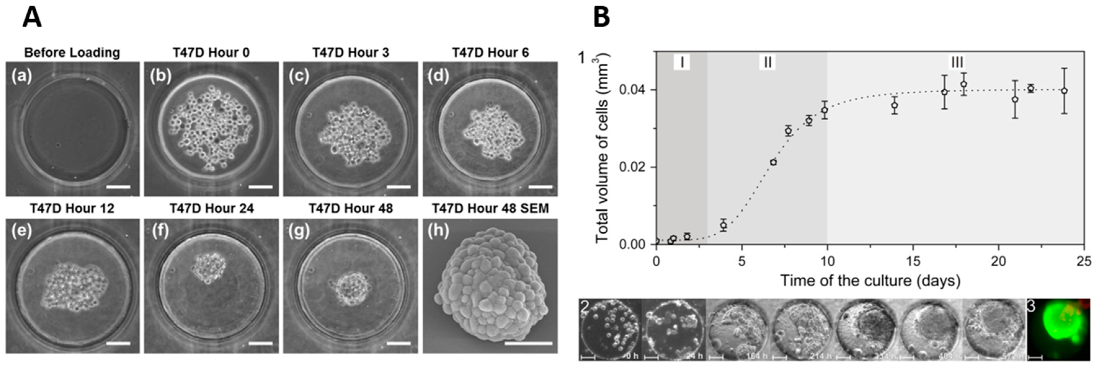
(A) The figure shows the first phase in which T47D breast cancer cells aggregate to become a spheroid in 48 h (scale bar: 100 μm) (a–g); A scanning electron microscopy (SEM) of the tumour spheroid portrays its compactness and roundedness (scale bar: 50 μm) (h). Reproduced with permission from [7] under a Creative Commons Attribution 4.0 International License from Scientific Reports; (B) HT-29 human carcinoma cell spheroid growth on a chip. (1) The curve shows spheroid total volume with respect to time while distinguishing spheroid living phases with the colours; (2) A microwell containing cells for spheroid formation. Reproduced with permission from [32] Copyright © 2012 Elsevier B.V.
Figure 2.
(A) The figure shows the first phase in which T47D breast cancer cells aggregate to become a spheroid in 48 h (scale bar: 100 μm) (a–g); A scanning electron microscopy (SEM) of the tumour spheroid portrays its compactness and roundedness (scale bar: 50 μm) (h). Reproduced with permission from [7] under a Creative Commons Attribution 4.0 International License from Scientific Reports; (B) HT-29 human carcinoma cell spheroid growth on a chip. (1) The curve shows spheroid total volume with respect to time while distinguishing spheroid living phases with the colours; (2) A microwell containing cells for spheroid formation. Reproduced with permission from [32] Copyright © 2012 Elsevier B.V.

Figure 3.
HD methods: (A) conventional HD method implemented in a Petri dish in which droplets are hanging from the lid; The Image was taken at Sharif Stem Cell Laboratory; (B) HD spheroid culture in a HD plate: (a) introduction of the cell suspension within the holes; (b) formation of the droplet by the capillary forces; (c) creation of an HD; (d) cell aggregation; (e) spheroid formation after one day. Redrawn with permission from [52] Copyright © 2010, Royal Society of Chemistry; (C) a HD-based µSFC. The figure depicts the pneumatic chamber being pressurized (1) to promote the flow from the central HD to the right HD (2); The left valve which prevented backflow, is now open while the pneumatic chamber is unpressurized (3); Part (4) shows the spheroids in the HDs; (5) An image of the HD based µSFC. Reproduced with permission from [54] Copyright © 2015, Royal Society of Chemistry; (D) a HD based µSFC integrated with a concentration gradient generator (CGG) whose cell loading ports are distinct from its drug inlet (a); (b) The image depicts the cell loading channels (using four colours) and the concentration gradient generated on the chip (using green). Reproduced with permission from [30] Copyright © 2014, Springer Nature.
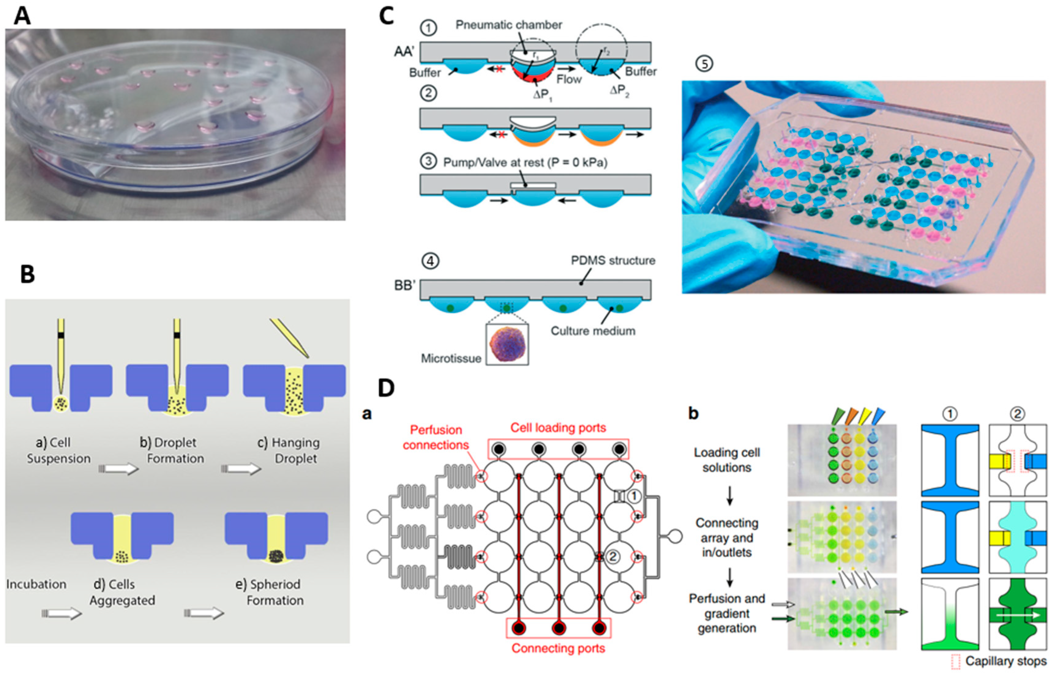
Figure 4.
Spheroid formation process in a microwell-based µSFC: (A) Introduction of a cell suspension to the chip inlet. The cell suspension fills all the microchannels and microwells rapidly due to the capillary effect; (B) Cells start depositing on the bottom of the microchannels and microwells; (C) Pure culture medium flows through the chip to rinse the excess cells without disturbing the cells lying on the microwell bottom; (D) Cell secretions and signalling lead to establishment of cell-cell interactions on the non-adherent microwell bottom; (E) Driving spheroid formation under a perfusing flow of culture medium. Reproduced with permission from [13] Copyright © 2018 Elsevier B.V.


Table 1.
The table is considered to represent the key variable elements in µSFCs and µSCCs. Those marked with * sign are µSCCs.
Table 1.
The table is considered to represent the key variable elements in µSFCs and µSCCs. Those marked with * sign are µSCCs.
| Reference | Year | Cell Type | Channel Dimensions | Hydrogel Type | Spheroid Formation Time | Spheroid or Droplet Diameter (µm) | Cells in Each Spheroid | Cell Density (cells/mL) | Media Flow Rate | 3D Culture Formation Method | Standard Deviation of Spheroid Size | Throughput |
|---|---|---|---|---|---|---|---|---|---|---|---|---|
| McMillan et al. [126] | 2016 | human glioblastoma cell line (UVW) | - | Alginate | Less than one day | - | - | 3 × 10⁶ | The medium was refreshed every 2 days | Single emulsion CS/O | - | 48 |
| McMillan et al. [83] | 2016 | UVW | - | - | 24 h | 300–575 | 500–1500 | 5 × 10⁶ | Daily Refreshment | Single emulsion CS/O | - | 2000 |
| Wang et al. [85] | 2014 | human cervical carcinoma (HeLa) | - | Alginate and Matrigel | 4 days | - | - | 107 | - | Double Emulsion CS/O and Gel/O | - | - |
| Sabhachandani et al. [63] | 2016 | breast cancer cell lines (MCF-7) and fibroblast cell lines (HS-5) | - | Alginate | 3 to 4 h | 170 (optimum) | - | 107 (mono) 7.5 × 10⁶ (co) | 20 μL/h (equivalent to 230 μm/s) | Single emulsion O/Gel | - | 1000 |
| Chan et al. [18] | 2013 | mesenchymal stem cells, HepG2, PMEF and Caco-2 | - | alginate | 150 min | 36 to 84 | - | 2, 5, 10 and 20 million cells/mL | - | Double emulsion CS/O/CM | - | - |
| Yu et al. [86] | 2015 | MCF-7 | - | alginate | - | 183 | - | 107 | - | Double Emulsion CS/Gel/O | 4% | - |
| Yu et al. [64] | 2010 | LCC6/Her-2 breast tumour cells | - | alginate | 4 days for spheroid and | 250 | 100 | 107 | 0.25 µL/min | Single emulsion CS/O and Gel/O | - | 28 |
| Alessandri et al. [82] | 2013 | CT26 mouse colon and HeLa cells and murine sarcoma S180 | - | Collagen, alginate | - | 100–150 | - | - | - | Double Emulsion CS/IS/Gel | - | 1000 droplet/s |
| Yamada et al. [58] | 2015 | NIH-3T3 cells and HepG2 cells | diameter = 200 μm, depth = 300 μm | Collagen I | 1 day | - | - | 2 × 10⁵ | - | Flat bottom microwells | - | - |
| Liu et al. [96] | 2015 | human glioma (U251) cells | - | - | - | 120–200 after 10 days | 200–400 | 5 × 10⁶ | at a very slow perfusion rate (5 μL/min) | U-shaped microstructures | - | 360 |
| Wu et al. [93] | 2008 | MCF-7 breast tumour cells | - | - | 7 to 11 h | 50 | 10 | 106 | 0.05~10 μL·min−1 (0.02 to 4 mm/s) | U-shaped microstructures | - | 7500 per cm2 |
| Shin et al. [65] | 2013 | MCF-7 breast tumour cells | - | matrigel and a gelatin hydrogel | 3 days | 50 | Less than 20 | 106 | 30 µL/h, equivalent to 278 µm/s | Cell suspension 50 µm wells (50 µm height) | - | - |
| Albanese et al. [127] | 2013 | MDA-MB-435 cells | - | - | 3 days | 260–280 | 750–1500 | - | 50 and 450 mL/h produced a 75–675 mm/s fluid velocity | Hanging droplet plates | - | - |
| Kwapiszewska et al. [87] | 2014 | HT-29 colon carcinoma and Hep-G2 liver carcinoma | - | - | 48 h | Almost 50 | - | 1–5 × 10⁶ | 4.5 μL/min for 15 min daily | in hemispherical bottom micro wells | Up to 30% | 216 |
| Aung et al. [28] | 2016 | human umbilical HUVECs and MCF-7 breast tumour cells | - | gelatin methacrylate (GelMA) | 20 h | 200 | - | - | 10 to 40 μL/h | In Petri dish and cultured on an orbital shaker | - | - |
| Ruppen et al. [25] | 2015 | lung adenocarcinoma + malignant pleural mesothelioma+ pericytes | Micro-well diameter: 500 µm Well height: 600 µm | - | 48 h | 325 and 210 | 1250 312 | - | Changed once a day | Cell sedimentation in round and flat-bottom wells in the chip | 35 to 45 µm | 8 in each unit |
| Jin et al. [91] | 2010 | non-small lung cancer cells, H1650 | - | - | 24 h | 197 | - | - | - | U-shaped microstructures | 11.7 micron | 4 |
| Torisawa et al. [26] | 2007 | MCF-7, HepG2 | - | - | 2 days for MCF-7 and 3days for HepG2 | - | 370 for HepG2 with 3 × 10⁶ | 1, 3, 10 × 106 | - | Pyramidal structures which have a hole at their vertex | - | 16 |
| Kim et al. [118] | 2015 | Human colorectal tumour and Primary rat liver | - | - | - | 180 | 250 | - | 13 µL/min. hydrostatic | Hanging droplet of Human colorectal tumour | - | 8 |
| Ziółkowska et al. [32] | 2013 | HT-29 human carcinoma cells | Well: 200, 150 Channel: 50, 1000 | - | 48 to 72 h | - | 100 | 1.5 × 10⁶ | 4.5 µL/min | Flat bottom microwells | not exceeding 20% in cell numbers | 45 |
| Lee et al. [33] | 2013 | Hepatocytes and hepatic stellate cells (HSCs) | Well: 500, 400 | - | - | 200 to 375 | - | 2 × 10⁶ | 5.53 mm/h or approximately 1.5 µm/s | Concave bottom microwells | - | 50 |
| Choong Kim et al. [79] | 2011 | mouse embryonic carcinoma | - | - | 3 day | 158 | 178 | 5 × 10⁵ | 0.2 mL/h for cell seeding | Flat bottom Microwell trapping | 4.50% | 60 |
| Ota et al. [23] | 2010 | Human hepatocellular liver carcinoma cells | - | - | 120 s | 130–430 µm | 1000 for 180 micron spheroid | 6.9 × 10⁶ | 0.4 ± 0.05 mL/min. | microrotation | 13.2% in 150–200 µm and 17.2% in 130–430 µm | 1 |
| Choong Kim et al. [128] | 2012 | MCF-7 | - | - | 3 days | 188 | 200 | - | 0.2 mL/h for cell seeding | Flat bottom Microwell trapping | 6.06 µm | 80 |
| Ota et al. [94] | 2011 | Hep-G2 | - | - | 120 s | 134 ± 25, 180 ± 30 and 237 ± 40 µm | - | 2–5–13 × 106 | 1.2 mL/min | microrotation | 18.7%, 16.6% and 16.9% | 15 |
| Ota et al. [59] | 2011 | Hep-G2 and endothelial cells | - | collagen | 120 s | 97–226 | - | 145, 290, 480 and 675 × 104/mL | 1.2 mL/min | microrotation | 17%, 18.7%, 16.6% and 16.9% | 15 |
| Patra et al. [8] | 2016 | human hepatocellular carcinoma cells (HepG2) | Chanel: 250 | - | 24 h | 130 and 212 | - | - | 100 µL/min for cell seeding and changed every 12 h by adding 1 mL of fresh culture media | Flat bottom well | 6% for small and 3% for large spheroids | 5000 |
| Well: 200 × 200 × 250 and 300 × 300 × 250 | ||||||||||||
| Kangsun Lee et al. [21] | 2012 | human embryonic kidney 293 cells (HEK 293) | - | - | Less than one day | Less than 300 µm for retrieval | - | 1–2–4 × 10⁶ | - | sedimentation | 5.5%, 7.2% and 8.9% for 1, 2 and 4 × 10⁶ | 50 |
| Kuo et al. [129] | 2012 | human epithelial ovarian cancer cells (SKOV3) | - | - | 48 h | 75 | - | 1.5 × 10⁴ | Hydrostatic flow for trapping and media change for culture | Trapping behind a porous membrane | Min of 7.6% | - |
| Patra et al. [88] | 2013 | murine ES cell, HepG2, African green monkey kidney epithelial fibroblast (COS-7) | Channel: 150, 1400, 25,000 Well: 200 × 200, 250 | - | 24 h for COS-7, 1 day for HepG2, 16 h for ES | COS-7 and HepG2 spheroids are 80 and 200 µm | - | HepG2 and COS-7 cell 107 and 105 respectively | 1 µL/min for cell seeding and 20 µL/min for culture refreshment every 48 h | Flat bottom well | standard deviations of 4 and 10 µm, respectively | 5000 |
| Chen et al. [7] | 2015 | T47D, MCF-7 and SUM159 (breast cancer) | Channel: 100 Well: 250, 400 and 450, 400 | - | 1 day | - | - | 5 × 10⁶ | 300 μL per minute for cell seeding | Flat bottom well | 10% | 1024 within an area of 2 by 2 cm |
| Yongli Chen et al. [24] | 2015 | HCT116, T47D breast cancer and HepG2 | Channel: 100, 3000, 9500 Well: 500, 200 | - | 24 h | - | - | 106 | - | Flat bottom well | - | 120 |
| Choi et al. [103] | 2016 | Hepatocytes | Channel: 100, 4000 | - | - | - | - | 1 × 10⁶ | 4.2 µm/(0.12 µL/min) | Concave bottom microwells | - | 50 |
| Robillard et al. [130] | 2016 | ovarian cancer cell line OV90 | Channel: 500, 2000 Well: 450 × 450 × 500 | - | - | 170 | - | 5 × 10⁵ cells/mL | The medium was changed Each day | Flat bottom microwells | - | 120 |
| Anada et al. [131] | 2010 | Human osteosarcoma MG63, HepG2 | Well: 1000, 500 | - | 1 day | 150 to 320 after 5 days of culture | - | 1.25 × 10⁵ to 8 × 10⁶ | - | Pneumatic concave wells | 5–8% | 1535 |
| Fukuda and Nakazawa [22] | 2011 | Hepatocytes of Wistar rat | Open Channel: 100, 100 Well: 300, 400 | - | 2 day | 150 | - | 2.5 × 10⁶ | - | Flat bottom microwells | - | 1575 |
| Xu et al. [95] | 2012 | P19 cells | - | - | 1 day | 100 to 450 | - | 2–20 × 104 cells mL−1 | 2 mm/ to rinse excess cells, 6 or 0.5 mm/sec for spheroid retrieval | Concave bottom microwells | - | 880 |
| Zhang et al. [97] | 2009 | BALB/3T3 (murine embryonic fibroblast) cell line. | - | - | - | 90 | 85 ± 6.3 | 107 | 1 µL/min for 10 min every 6 h | U-shaped microstructures | - | 512 totally (8 in each chamber) |
| Chien-Yu Fu et al. [90] | 2014 | HepG2 and Balb/c 3T3 fibroblast cells | - | - | 1 day | - | - | 8.4 × 10⁶ | 1.5 µL/min for long-term perfusion | U-shaped microstructures | - | 56 |
| Tung et al. [52] | 2011 | COS7, ES-D3 and human epithelial carcinoma cell | - | - | 1 day | - | 300, 1500 and 7500 | - | - | Novel Hanging droplet method (3d-biomatrix, perfecta 3d) | - | 384 |
| Santo et al. [42] | 2016 | MCF7, H1650, H157, HT29, Human Dermal Fibroblasts (hDFs) | - | - | - | 100 to 800 | - | 0.2 × 10⁶ & 0.5 × 10⁶ | - | Stirred tank | Up to about 40% | - |
| Torisawa et al. [132] | 2009 | Fibroblast COS-7; HepG2; ATCC; Breast cancer MDA-MB-231 | - | - | - | - | - | 105 | Hydrostatic-driven flow, medium daily exchanged | Patterning on semi-porous membranes | - | - |
| Hsiao et al. [105] | 2009 | prostate cancer cells osteoblasts and endothelial cells | - | - | 1 day | 86 | - | - | Hydrostatic-driven flow, medium daily exchanged | Patterning on semi-porous membranes | 12 µm | 28 |
| Chen et al. [104] | 2016 | HEK 293, SH-FY5Y, HepG2 and HeLa cells | - | - | 1 day | 30 to 100 | - | 2–17 × 106 | medium daily exchanged in Petri dish | Acoustic tweezers | - | 150 |
© 2018 by the authors. Licensee MDPI, Basel, Switzerland. This article is an open access article distributed under the terms and conditions of the Creative Commons Attribution (CC BY) license (http://creativecommons.org/licenses/by/4.0/).
Share and Cite
MDPI and ACS Style
Moshksayan, K.; Kashaninejad, N.; Saidi, M.S. Inventions and Innovations in Preclinical Platforms for Cancer Research. Inventions 2018, 3, 43. https://doi.org/10.3390/inventions3030043
AMA Style
Moshksayan K, Kashaninejad N, Saidi MS. Inventions and Innovations in Preclinical Platforms for Cancer Research. Inventions. 2018; 3(3):43. https://doi.org/10.3390/inventions3030043
Chicago/Turabian StyleMoshksayan, Khashayar, Navid Kashaninejad, and Mohammad Said Saidi. 2018. "Inventions and Innovations in Preclinical Platforms for Cancer Research" Inventions 3, no. 3: 43. https://doi.org/10.3390/inventions3030043