Development of a Dung Beetle Robot and Investigation of Its Dung-Rolling Behavior


Mechanical Engineering, National Taiwan University, Taipei 10617, Taiwan
*
Author to whom correspondence should be addressed.
†
These authors contributed equally to this work.
Inventions 2018, 3(2), 22; https://doi.org/10.3390/inventions3020022
Submission received: 27 February 2018
/
Revised: 3 April 2018
/
Accepted: 4 April 2018
/
Published: 10 April 2018
(This article belongs to the Special Issue Selected Papers from ICI2017 and Spintech Thesis Awards)
Abstract
:In this study, a bio-inspired dung beetle robot was developed that emulated the dung rolling motion of the dung beetle. Dung beetles, which can roll objects up to 1000 times their own body weight, are one of the strongest insect species in the world. While the locomotion of many insects, such as cockroaches, inchworms, and butterflies, has been studied widely, the locomotion of dung beetles has rarely been given attention. Here, we report on the development of a dung beetle robot made specifically to investigate dung-rolling behavior and to determine and understand the underlying mechanism. Two versions of the robot were built, and the leg trajectories were carefully designed based on kinematic analysis. Cylinder and ball rolling experiments were conducted, and the results showed that the dung beetle robot could successfully and reliably roll objects. This further suggests that the dung beetle robot, with its current morphology, is capable of reliably rolling dung without the need for complex control strategies.
1. Introduction
Research into bio-inspired robots has developed rapidly over the past twenty years as the quality of motors, sensors, and processors has improved. Some of these robots are even autonomous and can maintain a high degree of stability and reliability. The concept behind bio-inspired robots is to learn from nature, particularly in terms of the morphology, control, and locomotion of biological systems, and to apply the extracted principles to engineering solutions. Bio-inspired robots have many potential applications in areas, such as education, entertainment, the military, and rescue operations. They have become one of the most prominent aspects of robotics.
A wide range of bio-inspired robots has been developed with many different focuses, and insects are one of the inspiration sources. For example, RHex is a hexapod robot inspired by the locomotion of cockroaches. Although RHex has only one active rotational degree of freedom (DOF) per leg, it can perform various actions, such as walking [1], running [2], stair climbing, bar and step climbing [3], self-righting [4], and leaping [5]. A simplified version, ToyRHex, which employs a single direct current (DC) motor with a noncircular gear transmission to drive all six legs, can both walk and run [6]. The Sprawl series was also inspired by cockroach locomotion, but was designed through a different approach. Sprawlita uses linear pneumatic actuators as the driving force and servo motors to control the leg configuration [7]. Later, iSprawl replaced the pneumatic actuators with a DC motor and a crank-slider mechanism to achieve autonomous power [8]. MantisBot developed by Quinn et al. imitates the mantis, and is controlled by a high-fidelity neural simulation. It has 28 DOFs to implement directed behavior, such as prey tracking and striking [9]. Robot II, also developed by Quinn et al., is an 18 DOF hexapod robot inspired by the locomotion of the locust. It can perform simultaneous lateral, rotational, and forward or backward walking, while also successfully negotiating irregular terrain using a combination of active compliance, postural control, searching behavior, and an elevator reflex [10]. HExapod Cognitive auTonomously Operating Robot (HECTOR) developed by Schneider et al. is a six-legged robot consisting of 18 embedded, custom-designed, and compliant joint drives based on an integrated elastomer coupling. It can move all six legs independently, react to its surroundings, and learn from experience [11,12]. Octavio, developed by von Twickel et al., consists of single, energy- and control-autonomous legs with three DOFs and is inspired by Carausius morosus. Its legs are especially robust when compared with most other walking machines. Further, it is based on the concept of cybernetically-equivalent processes in biology and technology [13]. AMOS II developed by Manoonpong et al. imitates cockroaches and stick insects, generating basic walking behavior and effectively performing reactive climbing behavior [14].
A wide range of insect-inspired research studies focusing on robotic emulations have been published but, to the best of our knowledge, there is no relevant literature about dung beetle’s locomotion. Therefore, we were motivated to explore dung rolling from a robotic aspect. The goal of this research is to explore the possibility of designing a robot that can execute a steady ball-rolling motion through simple mechanisms and control strategies.
From the above mentioned insect-inspired robots, we can see locomotion is the main point in hexapod robots. Some use simple mechanisms to perform a specific action, while others build a sophisticated control strategy to manipulate multiple degrees of freedom. Here, by observing the diversity in robot design, we determine to seek a simplified method to achieve our goal.
2. Materials and Methods
2.1. Observation
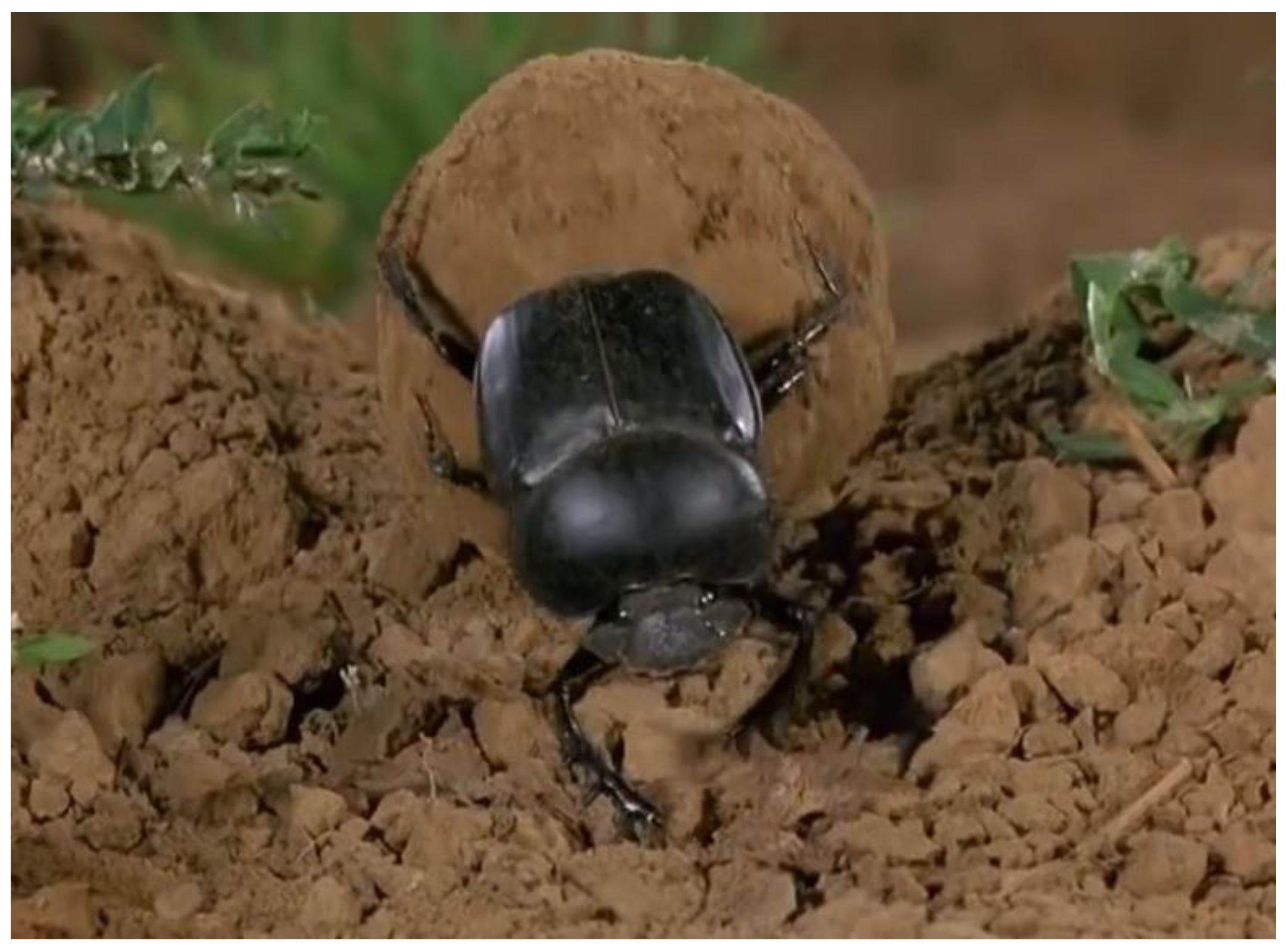
Figure 1 shows the locomotion and body structure of the dung beetle [15], which rolls dung by posing its body upside down. This makes sense for two reasons:
- The weight of the beetle can be steadily supported by the forelegs, which are short and strong.
- The ball of dung can be easily manipulated by the long mid- and hind-legs, which have spines that help to grasp the soft dung.
In addition, when the dung beetle rolls a dung ball, for stable manipulation, it always uses at least two legs, a mid-leg and hind-leg, on opposite sides of the body to hold the ball of dung.
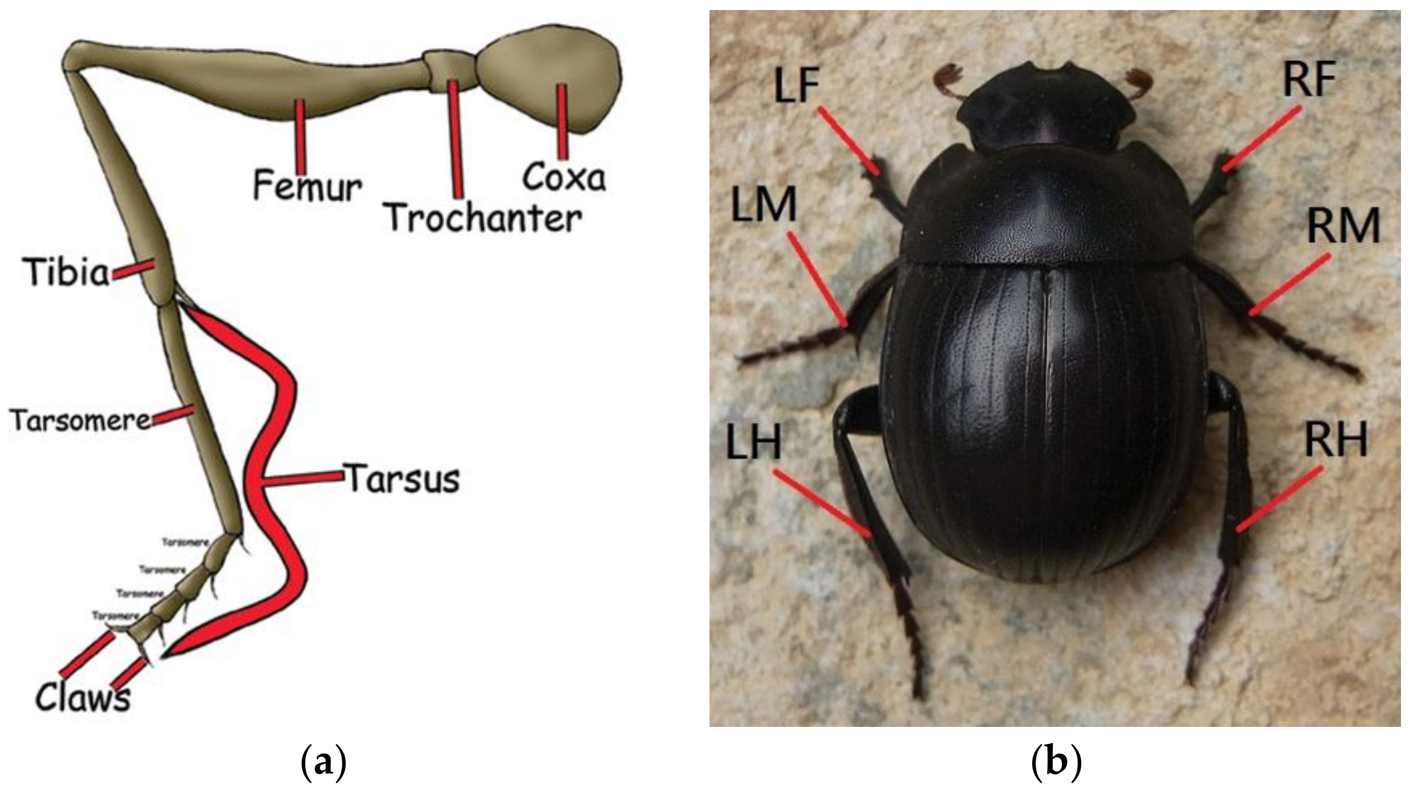
As a normal insect, the leg of the dung beetle is comprised of five major segments: coxa, trochanter, femur, tibia, and tarsus, as shown in Figure 2a. In the remainder of this paper, the abbreviated form of each leg is used, as shown in Figure 2b: LF for left foreleg, LM for left mid-leg, LH for left hind-leg, RF for right foreleg, RM for right mid-leg, and RH for right hind-leg.
The main scope of this research work is to develop a robot that can roll a sphere forward steadily without a sensing unit. The body structure is inspired by the dung beetle, and the specification is listed in Table 1. The robot body has dimensions of 180 mm × 160 mm, which accommodates the control unit and power supply. The control program is built by the LabVIEW FPGA module (National Instruments, Austin, TX, USA), and the controller is an NI myRIO embedded system (National Instruments, Austin, TX, USA). The servomotors are connected to the controller through the breakout board. The power is supplied by an 1100 mAh lithium polymer battery. The claws are fabricated using 3D printing, with Polylactic acid (PLA) material.
2.2. Robot Morphology Design
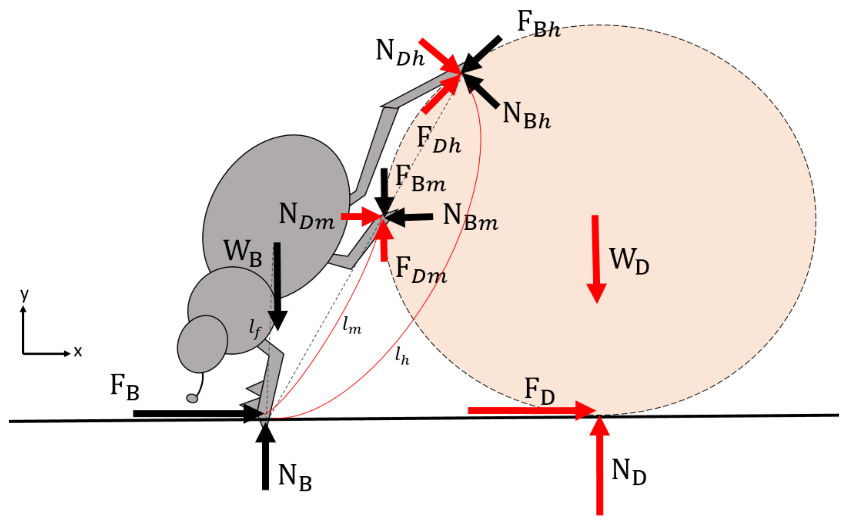
Dung rolling is comprised of two sub-motions: the forward thrust provided by the forelegs, and control of the rolling motion by the mid- and hind-legs. To investigate the simplest pattern of its movement, we simplified the spatial dung rolling by making it a sagittal planar problem. The free-body diagram is shown in Figure 3.
The static equations for the dung beetle are as follows:
The forces acting on the mid-leg are not necessary to obtain static equilibrium. Therefore, the first robot we built (Figure 4) was achieved as follows:
- The dung-ball was replaced by a cylinder. Due to the line contact with the ground, the rolling was close to pure rolling, and the direction could easily be kept constant.
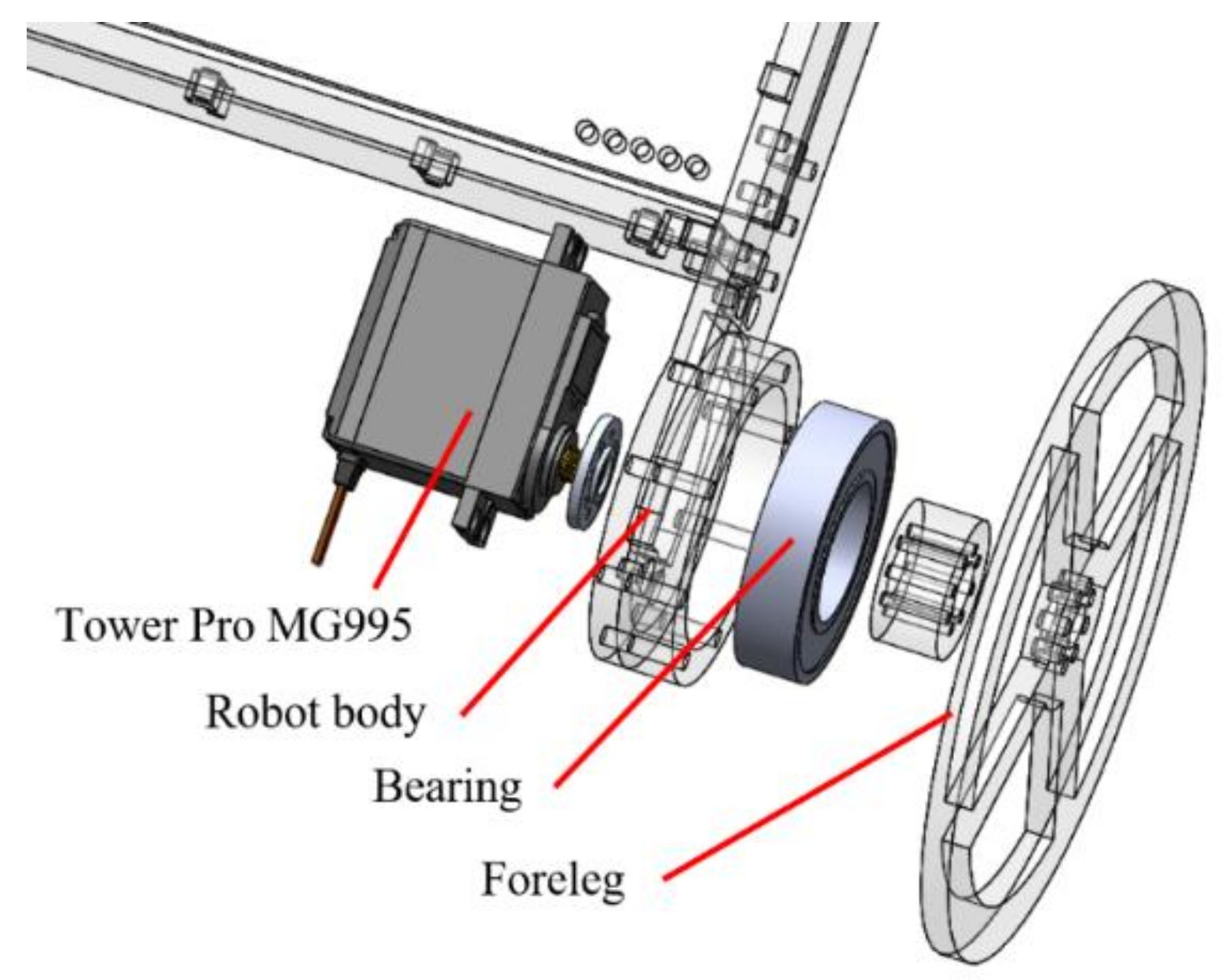
- The forelegs were replaced by circular wheels (Figure 5). The robot had two possible foreleg ground contact points and two cylinder contact points through the other two legs. However, rolling of the cylinder was unstable because sometimes two hind-legs were not in contact with the ground, which was necessary for stability. Use of the fully-uninterrupted wheel meant that foreleg contact with the ground was continuous. In such a case, even if the other legs rolled the cylinder alternatively, the robot would always have three contact points to ensure stable body posture.
- In the early stage of robot development, ball-rolling was simplified to cylinder-rolling, and the motion projections of these two cases on the sagittal plane were indeed identical. For simulation, a model composed of two legs and one wheel was indeed a better choice. However, for empirical robotic implementation, the robot required a certain width to make its sagittal-plane forward motion feasible. In addition, one leg on the cylinder was sufficient to roll the cylinder. Thus, instead of using a middle leg and a hind leg, the robot was designed to have two hind legs and two wheels, which are leg LH/RH and LF/RF.
- Since the leg had no control over the orientation of the claw, the foot was needle-shaped with a small ball at the end to give it point contact with the simulated dung (the cylinder).
We set up an experiment to test the rolling motion of the robot. The cylinder was replaced by a water bottle. The robot motion sequence is illustrated in Figure 6. The experimental results show that the robot was able to roll a cylinder steadily forwards. The robot could also passively adjust its body orientation so that the start and end position of the legs on the cylinder were properly aligned to provide rolling force to the cylinder. Although planar rolling motion had been achieved, the robot could not roll a ball because the alternating rolling motion of the legs RH and LH caused the ball to spin and move sideways. Simultaneous rolling force on both sides of the ball was required to make ball rolling feasible.
2.3. Planning the Dung Rolling Motion
The robot was able to perform different steady ball rolling motions, but the simplest of these was achieved by assuming that both the robot and the ball move at the same constant speed. In this case, the foot trajectory relative to the robot body was a simple arc. By using inverse kinematics, the joint angles of the legs could be analytically derived from the known radius of the ball and other parameters, such as the relative configuration between the robot and the ball.
The rolling motion of the robot leg can be divided into four stages, as shown in Figure 9a. The associated timing diagram is shown in Figure 9c; the diagram includes the motion of either a pair of mid-legs or hind-legs. The starting point and the range where the legs roll the ball need to be set appropriately. The sequence of the rolling motion is described as follows:
- Initially, the legs were placed at the red triangles shown in Figure 9a, which are close to the starting and end points. For demonstration purposes, assume the leg placed close to the starting point is leg RH, and the other is leg LH.
- As the rolling motion starts, leg RH moves along track ①, and leg LH moves along track ③. At this stage, both hind-legs are holding the ball, so the ball rolls steadily.
- When leg RH begins moving along track ②, leg LH is lifting from the end point and moving along track ④ towards the starting point. At this stage, the ball is rolled by only one leg of this pair.
- When leg RH moves along track ③, leg LH contacts the ball at the starting point and then moves along track ①.
- Leg RH lifts from the ball after reaching the end point, and then moves back to the starting point. Leg LH keeps moving along track ② at the same time.
When the mid-legs or the hind-legs roll the ball at its starting point, no radial/normal displacement should be applied to the ball, because this would not only roll the ball, but also push it away. Therefore, while the leg is in contact with the ball at the starting point, its motion must be in the tangential direction of the ball to provide only a rolling force. At the end point, it lifts vertically from the ball to avoid generating any disturbance to the rolling motion. After that, the foot moves along with an arc parallel to the ball surface. The precise trajectory of track ④ is shown in Figure 9b.
The gait pattern shown in Figure 9b can be applied to both mid- and hind-legs. These two pairs of legs are synchronized so that the opposite legs work simultaneously; more specifically, when the right hind-legs and the left mid-legs are in phase. This coordination of the mid- and hind-legs ensures that at least one leg on each side rolls the ball at every instant, thus providing steady and continuous tangential force to roll the ball. The leg motion sequence is illustrated in Figure 10.
2.4. Experimental Validation
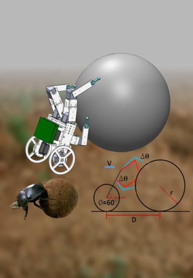
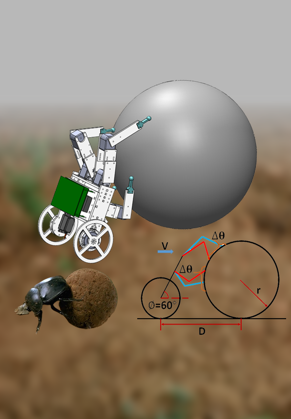
The dung beetle robot was built and used to perform ball rolling motion as the validation step for this bio-inspired engineering system. Here, the experimental results of the final dung beetle robot are reported. To collect the quantitative motion data of both the robot and the ball, markers were placed on both, as shown in Figure 11a, and the experiments were executed under a motion capture system composed of five high-speed cameras (T20s, VICON, Oxford, UK). At least three of these can capture the marker positions at any given moment. The robot (including its body and legs) and the ball were computed based on the three-dimensional coordinates of the markers. The parameters and settings used in the experiments are described as follows, and are shown in Figure 11b.
- The “simulated” dung: A ball was used and rolled by the robot.
- The radius of the rolling object (r): A basketball with a radius of 12.5 cm was used as the ball.
- Forward velocity (V): The forward velocity of both the robot and the ball were set at a constant 5 cm/s.
- Rolling range and the starting angle (∆θ) of the mid- and hind-legs: The rolling range was set to 30°. During the first and last 10°, the ball was rolled by four legs. During the middle 10°, the ball was rolled by two legs while the other two were in the air for repositioning.
- Body inclination (∅): when the robot rolls the ball, its body must incline on the ball to allow the mid- and hind-legs to have sufficient normal force to roll the ball. These legs also help to partially support the body weight. The body inclination was set at 60°.
- The distance between the robot body and the ball (D): This distance affects the leg trajectories. If the distance is too short, the leg trajectory may not be feasible due to tight space. In contrast, if it is too long, the ball is difficult to reach. The distance was set at 30 cm.
- Ball weight (W): we used a basketball, which weighed 650 g.
Two sets of experiments were conducted to evaluate the ball rolling performance of the dung beetle robot. Since the rolling range was the key factor influencing performance, two rolling ranges, namely 40°–70° and 50°–80°, were evaluated.
3. Results
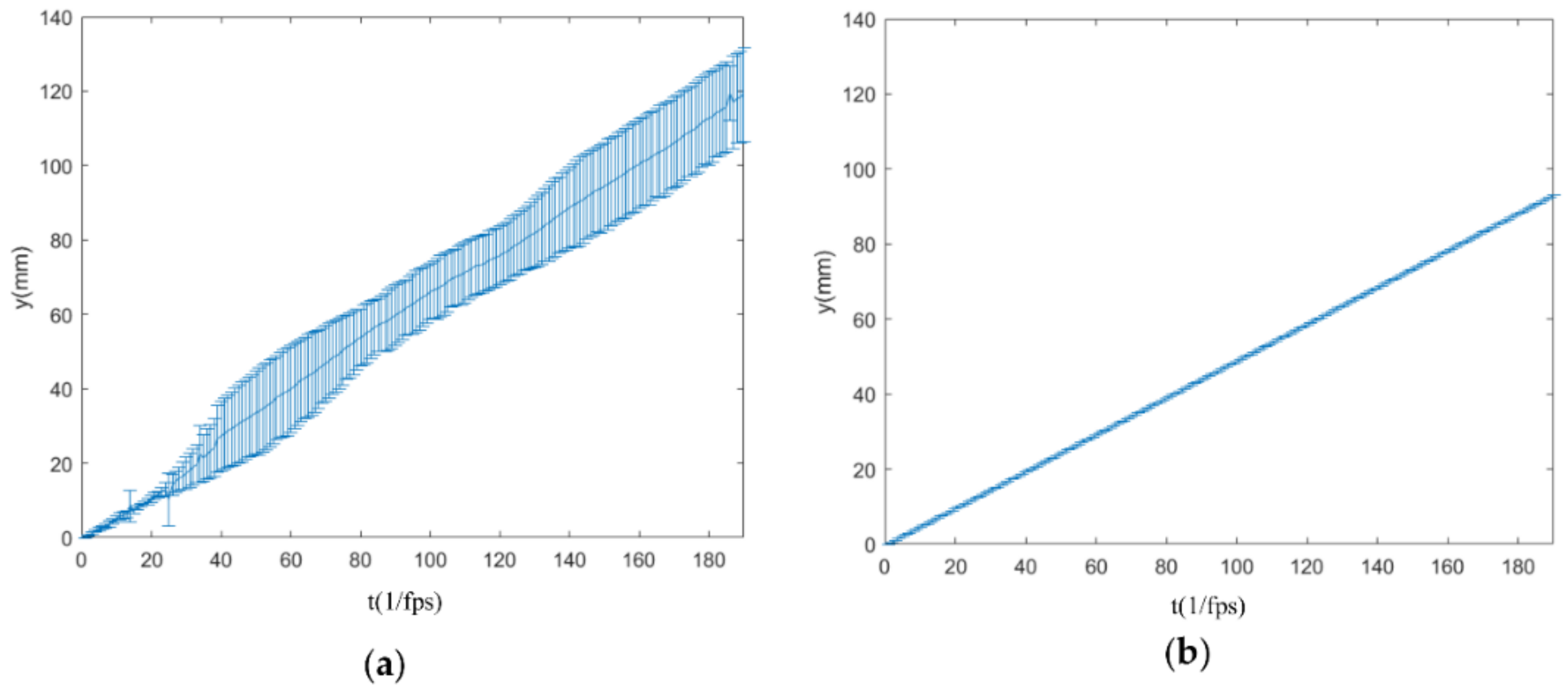
Figure 12 and Figure 13 show the planar center of mass (COM) trajectory of the ball at each leg motion loop described in Figure 10. The robot was set to roll the dung on multiple runs, and the experimental data were reorganized and analyzed per motion period. The mean and standard deviations of all the experimental data per step are presented by solid curves and error bars. Although the leg trajectories were pre-defined and open-loop without any sensory feedback, the robot seemed to be capable of stabilizing its rolling motion despite some deviation at each time step. From the observation of Figure 12 and Figure 13, the robot with a high rolling range (i.e., (b)) seems to be more stable than that with a low rolling range (i.e., (a)). This is because the robot leans on the ball more heavily at a high rolling range, and this seemed to make the ball more controllable.
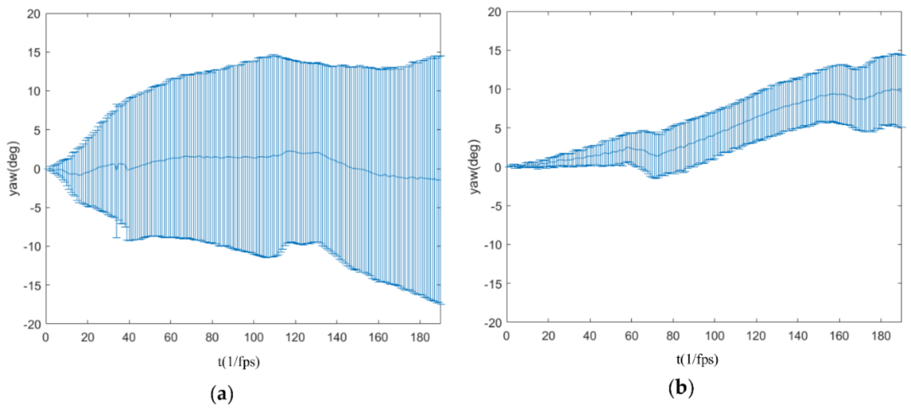
Figure 14 shows the yaw angle of the ball versus time at each leg motion loop. Similarly, the average and standard deviations of each time step are plotted by solid curves and error bars. The yaw angle can be regarded as an index for evaluating the balance of the rolling forces from the right and left legs. During the rolling motion, the yaw angles were maintained between −20° and 20° without causing the ball to rotate about a vertical axis in the same place.
Figure 15a is a top view of the planar COM trajectory of the robot body. The robot body moves forward stably regardless of the rolling range. Figure 15b shows the variation in body inclination of the robot as it rolled the ball. Ideally, if the foot makes contact and rolls the ball exactly as planned, the robot body should maintain a constant inclination angle. In reality, because the contact point may deviate from the ideal and slippage may occur during the roll, the body inclination changes. Due to this imperfect effect, rolling in the lower rolling range of 40°–70° had larger deviations (mean 56.1° and standard deviation 1.76°) than that of the higher range (mean 55.6° and standard deviation 0.82°).
4. Discussion
To summarize, the robot had fewer DOFs than the dung beetle for dung/ball rolling or manipulation, and the robot only had a simple control strategy for the rolling motion; however, the experimental results showed that the robot was still capable of rolling the ball without severe deviation from the planned trajectory. The current arrangement of the rolling force to the ball seems to be able to stabilize the motion of the system. In addition, in the higher rolling range, the robot seems to be more stable than in the lower range. We speculate that a dung beetle also searches for a higher rolling range to lean more heavily on the ball for more rolling stability.
The six-legged locomotive morphology evolved by insects is intrinsically robust and is easily adaptable to diverse environments by using the combination of feedforward and delicate sensory feedback strategies. On the robot side, the adequate feedback for robust locomotion, similar to that of insects, is still in the exploration stage. In the meantime, robots with a “preflex” level of the motion planning, such as RHex, can exhibit certain locomotion capability. Similarly, although the robot utilized in this experiment is extremely simple compared to an evolved dung beetle, the robot can indeed perform a basic rolling motion.
5. Conclusions and Future Work
In this study on the development of a dung beetle robot to simulate dung rolling motion, the robot went through two design iterations. In the first version, only sagittal plane rolling motion was considered, the dung was simulated by a cylinder, and the four mid- and hind-legs were represented by only two. The experiments showed that the robot could indeed roll the cylinder smoothly. To bring the scenario closer to reality, a second version of the robot was designed with a morphology with two wheels and four legs that was capable of using four mid- and hind-legs to roll a ball. The front legs were represented by two wheels that provided constant forward motion and thrust.
The quantitative experiments were conducted under a motion capture system to evaluate the performance of the robot. Various parameters were first set, such as forward velocity, rolling range, and body inclination angle. Two sets of experiments with the robot using different rolling ranges were evaluated. The results show that the robot was capable of rolling a ball on the flat terrain by using a simple pre-defined leg trajectory without the need for a feedback mechanism. Though the robot only rolled the ball on flat terrain, many uncertainties and empirical defects came into play (e.g., the robot dimensions and rigidity, the control accuracy (position, synchronization, etc.), the ball dimensions, and rolling/sliding). In addition, variations in the robot body inclination indicate that the setting is not perfect.
This development serves as the first step toward understanding the underlying mechanism of dung rolling by the dung beetle. Many interesting issues remain, such as obstacle avoidance, non-spherical dung, and rough terrain. We are currently moving forward to explore these unsolved issues.
Acknowledgments
We wish to thank our project advisor, Pei-Chun Lin from the Department of the Mechanical Engineering (ME), National Taiwan University (NTU), for steering us in the right direction and giving us valuable comments and suggestions. We would also like to thank all senior members and laboratory colleagues from the Bio-inspired Robotics Laboratory (BioRoLa) at ME, NTU, for all their valuable suggestions and advice. We would like to thank SpinTech Precision Machinery Co. Ltd., which provides the SpinTech Technology Thesis Awards and gave us the opportunity to publish our research results in the journal. This research was supported by the Ministry of Science and Technology (MOST), Taiwan, under project number MOST 103-2221-E-002-091-MY3.
Author Contributions
Yu-Sheng Chiang designed the robot structure. Hao-Hsun Hsu assisted the experiment. Jen-Wei Wang, and Yu-Sheng Chiang designed the control system. Jhih Chen installed the Printed circuit board and embedded device. All authors contributed to conducting the experiments. Jen-Wei Wang contributed to the data analysis. All authors contributed to the writing of the paper.
Conflicts of Interest
The authors declare no conflict of interest.
References
- Saranli, U.; Buehler, M.; Koditschek, D.E. RHex: A simple and highly mobile hexapod robot. Int. J. Robot. Res. 2001, 20, 616–631. [Google Scholar] [CrossRef]
- Huang, K.J.; Huang, C.K.; Lin, P.C. A simple running model with rolling contact and its role as a template for dynamic locomotion on a hexapod robot. Bioinspir. Biomim. 2014, 9, 046004. [Google Scholar] [CrossRef] [PubMed]
- Chou, Y.C.; Yu, W.S.; Huang, K.J.; Lin, P.C. Bio-inspired step-climbing in a hexapod robot. Bioinspir. Biomim. 2012, 7, 036008. [Google Scholar] [CrossRef] [PubMed]
- Saranli, U.; Rizzi, A.A.; Koditschek, D.E. Model-based dynamic self-righting maneuvers for a hexapedal robot. Int. J. Robot. Res. 2004, 23, 903–918. [Google Scholar] [CrossRef]
- Chou, Y.C.; Huang, K.J.; Yu, W.S.; Lin, P.C. Model-based development of leaping in a hexapod robot. IEEE Trans. Robot. 2014, 31, 40–54. [Google Scholar] [CrossRef]
- Huang, K.J.; Chen, S.C.; Komsioglu, H.; Lopes, G.; Clark, J.; Lin, P.C. Design and performance evaluation of a bio-inspired and single-motor-driven hexapod robot with dynamical gaits. J. Mech. Robot. 2015, 7, 031017. [Google Scholar] [CrossRef]
- Cham, J.G.; Bailey, S.A.; Clark, J.E.; Full, R.J.; Cutkosky, M.R. Fast and robust: Hexapedal robots via shape deposition manufacturing. Int. J. Robot. Res. 2002, 21, 869–882. [Google Scholar] [CrossRef]
- Kim, S.; Clark, J.E.; Cutkosky, M.R. iSprawl: Design and tuning for high-speed autonomous open-loop running. Int. J. Robot. Res. 2006, 25, 903–912. [Google Scholar] [CrossRef]
- Szczecinski, N.S.; Chrzanowski, D.M.; Cofer, D.W.; Terrasi, A.S.; Moore, D.R.; Martin, J.P.; Ritzmann, R.E.; Quinn, R.D. Introducing MantisBot: Hexapod robot controlled by a high-fidelity, real-time neural simulation. In Proceedings of the IEEE International Conference on Intelligent Robots and Systems, Hamburg, Germany, 28 September–2 October 2015; pp. 3875–3881. [Google Scholar]
- Espenschied, K.S.; Quinn, R.D.; Chiel, H.J.; Beer, R.D. Biologically-inspired hexapod robot project: Second robot. In Proceedings of the IEEE International Conference on Robotics and Automation (ICRA), Nagoya, Japan, 21–27 May 1995. [Google Scholar]
- Schneider, A.; Paskarbeit, J.; Schilling, M.; Schmitz, J. HECTOR, A Bio-Inspired and Compliant Hexapod Robot; Duff, A., Prescott, T., Verschure, P., Lepora, N., Eds.; Living Machines, LNAI 8608; Springer: Cham, Switzerland, 2014; pp. 427–429. [Google Scholar]
- Paskarbeit, J.; Schilling, M.; Schmitz, J.; Schneider, A. Obstacle crossing of a real, compliant robot based on local evasion movements and averaging of stance heights using singular value decomposition. In Proceedings of the IEEE International Conference on Robotics and Automation (ICRA), Seattle, WA, USA, 26–30 May 2015; pp. 3140–3145. [Google Scholar]
- Von Twickel, A.; Hild, M.; Siedel, T.; Pasemann, F. Octavio: Autonomous Legs for a Reconfigurable Walking Machine; HLR 2006, French-German Workshop on Humanoid and Legged Robots; Christian Simonidis: Karlsruhe, Germany, 2006. [Google Scholar]
- Goldschmidt, D.; Hesse, F.; Worgotter, F. Biologically inspired reactive climbing behavior of hexapod robots. In Proceedings of the 2012 IEEE/RSJ International Conference on Intelligent Robots and Systems (IROS), Vilamoura-Algarve, Portugal, 7–12 October 2012; pp. 4632–4637. [Google Scholar]
- Microcosmos—Dung Beetle Rolls Ball and Gets Stuck. Available online: https://www.youtube.com/watch?v=AHpIlS6F2g (accessed on 13 January 2013).
- Kerem, D. Insect Leg Segments; University of Sydney: Sydney, Australia. Available online: http://bugs.bio.usyd.edu.au/learning/resources/Entomology/externalMorphology/imagePages/leg_master.html (accessed on 6 February 2018).
- Gyronotus Perissinottoi. (n.d.) in Wikipedia. Available online: https://en.wikipedia.org/wiki/Gyronotus_perissinottoi (accessed on 6 February 2018).
Figure 1.
Dung rolling of the dung beetle [15].
Figure 1.
Dung rolling of the dung beetle [15].

Figure 2.
The body structure of a dung beetle: (a) the major leg segments of adult insects [16]; and (b) the abbreviations of dung beetle’s legs [17].

Figure 3.
Free body diagram of the dung beetle and dung. Red arrows indicate forces act on dung. Black arrows indicate forces act on beetle. : weight of the beetle, : weight of the dung, : ground friction acting on the beetle, : ground friction acting on the dung, : normal force acting on the beetle, : normal force acting on the dung, : friction acting on the beetle at the hind-leg, and : Normal force acting on the dung at the mid-leg.

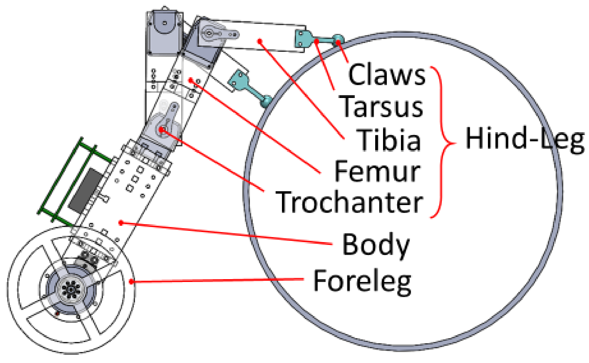
Figure 4.
The Computer-aided design (CAD) model (side view) of the first version of dung beetle robot.
Figure 4.
The Computer-aided design (CAD) model (side view) of the first version of dung beetle robot.

Figure 5.
An exploded view of the foreleg structure of the dung beetle robot.

Figure 6.
The motion sequence of the first version dung beetle robot rolling a cylinder.

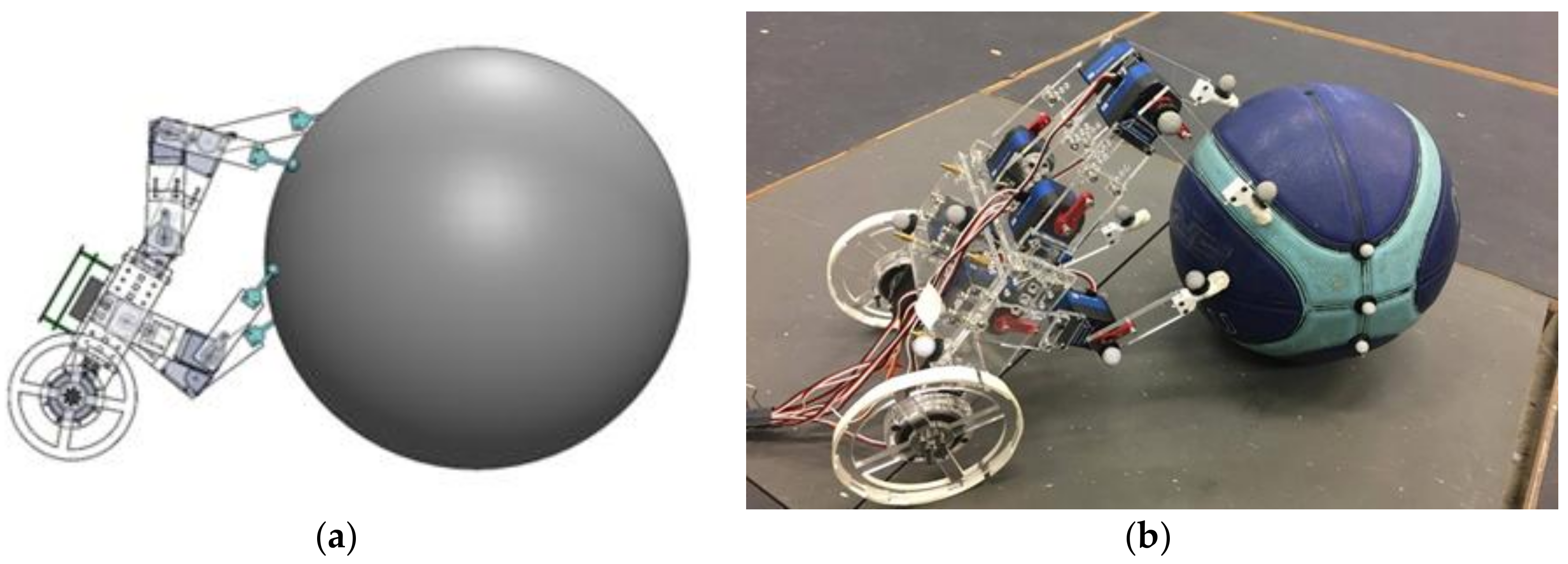
Figure 7.
The second version of the dung beetle robot: (a) CAD drawing (side view); and (b) photograph.
Figure 7.
The second version of the dung beetle robot: (a) CAD drawing (side view); and (b) photograph.

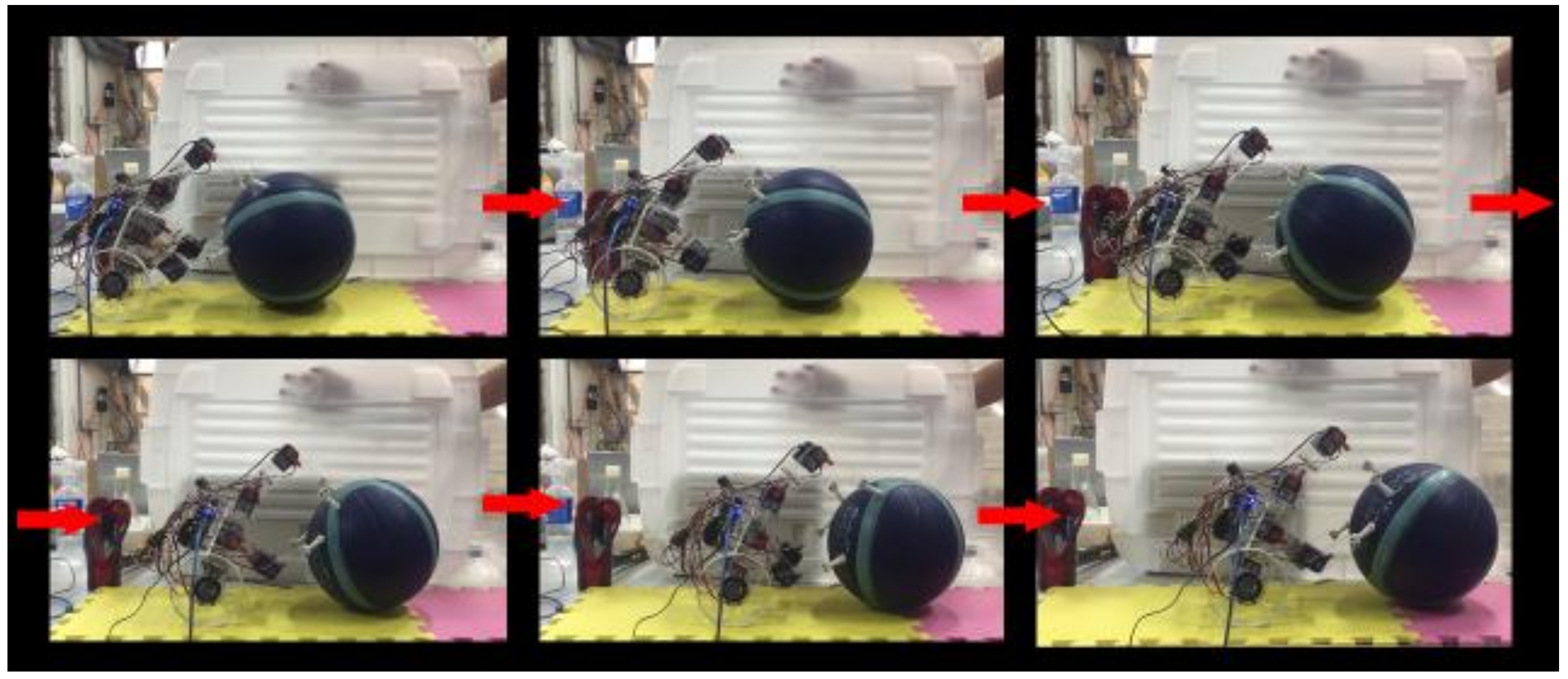
Figure 8.
The motion sequence of the dung beetle (second version) robot rolling a ball.

Figure 9.
Trajectory planning of the robot legs: (a) the leg trajectory on the ball has four stages. Red triangles show where both legs are initially placed; (b) the side view of the leg trajectory; and (c) the timing diagram of a pair of either mid- or hind-legs.
Figure 9.
Trajectory planning of the robot legs: (a) the leg trajectory on the ball has four stages. Red triangles show where both legs are initially placed; (b) the side view of the leg trajectory; and (c) the timing diagram of a pair of either mid- or hind-legs.
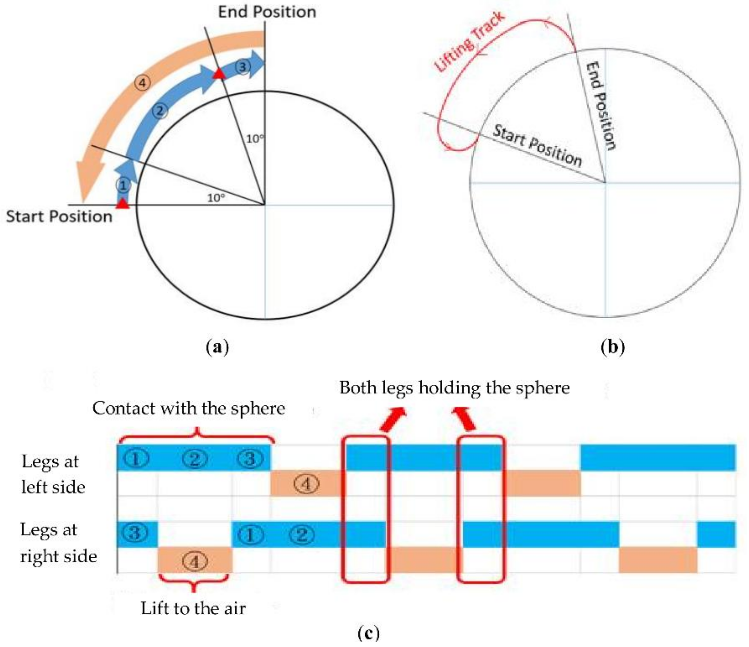
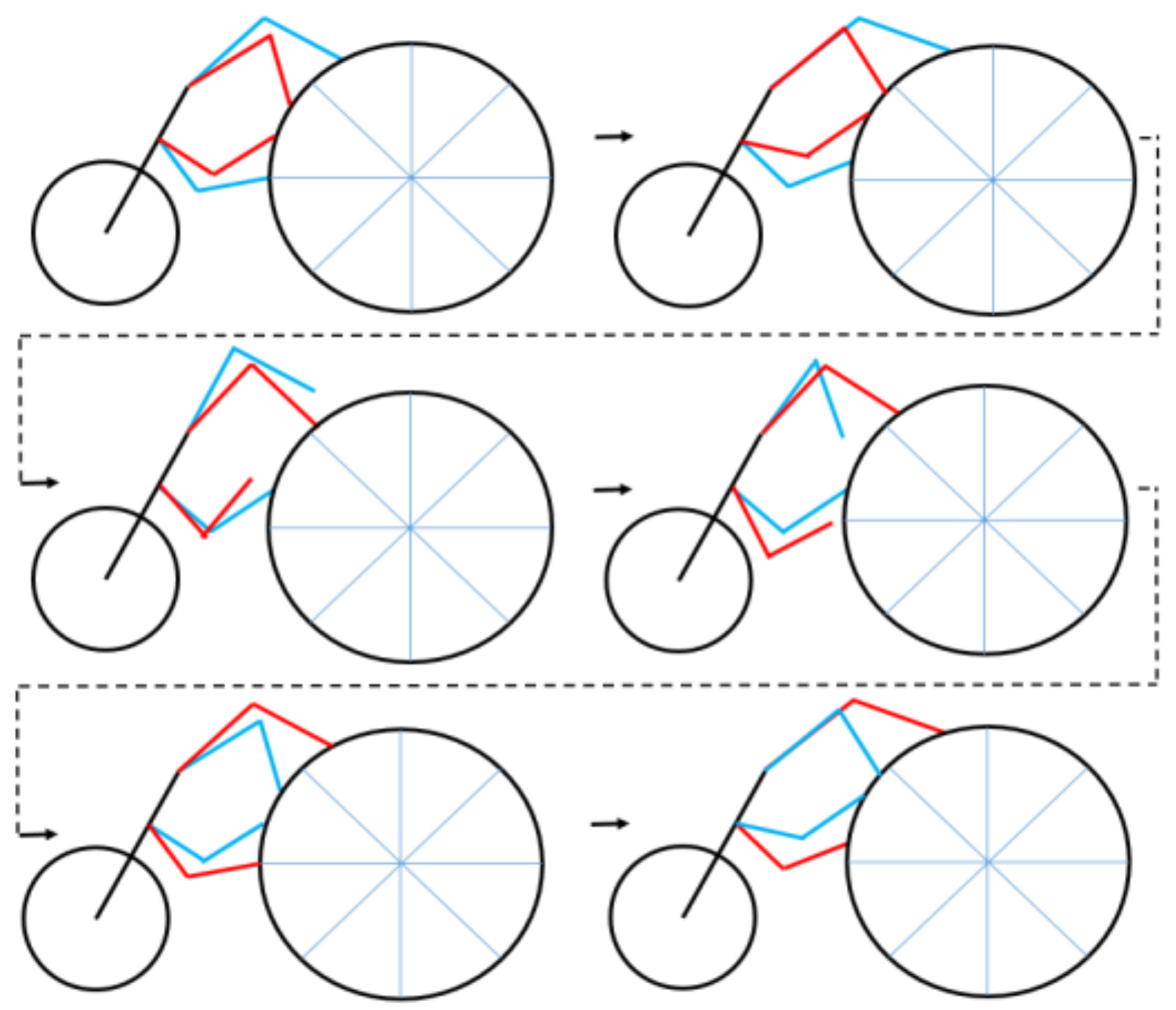
Figure 10.
The gait pattern of the robot in ball rolling motion. Red line: Legs at robot’s right side; Blue line: Legs at robot’s left side.
Figure 10.
The gait pattern of the robot in ball rolling motion. Red line: Legs at robot’s right side; Blue line: Legs at robot’s left side.

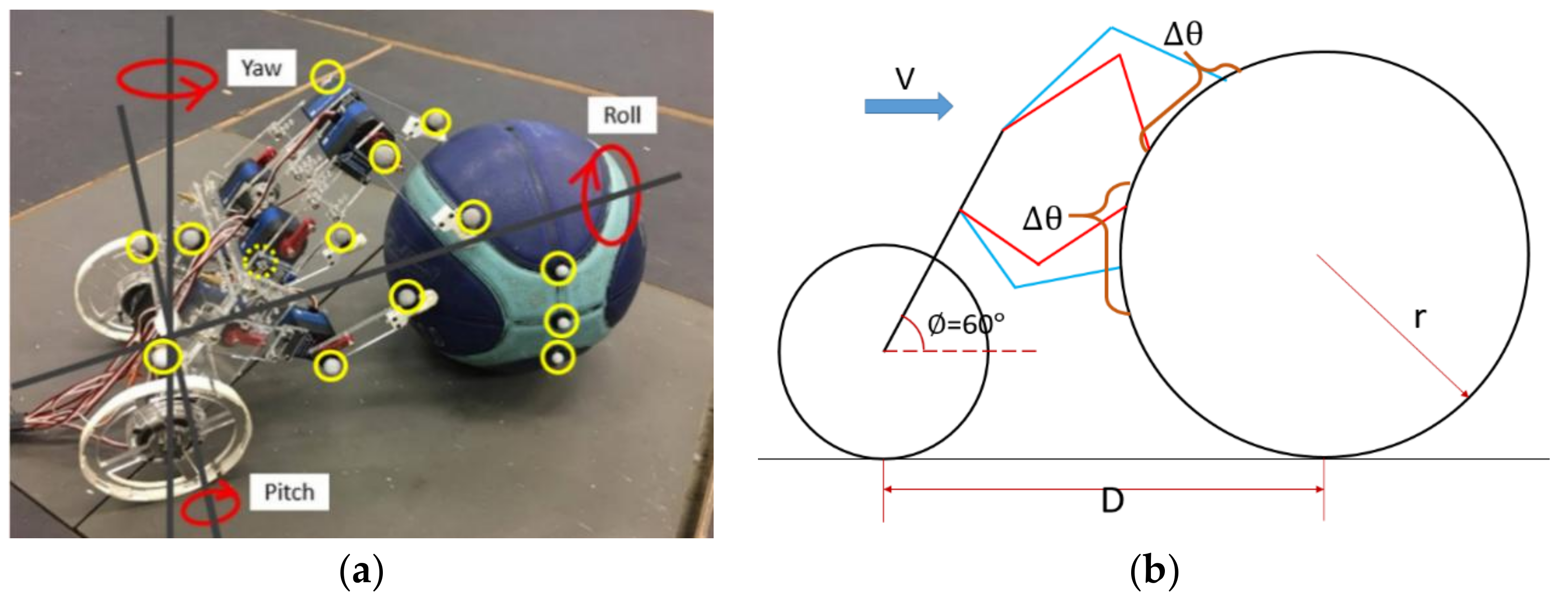
Figure 11.
(a) Markers (yellow circle) were installed on the robot and the ball to collect quantitative motion data, and (b) parameters of the robot in ball rolling motion.
Figure 11.
(a) Markers (yellow circle) were installed on the robot and the ball to collect quantitative motion data, and (b) parameters of the robot in ball rolling motion.

Figure 12.
The x-component, perpendicular to the rolling direction, of COM trajectory of the ball in each leg motion loop. The solid line indicates the average value of each time, and the error bar indicates the standard deviation of each time; (a) 40°–70° rolling range; and (b) 50°–80° rolling range.

Figure 13.
The y-component, rolling direction, of COM trajectory of the ball in each leg motion loop. The solid line indicates the average value of each time, and the error bar indicates the standard deviation of each time; (a) 40°–70° rolling range; and (b) 50°–80° rolling range.
Figure 13.
The y-component, rolling direction, of COM trajectory of the ball in each leg motion loop. The solid line indicates the average value of each time, and the error bar indicates the standard deviation of each time; (a) 40°–70° rolling range; and (b) 50°–80° rolling range.

Figure 14.
The yaw angle of the ball versus time in each leg motion loop. The solid line indicates the average value of each time, and the error bar indicates the standard deviation of each time: (a) 40°–70° rolling range; and (b) 50°–80° rolling range.
Figure 14.
The yaw angle of the ball versus time in each leg motion loop. The solid line indicates the average value of each time, and the error bar indicates the standard deviation of each time: (a) 40°–70° rolling range; and (b) 50°–80° rolling range.

Figure 15.
(a) The planar COM trajectory of the robot body viewed from above. The solid line indicates that the rolling range is from 40° to 70°, and the dashed line indicates the rolling range is from 50° to 80°. (b) The inclination of the robot body versus time. The solid line indicates that the rolling range is from 40° to 70°, and the dashed line indicates that the rolling range is from 50° to 80°.


Table 1.
Specification of the dung beetle robot.
| Specification | Detail |
|---|---|
| Size | 450 mm × 250 mm × 120 mm |
| Mass | 1500 g |
| Body material | Acrylic (PMMA, Taipei, Taiwan) |
| Leg actuator (LM, LH, RM, RH) | Servomotor (ARS-3216HTG + HV, Alturn USA, Taichung, Taiwan) |
| Leg actuator (LF, RF) | Servomotor (MG995, Tower Pro, Taipei, Taiwan) |
| Controller | myRIO, Natinoal Instruments (Austin, TX, USA) |
© 2018 by the authors. Licensee MDPI, Basel, Switzerland. This article is an open access article distributed under the terms and conditions of the Creative Commons Attribution (CC BY) license (http://creativecommons.org/licenses/by/4.0/).
Share and Cite
MDPI and ACS Style
Wang, J.-W.; Chiang, Y.-S.; Chen, J.; Hsu, H.-H. Development of a Dung Beetle Robot and Investigation of Its Dung-Rolling Behavior. Inventions 2018, 3, 22. https://doi.org/10.3390/inventions3020022
AMA Style
Wang J-W, Chiang Y-S, Chen J, Hsu H-H. Development of a Dung Beetle Robot and Investigation of Its Dung-Rolling Behavior. Inventions. 2018; 3(2):22. https://doi.org/10.3390/inventions3020022
Chicago/Turabian StyleWang, Jen-Wei, Yu-Sheng Chiang, Jhih Chen, and Hao-Hsun Hsu. 2018. "Development of a Dung Beetle Robot and Investigation of Its Dung-Rolling Behavior" Inventions 3, no. 2: 22. https://doi.org/10.3390/inventions3020022