Article

Inexpensive Piezoelectric Elements for Nozzle Contact Detection and Build Platform Leveling in FFF 3D Printers

RepRap Project, Foxham, Wiltshire SN15 4NB, UK
*
Author to whom correspondence should be addressed.
Inventions 2018, 3(1), 8; https://doi.org/10.3390/inventions3010008
Submission received: 25 November 2017 / Revised: 11 January 2018 / Accepted: 21 January 2018 / Published: 25 January 2018
(This article belongs to the Special Issue Innovations in 3-D Printing)

Abstract

:
Inexpensive piezoelectric diaphragms can be used as sensors to facilitate both nozzle height setting and build platform leveling in Fused Filament Fabrication (FFF) 3D printers. Tests simulating nozzle contact are conducted to establish the available output and an output of greater than 8 Volts found at 20 °C, a value which is readily detectable by simple electronic circuits. Tests are also conducted at a temperature of 80 °C and, despite a reduction of greater than 80% in output voltage, this is still detectable. The reliability of piezoelectric diaphragms is investigated by mechanically stressing samples over 100,000 cycles at both 20 and 80 °C, and little loss of output over the test duration is found. The development of a nozzle contact sensor using a single piezoelectric diaphragm is described.

1. Introduction

RepRap printers are low cost 3D printers which can reproduce a substantial portion of the components that were used in its own construction. The RepRap project started at the University of Bath as an initiative to develop a low-cost 3D printer and now has many hundreds of collaborators. The stated goal of the RepRap project is “to produce a pure self-replicating device not for its own sake, but rather to put in the hands of individuals anywhere on the planet, for a minimal outlay of capital, a desktop manufacturing system that would enable the individual to manufacture many of the artifacts used in everyday life” [1]. In order to meet the requirement for a minimum outlay of capital, a core objective of the RepRap project is that RepRap printers should be able to print many of the parts that are used in their own construction. Those parts of a RepRap printer that cannot be printed should be both readily available and inexpensive [2]. Although designed as sounders, piezoelectric discs will also function as sensors as they are useful components for making RepRap printers; this paper addresses the suitability of piezoelectric diaphragms as sensors for build platform leveling in Fused Filament Fabrication (FFF) printers.
Piezoelectric diaphragms are readily available as they are used as in many manufactured goods and are also inexpensive; prices for small quantities in December 2017 for branded diaphragms was £0.84 [3], while unbranded ones about £0.34 [4]. Piezoelectric discs may also be salvaged from many sources such as greetings cards and toys as well as electronic equipment such as phones.
A feature of piezoelectric discs which makes them suitable for use in RepRap printers, and possibly in similar applications, is that they are quite robust. With moderate care it is possible to drill holes through the ceramic and the diaphragm with only minor degradation of performance. Piezoelectric discs have also had the ceramic part segmented with the modified assembly used to provide mechanical scanning for a Maker built scanning tunnelling microscope [5].
Taken together, the low cost and ready availability of piezoelectric discs along with their robustness make them an excellent component for use in RepRap printers and indeed in other equipment for the Maker communities, in resource constrained locations and even for the quick construction of prototypes and proof of concept models in well funded organizations. A selection of piezoelectric discs are shown in Figure 1, including two salvaged components and one with a drilled hole.
FFF 3D printers, also known as FDM (Fused Deposition Modelling) printers [6] produce a solid object by printing layers of material one upon another on to a flat build platform. The adhesion of the first layer to the build platform depends on several factors, the thickness of the first layer being a very important one [7] as thick or thin areas can result in a print detaching from the build platform [8]. The nozzle height above the build platform determines the first layer’s thickness and can be influenced by many things, such as the build platform itself may be less flat than is needed for a good print; initial adjustment may have been effected by thermal expansion of parts of the printer while routine changes of parts such as the printer nozzle or build platform are likely to change the nozzle height and the first layer thickness. Measuring the nozzle height at a number of positions over the area of the build platform before the first layer is printed can allow manual correction or automatic optimization of the first layer or layers.
The early RepRap printers levelled the build platform manually by adjusting three or four sprung adjusting screws. As manual adjustment was laborious and may be required frequently, methods were sought to automatically check the height of the printer nozzle without resorting to tools such as feeler gauges. Once the earliest automatic methods of measuring the relative distance from the nozzle to the build platform became available, it became possible to use software to compensate for distortion of the build platform and ultimately to compensate for geometric errors in the printer itself.
The first methods used on RepRap, DIY and Maker built 3D printers for automatic build platform levelling measured the distance between the print nozzle and the build platform using a switch which could be manually, mechanically or electrically deployed. Proximity sensors have also been used including inductive, capacitative, ultrasonic and optical sensors, both industrial and purpose built. Proximity sensors are difficult to place close to the nozzle and will not measure the proximity of a point directly under the nozzle. Other sensors detect the nozzle contact coming into contact with the build platform so measuring the nozzle height as well as its horizontal position. The majority of the available information of the various sensors used for build platform levelling in RepRap printers can be found on the RepRap Wiki where a range of sensor types are described [9].
Nozzle contact sensors include electrical contact types which detect a conductive nozzle making contact with a conductive part of the build platform; force sensors which use a switch or transducer to detect the force of the nozzle coming into contact with the build platform; accelerometer sensors which detect the deceleration of the nozzle and attached parts when they make contact with the build platform and microphonic types where a mechanical vibration is transmitted from a driven transducer to a sensor through the contacting nozzle.
Examples of the range of technologies used for build platform levelling and nozzle height setting are itemized below, but this list is by no means exhaustive. Many of these were developed by hobbyists or other non-commercial groups before being adopted by manufacturers. Comparative data on the resolution and accuracy of different build platform leveling sensors has been compiled and published on the Duet3D forum [10].
  • The UP! Plus 2 3D Printer [11] uses two switches to set the level and the nozzle height. To establish the errors of tilt and flatness, a microswitch mounted to a carrier is connected to the nozzle and moved to contact with the build platform at a number of positions. As the microswitch actuator is directly below the nozzle this does not introduce any significant error in X or Y positions. To set the offset in the Z direction the microswitch carrier is removed and a second switch at the back and level with the surface of the build platform is contacted by the nozzle.
  • The Lulzbot Mini [12] and the Lulzbot TAZ 6 use an electrical contact method where four electrically conductive contacts at the corners of the build platform are probed by the conductive nozzle. The nozzle and contacts must be free of any insulating material such as plastic residue for this to work and in addition this method cannot find any errors in flatness of the surface.
  • The Prusa i3 [13] uses an inductive probe which the manufacturer refers to as a PINDA probe to find errors in tilt and flatness of the build surface and, by probing targets in the build platform, is also able to determine errors in XY orthogonality. Some manual setting is required after determining the errors as there is no absolute detection of the nozzle height.
  • The Ultimaker 3 printer [14] uses a capacitive detection method in which the electrical capacitance between the nozzle itself and the build platform is measured. The capacitance will increase as the nozzle approached the platform until the nozzle contacts the build platform at which point the measured capacitance will stop rising [15]. This method combines nozzle contact methods and proximity sensor methods and has no X, Y or Z offsets.
  • The Rostock Max V3 [16] uses an accelerometer [17] to detect the deceleration which occurs when the nozzle comes into contact with the build platform. There is no X or Y offset but the necessary contact speed is higher than other nozzle contact methods and a somewhat larger Z offset is to be expected.
  • The Fusion3 F400 printer [18] uses and infra red proximity sensor [19] to detect errors of tilt and flatness. As the sensor is mounted alongside the nozzle there will be offsets in X, Y and Z which will need to be compensated for in the printer software. Too much or too little reflectivity along with multiple reflections from the top and bottom surfaces of a transparent build platform can cause problems.
In addition to the methods used by commercial and kit printers, the RepRap, Maker and DIY community members have investigated a wide range of ways of detecting proximity or contact and a selection of these is itemized below.
  • Early microswitch probes were often deployed by small servos designed for use in radio controlled models. These probes had disadvantages such as poor repeatability and high mass although the method of moving a switch actuator to a point beyond the nozzle is used in several products intended for the DIY 3D printer builder. The BLTouch [20] is an example of a deployable switch sensor which uses a solenoid to extend the switch actuator.
  • Capacitive, Inductive and Optical proximity sensors are popular and can have good repeatability although they can be dependant on the correct build surface. A popular example of a Capacitive sensor is the Baomain LJC18A3-H-Z/BX [21], while the Hictop SN04 [22] is a frequently used Inductive Sensor.
  • An early example of nozzle contact sensors was the use of force sensitive resistors [23] placed under the build platform and these are now a common accessory for delta 3D printers [24].
  • An example of a nozzle contact sensor using the strain gauge principle is the Delta Smart Effector [25] in which the elements constituting the strain gauge are etched into the copper clad laminate of a printed circuit board.
Although there had previously been discussion in public forums of the possible use of piezoelectric diaphragms as sensors in RepRap printers, their first reported use was by Njål Brekke [26].
The piezoelectric diaphragms described in this paper are typified by the Murata 7BB series [27] and any functionally similar replacements from unidentified manufacturers. These diaphragms are used in musical novelties, as the voice in toys, to produce the warning sound in alarms, to replace the mechanical click sound in tactile keyboards, and in a great many other ways.
Conversion of electrical energy to mechanical energy in piezoelectric diaphragms is by what is correctly termed the “Inverse Piezoelectric Effect”. However, piezoelectric materials also exhibit the “Direct Piezoelectric Effect” where mechanical energy is converted to electrical energy; it is this effect which is used by the sensors described in this paper. The diaphragm consists of a piezo-active ceramic disc bonded to a metal disk and a conductive layer on the opposite surface which form the electrical connections.
The design intent of these piezoelectric diaphragms is the conversion of electrical energy to mechanical movement when an electrical potential applied to the piezo-active ceramic causes the centre of the diaphragm to bow relative to the periphery. The ceramic used will also operate in the reverse sense, a pressure that causes the diaphragm to bow or to bend will generate an electrical charge between the electrodes. In addition, a pressure applied directly between the face and the substrate without causing it to bend will also generate an electrical charge.
In order to assess the usefulness of inexpensive piezoelectric diaphragms as sensors in FFF printers an experiment has been designed and equipment constructed to simulate nozzle contact events in FFF 3D printers. Various pressures are applied directly to a piezoelectric diaphragm and the voltage generated are recorded.
It is known from earlier tests [28] that the response of piezoelectric diaphragms can be considerably reduced with increasing temperatures although it should be noted these were only records of a single pressure release event and would not be indicative of long term performance. It was however noted that some makes of piezoelectric diaphragms performed much better than others.
The limitation of use at higher temperatures is investigated in this article as well as the effect of large numbers of simulated nozzle contact events at room temperature and at temperatures near the limit of sensitivity. Data is compared for diaphragms before and after thermal cycling to assess the ageing of the diaphragms in service.
The development of a Z probe integrated into the printer hotend is described by Simon Khoury in the discussions section of this article.

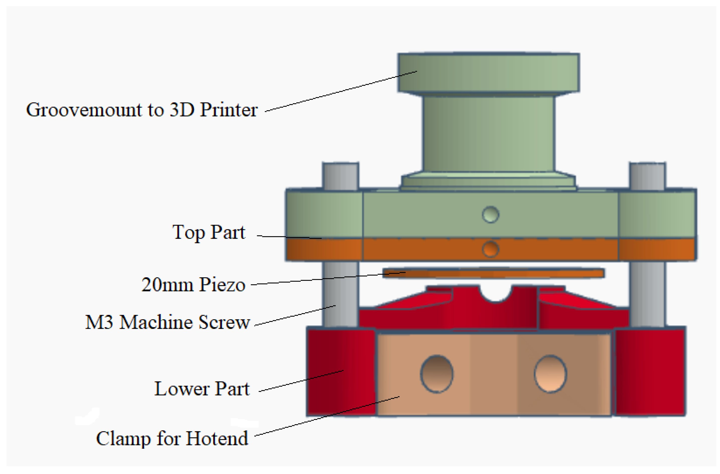
2. Materials and Methods

The experiments conducted were intended only to determine if piezoelectric discs could be used reliably as a method of detecting a contact between the printer nozzle and the printer build platform with an acceptable degree of accuracy. It was a further aim to determine if the reliability or accuracy would be adversely affected by long term use or if higher temperatures would cause a loss of reliability.
The upper and lower limits of thickness of all parts of the initial layer of plastic which will be fully adhered to the build platform can change with many factors: the thickness of the first layer, the nozzle diameter, the plastic material, linear speed of deposition, width of plastic laid down, etc. For typical RepRap FFF printers with a nozzle size between 0.25 and 0.5 mm and a first layer thickness of 0.25 to 0.3 mm, a commonly accepted variation from the desired thickness of ±50 μ m is regarded as being acceptable.
An Electrical Response jig to simulate nozzle contacts was constructed and mounted in a Proxxon MF70 light milling machine [29] modified for Computer Numerical Control (CNC) control which was controlled through Mach3 software [30] to provide the required mechanical action. The jig is depicted in Figure 2 and has a small table mounted on an actuator rod which is connected to a 3D printed parallel mechanism, the parallel mechanism transferring pressure to the piezoelectric diaphragm through a 3D printed pressure pad. A load spring maintains an upward pressure on the actuator rod and on the diaphragm through the parallel mechanism. A pre-load adjuster centres the pressure pad at its resting position and provides a small force on the piezoelectric disc after the spring load has been removed. The CNC machine is programmed to start a probe moving towards the actuator from 1 mm above it and to continue for 0.5 mm after striking the actuator. This was done to eliminate the effects of the acceleration and deceleration times which are a feature of CNC programs.
In order to check for loss of sensitivity in use including that at higher temperatures, a test rig was fabricated to stress piezoelectric discs by alternately applying a pressure to the disc and relaxing that pressure over a large number of cycles and over a range of temperatures. The rig consists of an aluminium block having a flat surface on which the piezoelectric disc is mounted and a pressure pad having a flat surface of the same diameter as the upper electrical contact of the disc. A force generated by a spring is applied by way of an actuator rod and a parallel mechanism to the pressure pad; an electrical solenoid acts to relax the major part of the pressure on the piezoelectric disc at regular intervals.
Provision is made to adjust the pressure on the pad due to the spring, the pressure due to the elasticity of the joints of the parallel mechanism and the mechanical travel of the armature and actuator rod. The rig, shown in Figure 3, is mounted on a stand which also carries a dial indicator for checking the travel of the actuator rod and the pressure pad adjusting screw during adjustment. An upward force is applied through the return spring adjusting eye with a spring dynamometer to set the spring pressure. Adjusting the pre-load applied by the parallel mechanism is done by lifting the free end of the parallel mechanism with a spring dynamometer with the solenoid operated. During commissioning of the rig the following were found to be usable values: force applied by the parallel mechanism alone to the piezoelectric disc 0.5 N; force applied through the actuating rod 4.5 N when lifted 0.25 mm from its resting position; Armature to Solenoid clearance in the non-operated state 0.8 mm; and over-travel of the actuator rod from the point that pressure is relaxed to full travel of the solenoid 0.3 mm. The dial indicator is removed during cycling tests.
The temperature of the piezoelectric disc is maintained by a resistance heater in the heater block and a thermocouple temperature controller [31]. The voltage generated by the piezoelectric disc was recorded by a digital storage oscilloscope [32] and a X10 probe.

3. Results

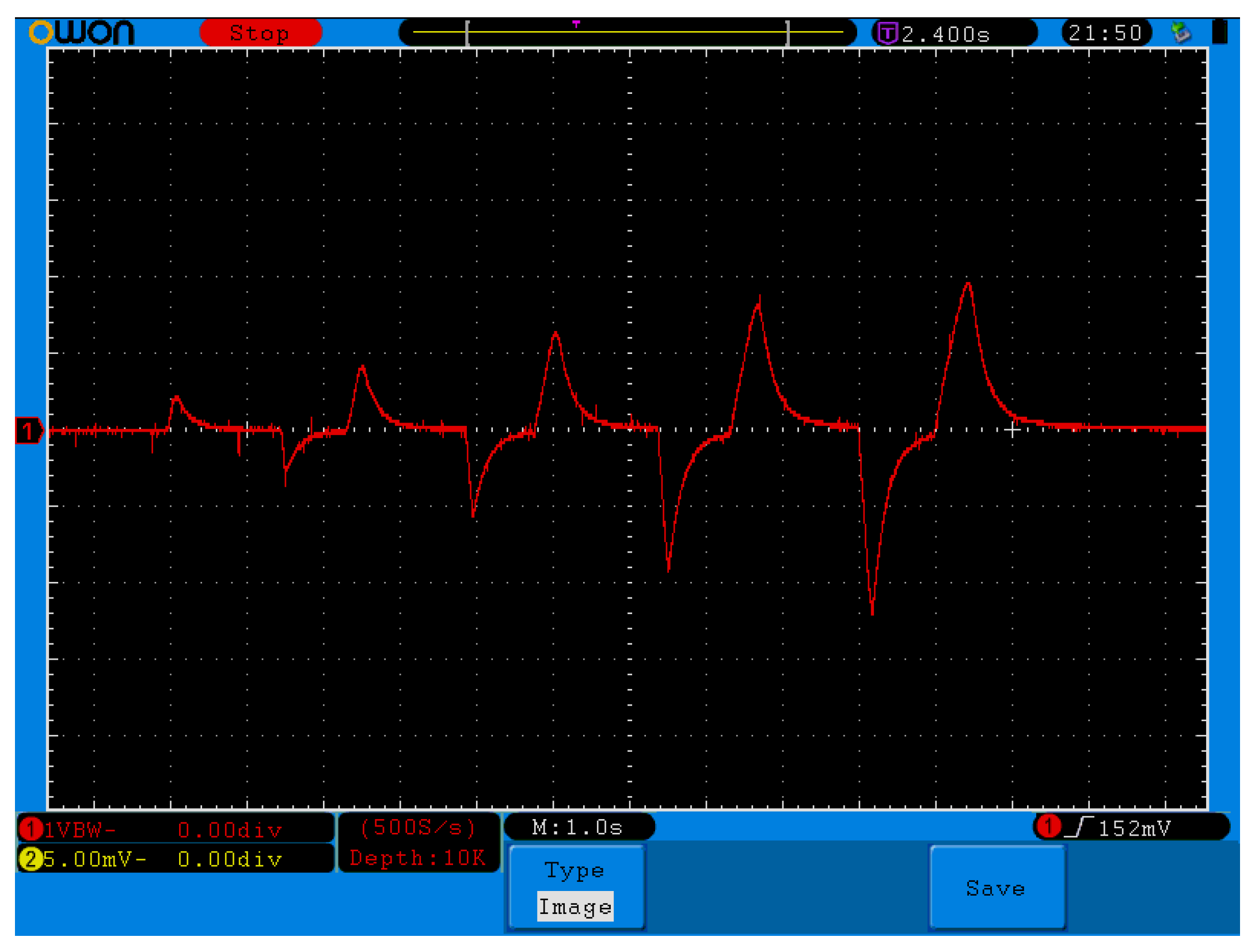
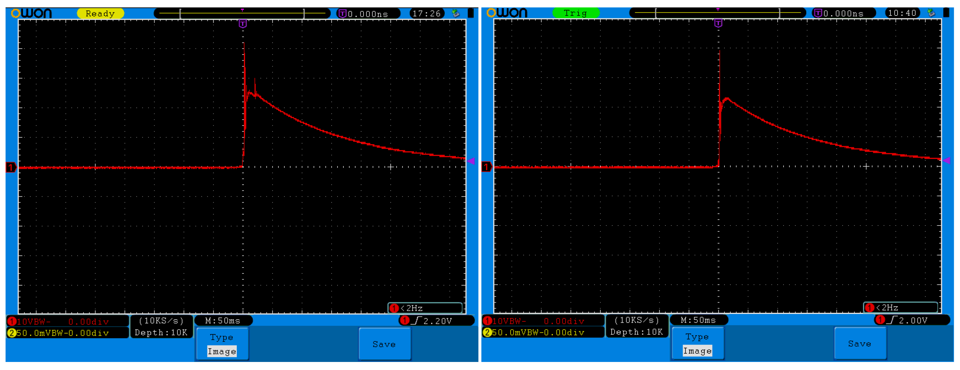
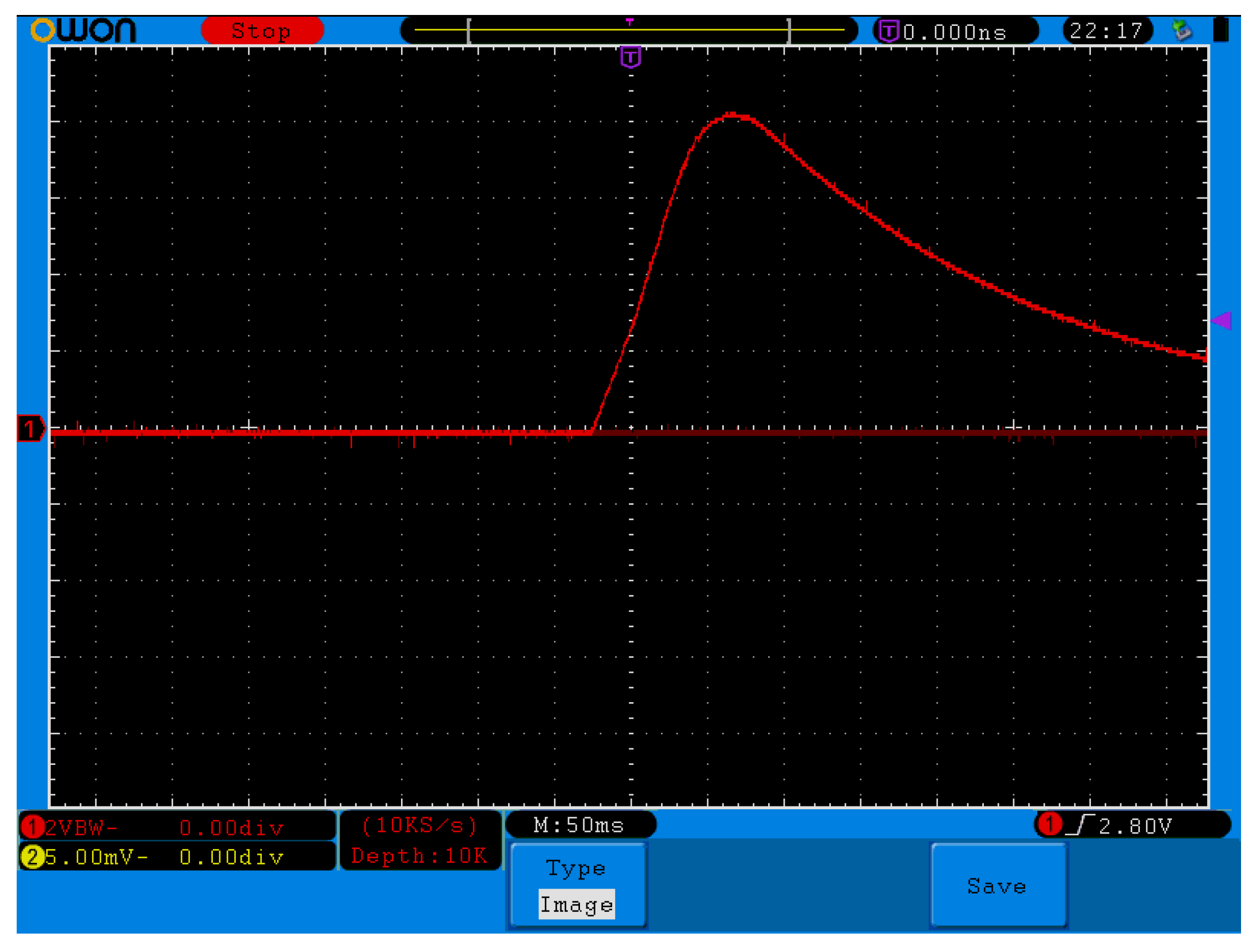
3.1. Electrical Response of Piezoelectric Diaphragms

A first batch of 10 piezoelectric diaphragms were obtained on eBay, the manufacturer of these is unknown but they were similar in size and appearance to Murata 7BB-27-4LO. The traces below were all from one of these diaphragms fitted in the Electrical Response Jig shown in Figure 2.
In Figure 4 the probe strikes the actuator at 1 mm per second and the peak voltage obtained from the piezoelectric diaphragm was 8.1 Volts which occurred 90 ms after the first contact. After initial contact there is a linear increase of voltage at 120 volts per second until the actuator rod loses contact with the parallel mechanism and the voltage across the diaphragm decays through the resistance of the oscilloscope probe. For a piezoelectric diaphragm (Murata 7BB-27-4LO) the capacitance is 20 nF ± 30%, measured with a 10 M Ω oscilloscope, the time constant τ = 200 ms which is quite close to the decay seen in Figure 4.
The probe strikes the actuator and over-travels by 20 μ m each cycle from 20 to 220 μ m. The voltage response is shown in Figure 5. The increase in peak voltage is again approximately linear. However the travel at greater than 120 μ m is 33% more than the 90 μ m implied by the first test. It is speculated that this is due to the deceleration phase from the CNC software although an exact value for this is not known.
To obtain data on the force response the solid probe was replaced with a light spring and travel was set so that with each cycle the force applied by the spring was increased by 20 g force to a maximum of 100 g force. To obtain the required spring rate an Entex stock No. 3352 spring was shortened to give a rate of 125 g per mm. The resulting voltage is shown in Figure 6, the available voltage being significantly reduced by resistive leakage through the oscilloscope probe.
The remaining nine piezoelectric diaphragms were all checked for basic voltage output and did not differ visually from the first one shown in Figure 4.

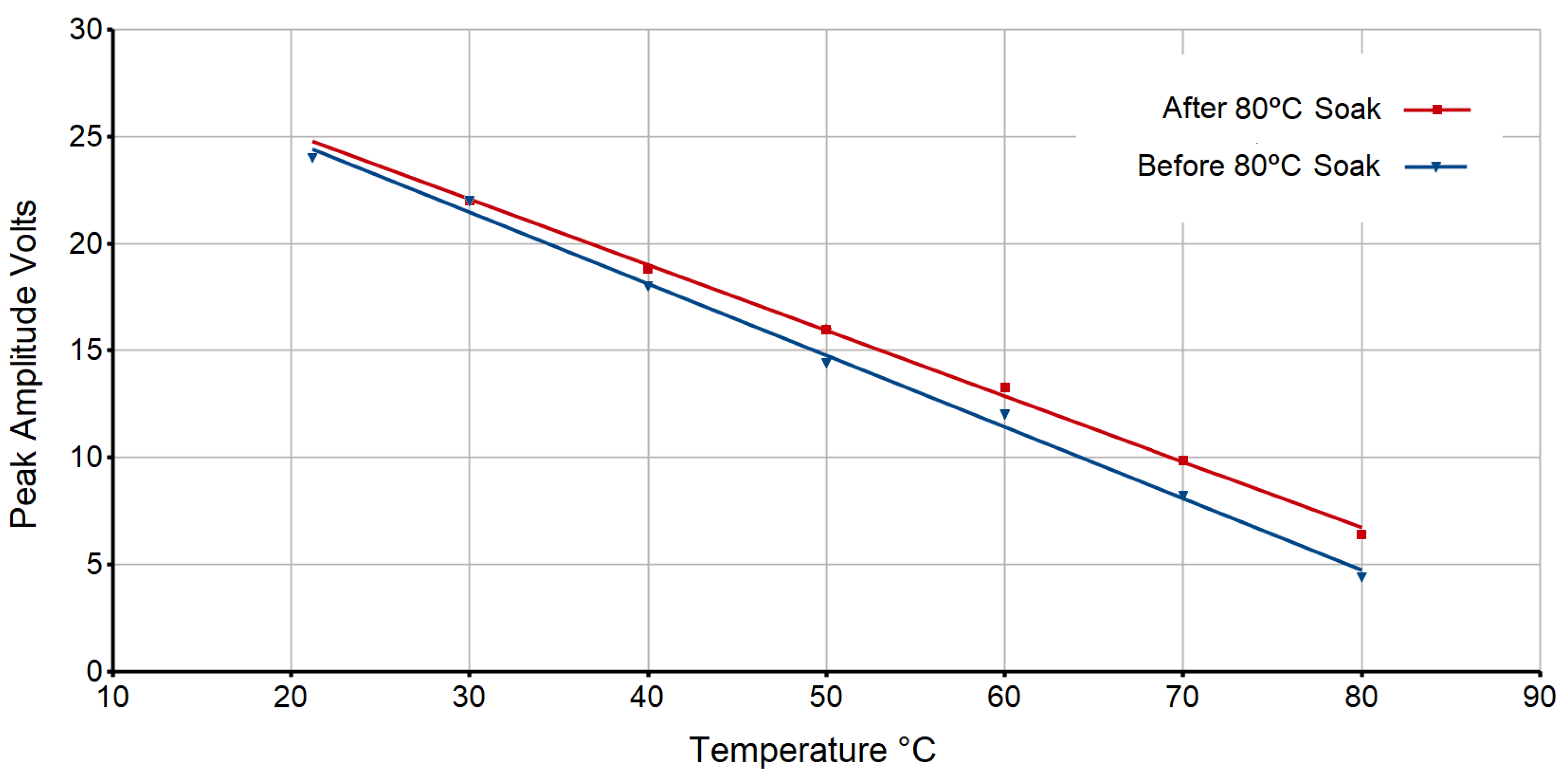
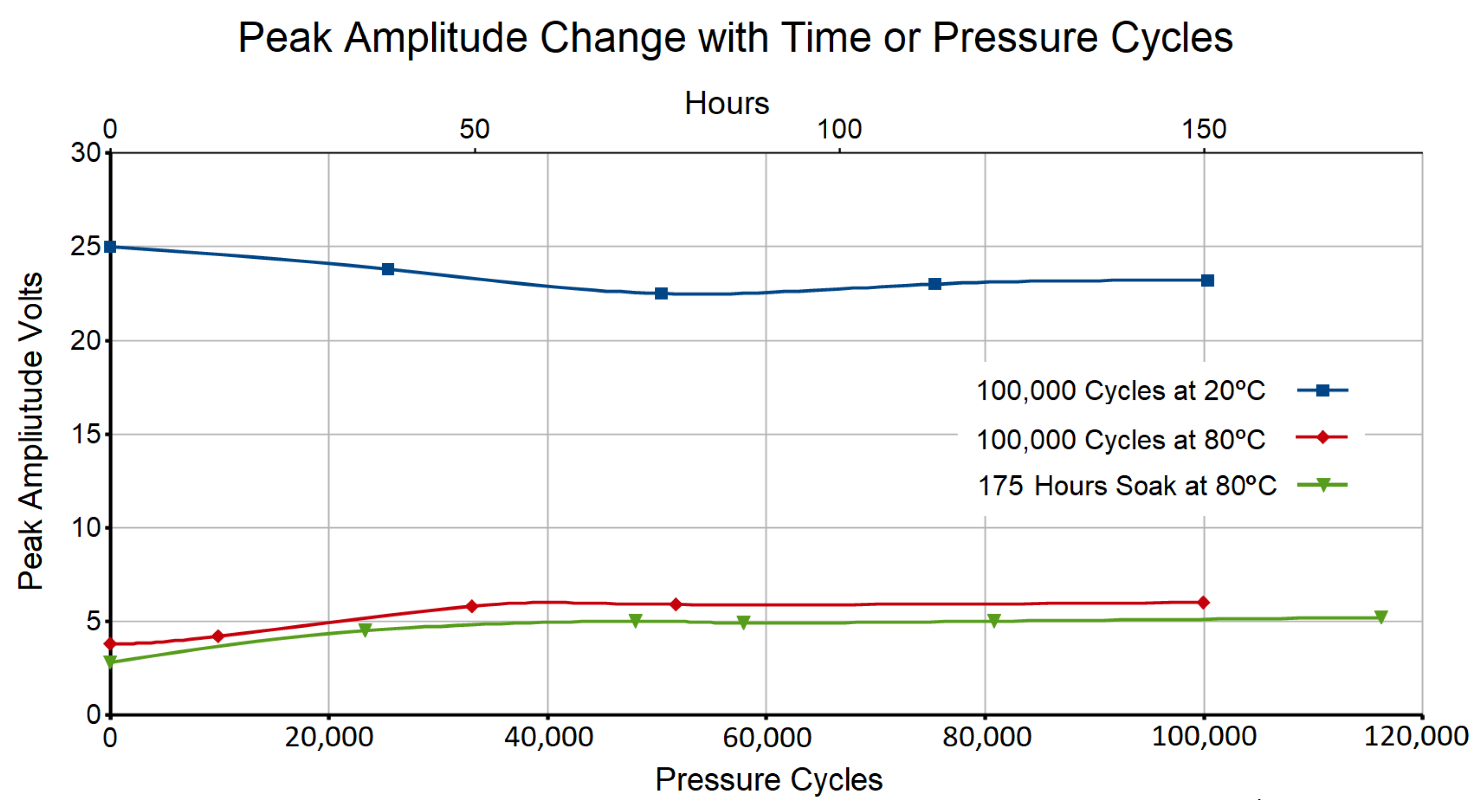
3.2. Cycling Tests to Determine Service Life

Using the test equipment shown in Figure 3, a Murata 7BB-27-4LO piezoelectric diaphragm was mounted and subjected to 100,000 cycles of pressure at 5 N relaxed every 5.4 s to 0.5 N for 2 s. After an initial hour to allow the equipment to settle the output was monitored and recorded every 25,000 cycles. The temperature was checked when each reading was taken and remained within 20 ± 2 °C at each reading. The first and final oscilloscope records are shown in Figure 7 and the peak value graphed and shown in the top (blue) trace in Figure 8. During this test the peak voltage fell from 25 to 23.2 V.
To investigate any change that may occur at higher temperatures the piezoelectric diaphragm was replaced with a new Murata unit and the temperature of the heater block raised to 50 °C. The peak amplitude was initially 12.0 V but increased to 13.5 V after 50,000 cycles. As this increase had been unexpected, a further new Murata piezoelectric diaphragm was fitted and the temperature increased to 80 °C. At this higher temperature the peak amplitude increased from 3.8 to 6.0 V over the duration of the 100,000 pressure cycles, this change being plotted in the red line in Figure 8.
To determine if the increase was an effect of the temperature alone, a further test was devised. Using a new piezoelectric diaphragm the rig temperature was rapidly bought up to 80 °C while the diaphragm was maintained at a pressure of 5 N without pressure cycling. At several points the solenoid was operated for long enough for three pressure cycles to be applied and the resulting voltage to be recorded, about 15 s. The resulting peak amplitudes, recorded over 175 h and plotted in the lower (green) trace in Figure 8, indicate that the higher temperature is the principle cause of the rise in output.
In previous tests [28] a relatively rapid decline in sensitivity of piezoelectric diaphragms with increasing temperature was found. A new test was conducted in order to better categorize this in combination with the observed increase in high temperature sensitivity over time. A new piezoelectric diaphragm was fitted to the temperature response rig Figure 2 and the pressure cycled as in earlier tests. The temperature was bought up rapidly in 10 °C steps to 80 °C and the peak amplitude at each interval was recorded. The test was continued for 50,000 cycles with the temperature held at 80 °C after which the heater was turned off and peak amplitude recorded every 10 °C down to 30 °C. The results of this test are plotted in Figure 9, the lower (blue) line showing the peak values before the heat soak and the upper (red) line showing the peak values after the soak.

4. Discussion

4.1. Piezoelectric Sensors in RepRap Printers

Since the introduction of this method of detecting nozzle contact, members of the RepRap community have used a wide range of ways of applying piezoelectric diaphragms, not only for this purpose, but also to replace limit switches used for detecting the homing position for delta printers as well as Cartesian printers. A nozzle contact technique which has been successfully applied is to use a single diaphragm in a fitting which holds the hot-end of the printer—an example of this is described below and kits are available from [33]. Piezoelectric diaphragms may be fitted to detect upward contact pressure at the nozzle end, or they may be used to sense the downward pressure on the build platform by using a number of diaphragms—typically three—mounted between the platform and its mountings.
The RepRap forum has been instrumental in the development of this technology with active threads following the development of the idea [34], support of both the open source, and purchased kits of piezoelectric Z probes as well as the development of conditioning circuitry [35,36].
The conditioning circuitry typically consists of a resistance/diode protection circuit followed by a high impedance low gain (unity to five) amplifier and a comparator. There may be low pass filtering of the input signal to remove mechanical and electrical noise and high pass filtering to remove the effect of temperature drift on the piezoelectric diaphragm. The most commonly used conditioning circuitry is that designed by Idris Nowell (Moriquendi) and is available through Precision Piezo [33].
There is some evidence that the use of piezoelectric diaphragms in Maker and DIY printers has spread beyond the immediate RepRap community with kits being sold in South America [37] and pirated copies being available from a Chinese source [38].

4.2. Piezo Electric Nozzle Contact Sensing by Use of Drilled Piezo Ceramic Discs

A further development in the use of piezoelectric sensing systems, as discussed here, was made by Simon Khoury. At the time (Jan 2017) the use of piezoelectric sensing of nozzle contact by placement of piezoelectric discs either beneath a 3D printer’s build platform, or somewhere upon its print head assembly, was already known. However, the system of placing the discs below the build platform, required at least three piezodiscs, sometimes four, so was considered more complex than necessary.
The build platform assembly is frequently mounted on a moving axis, the Y-axis in some cases (I3-type printers and their derivatives) or the Z-axis (for example corexy style printers) which results in two potential issues. Firstly, if the axis in which the piezoelectric diaphragms moves and such movement is required to bring the build platform and nozzle into contact this can, depending on the design and the quality of linear motion components, create mechanical noise which reduces the sensitivity of the apparatus. As such, the scheme of placing the sensors under the build platform is especially suitable on a delta printer, where the bed is fixed in place, but less satisfactory on other designs with moving build platforms especially in the Z-axis direction. Secondly the stability of the build platform resting on mounts containing piezoelectric diaphragms, can be affected in this scheme, resulting in a mobile build platform, which inevitably causes reduction in print quality. Mounts are either more stable though more complex and expensive to build, or less stable but often cheaper and easier to construct. It is required that as much of a 3D printer be as rigid as possible in use including the build platform and its substructure, primarily to ensure the accuracy of the printed objects, and secondarily to enable accurate probing to take place. Additionally, since 3D printers enhance the adhesion of the deposited polymer to the build platform by the use of heat, usually in the range of 55 to 115 °C, the possibility that the piezoelectric discs would heat up in use existed, which would cause undesirable changes in performance (reduced sensitivity or erratic triggering). This lead to the realisation that a simpler method of using piezoelectric discs as sensors for nozzle contact was possible.
The key innovation was to drill a hole through the centre of the piezoelectric disc in such a way that it would still function adequately afterwards. Indeed, the cutting by either spur point drill bit, utilizing moderate force and low rpm, or the use of lathe to cut the hole in the disc resulted in a hole through the upper conductor, ceramic and lower brass body of the disc of good quality. A hole of between 4.5 and 5 mm was chosen to minimize the amount of ceramic material removed, which generates the voltage during deformation, and to allow the 3D printing polymer (filament) to pass through the disc. In the case of the more common 1.75 mm diameter filament type, a PTFE (polytetrafluoroethylene) guide tube (2 mm ID, 4 mm OD) was used to surround it, which prevents undesirable flexing of the filament as it is driven into the melting chamber above the printers nozzle (hotend). In the case of a 3 mm filament no guide tube was used (as this filament is stiffer due to its larger diameter). It is noteworthy that while piezo-ring devices already exist with holes centrally located, the cost of these devices is higher than for piezoelectric discs described here and they are available only from specialist suppliers.
Having determined by test probing, and testing of various drilled piezoelectric discs on an oscilloscope, that the disc still functioned as it did when un-drilled, albeit with a reduction in voltage generated equal to the proportion of ceramic material removed, but well within the range at which detection with high sensitivity is possible, the next step was to mount the disc above the extruded polymer heater assembly.
An extruded polymer heating assembly—referred to generally as a hotend—typically consists of a metal block with an electrical heating element placed into it, a nozzle threaded into the metal block through which the polymer is extruded, and a thermistor or PT100 sensor to provide closed loop control by PID of the temperature. This is attached to an externally threaded metal tube (ceramic/polymer in some types) which is threaded into the metal block (hotend) at one end, butted tightly against the mating surface of the nozzle, and at the other end into a (typically) aluminium heat-sink (correctly known as a coldend), the purpose of which is to prevent the heat in the hotend, (often between 180 and 270 °C) from rising by conduction to the print-head which can often be made of printable polymers, such as ABS (acrylonitrile butadiene styrene), to enable parts to be printed by the machine itself. These polymers would soften at around 130 °C, and deform without the heatsink, and typically a fan with duct to pass air through it.
Construction of the sensor units shown in Figure 10 consisted initially of two 3D printed polymer (ABS) components and a piezoelectric disc (Murata 7BB 27 mm). The lower part incorporated a clamp that held the heat-sink mentioned above with its hotend attached, and which incorporated a surface on its upper aspect which contacted the piezoelectric disc. The upper part on its lower aspect incorporated a surface for contacting the piezoelectric disc, fixing holes for attachment to the lower part and some method of attachment to the print-head. As such the design, in its most basic form, is a piezoelectric disc (with the hole drilled) sandwiched between two 3D printed polymer parts—one attached to the printhead and the other to the hotend/coldend assembly. The filament can pass through the sensor assembly and piezoelectric disc due to its centrally drilled hole, and into the heat-sink, hotend and reach, ultimately, the nozzle.
When the nozzle and build platform are brought together so that contact occurs, a force is generated which is transmitted directly upwards through the assembly. The force required to register contact is only in the order of 10–15 g depending on the hardness of the printing surface on the build platform, of which many types are in common use. This force can be modified by changing the speed at which the nozzle and build platform are brought together during probing. When this occurs a voltage is generated by the piezoelectric diaphragm which can be detected an amplifier circuit.
One of the key requirements of a sensor within a mounting system for the hotend/coldend assembly is for the hotend/coldend assembly mounted using it, to be as rigid as possible. Having lateral movement of the nozzle greater than 20–30 μ m during printing is highly undesirable, and would result in low accuracy printing, especially during the deposition of external perimeters. As each layer of material is deposited its upper surface is rarely uniform enough for the nozzle not to occasionally contact it when it passes over during printing of the next layer. Vertical movement of the nozzle is also undesirable but so long as it is less then 100 μ m, its effect on the accuracy of the print is acceptable. The sensor unit’s design therefore is a compromise between having high sensitivity for nozzle contact which would be achieved by having a relatively loose assembly which allows for greater compression/flex in the piezoelectric disc, yet an unstable nozzle, and having an extremely tight assembly which would have much less sensitivity due to pre-loading of the piezoelectric disc, but exhibit greater nozzle stability.
Another aspect considered was that in the first prototype shown here, which used a 27 mm piezoelectric disc, the mechanism by which force was imparted to the piezoelectric disc was by uniform compression. Whilst this achieves reasonable sensitivity, greater sensitivity can be achieved by flexing the disc. In this version four screws were used to hold the assembly together. This allowed a reasonably firm assembly to be constructed. Another version with three screws holding the assembly together was deemed to be too flexible and polymer pins were introduced alongside the screws, the idea being that the lower part could slide on the pins, the pins acting to limit lateral movement in the assembly and attached hotend/nozzle. This was later designed-out as the unit became smaller and this lateral movement was reduced.
Later versions shown here used a flange on the uppermost aspect of the lower part which engaged the piezoelectric diaphragm just lateral to the hole drilled into it and was 8 mm internal diameter and 10 mm external diameter. The upper part of the assembly incorporated a recess, with a lip into which the piezoelectric diaphragm sits. As such when these two components are attached to one another the diaphragm is bent centrally against its upper support and placed in light pre-load. This enhances sensitivity whilst achieving much less movement laterally at the nozzle. Another change was to make the unit smaller, in order to do the size of piezoelectric disc reduced from 27 to 20 mm.

5. Conclusions

The results of the equipment tests have been limited to determining if the output was sufficient even without conditioning circuitry to be reliably detected with either an analogue or digital input of an controller, typically an Arduino, such as is often used with RepRap printers. The tests did demonstrate that a useful level of reliability, sensitivity and repeatability of piezoelectric diaphragms can be expected and the cyclic tests have indicated that a long service life should also be expected. The tests conducted at 80 °C, both with pressure cycling and statically, do not extend to a long term but the relatively small change in output over the short term gives no reason to expect unreliability.
Piezoelectric diaphragms have other useful characteristics such as robustness, high availability and low cost. Some weaknesses such as the variability of response, temperature drift and polarization are known and are largely due to the uses described here relying on parameters not specified for manufacturing. Despite the foregoing, the output from these components is so large that even a poor quality piezoelectric diaphragm is able to give an output much greater than is needed for accurate detection of the 3D printer build surface.
In order to promote the widespread adoption of this technology and method of probing the build platform of a 3D printer, the company Precision Piezo [33] has been formed which has, during its first six months of operation sold some 125 units. These have been performing extremely well and the variety of 3D printers on which they are used increases daily. The technology which is discussed here is open source in nature and rooted in the RepRap community where ideas such as this continue to be discussed, developed and shared for the good of all.

Acknowledgments

This work is unfunded, the participants having covered their own material and equipment costs. Where monetary transfer between participants has been needed or where items have been sold the income has been limited to not more than the costs. MDPI has waived the Article Processing Charge. All information required to construct piezoelectric systems described in this article are open source and no patents are held nor copyrights enforced.

Author Contributions

Michael Simpson designed the experiments to investigate electrical response and service life of piezoelectric diaphragms; Simon Khoury designed several practical implementations of Z probes using piezoelectric diaphragms and maintains them in the public domain.

Conflicts of Interest

Michael Simpson declares no conflict of interest: Simon Khoury declares that he has a financial interest and is trading as “Precision Piezo”.

Abbreviations

FFFFused Filament Fabrication (equivalent to FDM)
FDMFused Deposition Modelling (term is protected by Stratasys Inc.)
ABSAcrylonitrile Butadiene Styrene

References

  1. All3DP. The Official History of the RepRap Project. 2016. Available online: https://all3dp.com/history-of-the-reprap-project/ (accessed on 17 December 2017).
  2. Jones, R.; Haufe, P.; Sells, E.; Iravani, P.; Olliver, V.; Palmer, C.; Bowyer, A. Reprap—The replicating rapid prototype. Robotica 2011, 29, 177–191. [Google Scholar] [CrossRef]
  3. RS Online Catalogue. Available online: https://uk.rs-online.com/web/p/piezo-buzzer-components/8712001/ (accessed on 10 December 2017).
  4. Rapidonline Catalogue. Available online: https://www.rapidonline.com/rvfm-ft-20t-6a1-uncased-piezo-transducer-35-0200 (accessed on 10 December 2017).
  5. Matt Freund. Cheap-Diy-Microscope-Sees-Individual-Atoms, Hackaday. Available online: https://hackaday.com/2015/01/13/cheap-diy-microscope-sees-individual-atoms/ (accessed on 10 December 2017).
  6. Griffey, J. The Types of 3-D Printing, Library Technology Reports. 2014. Available online: https://journals.ala.org/index.php/ltr/article/view/4796/5747 (accessed on 17 December 2017).
  7. Volpato, N.; Aguiomar Foggiatto, J.; Coradini Schwarz, D. The influence of support base on FDM accuracy in Z. Rapid Prototyp. J. 2014, 20, 182–191. [Google Scholar] [CrossRef]
  8. Steuben, J.; Van Bossuyt, D.; Turner, C. Design for fused filament fabrication additive manufacturing. In Proceedings of the ASME 2015 International Design Engineering Technical Conferences and Computers and Information in Engineering Conference, American Society of Mechanical Engineers, Boston, MA, USA, 2–5 August 2015. [Google Scholar]
  9. RepRapWiki Contributors. Available online: http://reprap.org/wiki/Z_probe (accessed on 17 December 2017).
  10. Duet3D Forum Page. Available online: https://www.duet3d.com/forum/thread.php?id=1330 (accessed on 10 December 2017).
  11. 3D Printing Systems. UP PLUS 2 Users Manual 2013. Available online: http://3dprintingsystems.com/UP%20Plus%202%203D%20Printer%20Manual.pdf (accessed on 8 January 2018).
  12. Aleph Objects Inc. Lulzbot Mini Users Manual. 2015. Available online: https://download.lulzbot.com/Mini/1.0/documentation/manual/LulzBot_Mini_manual.pdf (accessed on 9 January 2018).
  13. Prusa Research. 3D Printing Handbook. 2017. Available online: https://www.prusa3d.com/downloads/manual/prusa3d_manual_mk3_en.pdf?4 (accessed on 9 January 2018).
  14. Ultimaker. Ultimaker 3 Installation and User Manual. 2016. Available online: https://ultimaker.com/download/61355/Ultimaker (accessed on 9 January 2018).
  15. Inside the Ultimaker 3—Day 6—Active leveling. Available online: https://community.ultimaker.com/topic/15687-inside-the-ultimaker-3-day-6-active-leveling/ (accessed on 8 January 2018).
  16. Rostock Max. Available online: https://www.seemecnc.com/collections/3d-printers/products/rostock-max-v3-desktop-3d-printer-diy-kit (accessed on 9 January 2018).
  17. Accelerometer Sensor. Available online: https://www.seemecnc.com/products/hotend-accelerometer-probe-pcb-board-rev-5c (accessed on 9 January 2018).
  18. Fusion3. Fusion 3 F400 Users Manual. Available online: https://www.fusion3design.com/wp-content/uploads/2017/11/F400-User-Manual-Rev-16-11-9-17.pdf (accessed on 8 January 2018).
  19. F400 (Bed Leveling) Z Probe. Available online: https://store.fusion3design.com/collections/f400-s-replacement-parts/products/f400-bed-leveling-z-probe (accessed on 8 January 2018).
  20. BLTouch. Available online: https://www.antclabs.com/bltouch (accessed on 10 January 2018).
  21. Capacitive Sensor. Baomain LJC18A3-H-Z/BX. Available online: https://www.amazon.co.uk/Baomain-LJC18A3-H-Z-1-10mm-Capacitance-Proximity/dp/B015PCW2R6 (accessed on 9 January 2018).
  22. Hictop Inductive Sensor. Available online: https://www.hic3dprinter.com/products/hictop-3d-printer-self-leveling-upgrade-auto-leveling-sensor-bed-self-adjustment-inductive-proximity-sensor (accessed on 9 January 2018).
  23. Force Sensing Resistors Make for Auto Bed Levelling for 3D Printers, 3D Printing Industry. 2014. Available online: https://3dprintingindustry.com/news/force-sensing-resistors-make-auto-bed-levelling-3d-printers-24533/ (accessed on 18 December 2017).
  24. FSR Kit. Available online: https://www.ultibots.com/fsr-kit/ (accessed on 18 December 2017).
  25. Delta Smart Effector. Available online: https://www.duet3d.com/DeltaSmartEffector (accessed on 10 January 2018).
  26. Leggett, C. Norwegian Physicist Uses Piezo Discs to Add Auto Bed Leveling to His 3D Printer. Available online: https://3dprint.com/84479/piezo-3d-print-leveling/ (accessed on 29 July 2017).
  27. Piezoelectric Sound Components P37E.pdf. 2017. Available online: http://www.murata.com/~/media/webrenewal/support/library/catalog/products/sound/p37e.ashx (accessed on 2 October 2017).
  28. Entry in RepRap Forum Discussion. Available online: http://forums.reprap.org/read.php?1,635075,655510#msg-655510 (accessed on 2 October 2017).
  29. Proxxon MF70 Light Milling Machine Users Manual. Available online: http://pdf.lowes.com/operatingguides/4645489_oper.pdf (accessed on 1 October 2017).
  30. Mach3 Software Version R3.043.066. Available online: http://www.machsupport.com/software/mach3/ (accessed on 1 October 2017).
  31. Operating Manual CAL3300. 1997. Available online: http://www.advindsys.com/Manuals/CALManuals/Cal3300.pdf (accessed on 1 October 2017).
  32. User Manual Portable LCD Digital Storage Oscilloscope. Available online: http://owon.co.uk/wsb4318264101/down/PDS%20Series%20USER_MANUAL%20for%20UK%$20users.pdf (accessed on 2 October 2017).
  33. Precision Piezo Website. Available online: https://www.precisionpiezo.co.uk/shop (accessed on 18 December 2017).
  34. RepRap General Forum Piezoelectric Disks for Z Contact Detect and Bed Levelling. Available online: http://forums.reprap.org/read.php?1,635075 (accessed on 18 December 2017).
  35. RepRap General Forum Precision Piezo Z-probe Now available. Available online: http://forums.reprap.org/read.php?1,767998 (accessed on 18 December 2017).
  36. RepRap General Forum “Precision Piezo Bounty”. Available online: http://forums.reprap.org/read.php?1,787755 (accessed on 18 December 2017).
  37. Z-Probe Sensor Auto Nivelamento Impressora 3D Hotend E3d V6. Available online: https://produto.mercadolivre.com.br/MLB-857051279-z-probe-sensor-auto-nivelamento-impressora-3d-hotend-e3d-v6-_JM (accessed on 18 December 2017).
  38. Trianglelab Precision Piezo Z-Probe Universal Kit. Available online: https://www.aliexpress.com/store/product/trianglelab-Precision-Piezo-Z-probe-Universal-Kit-Z-probe-for-3D-printers-revolutionary-auto-bed-leveling/1654223_32832426899.html?spm=2114.12010615.0.0.48d9e4c57rbLvu (accessed on 18 December 2017).
Figure 1. A selection of piezoelectric diaphragms, from left to right—35 mm diameter, 27 mm with drilled hole, 20 mm diameter salvaged unit from greeting card on top, Murata unit below, 12 mm salvaged unit on right.
Inventions 03 00008 g001
Figure 2. Test equipment for obtaining response data.
Inventions 03 00008 g002
Figure 3. Test equipment for obtaining temperature response and ageing data.
Inventions 03 00008 g003
Figure 4. Z travel 1 mm per second with pre-travel and after-travel. Vertical 2 V per cm, Horizontal 50 ms per cm.
Inventions 03 00008 g004
Figure 5. Cycling 1 mm per second with increasing travel. Vertical 5 V per cm, Horizontal 1 s per cm.
Inventions 03 00008 g005
Figure 6. Cycling 2 mm per second with increasing force. Vertical 1 V per cm, Horizontal 1 s per cm.
Inventions 03 00008 g006
Figure 7. Peak amplitude after 1 h (642 cycles) and after 100,000 cycles. Vertical 10 V per cm, Horizontal 50 ms per cm.
Inventions 03 00008 g007
Figure 8. Change of peak amplitude with temperature and number of pressure cycles.
Inventions 03 00008 g008
Figure 9. Effect of temperature on peak response before and after 50,000 pressure cycles at 80 °C.
Inventions 03 00008 g009
Figure 10. Piezo Z Probe.
Inventions 03 00008 g010

