A Remote Controlled Robotic Arm That Reads Barcodes and Handles Products

Department of Mechanical Engineering, National Kaohsiung University of Science and Technology, Kaohsiung 80778, Taiwan
*
Author to whom correspondence should be addressed.
Inventions 2018, 3(1), 17; https://doi.org/10.3390/inventions3010017
Submission received: 5 February 2018
/
Revised: 23 February 2018
/
Accepted: 8 March 2018
/
Published: 12 March 2018
(This article belongs to the Special Issue Selected Papers from ICI2017 and Spintech Thesis Awards)
Abstract
:In this study, a 6-axis robotic arm, which was controlled by an embedded Raspberry Pi with onboard WiFi, was developed and fabricated. A mobile application (APP), designed for the purpose, was used to operate and monitor a robotic arm by means of a WiFi connection. A computer vision was used to read common one-dimensional barcode (EAN code) for the handling and identification of products such as milk tea drinks, sodas and biscuits. The gripper on the end of the arm could sense the clamping force and allowed real-time control of the amount of force used to hold and handle the products. The packages were all made of different material and this control allowed them to be handled without danger of damage or deformation. The maximum handling torque used was ~1.08 Nm and the mechanical design allowed the force of the gripper to be uniformly applied to the sensor to ensure accurate measurement of the force.
1. Introduction
Nowadays, robotic arms are often used to perform complex or highly repetitive tasks. The use of a robot eliminates the kind of mistakes that a weary person would make after doing a boring and tiresome task for a long time. Advances in technology have made it possible for devices with a wide range of different kinds of sensors to be devised and these are evident everywhere in our living environment [1,2]. Computer vision, using small video cameras, can identify and control motion in a robotic arm. It is only necessary for settings and parameters to be set for a robot to automatically carry out tasks such as the classification and picking and placing of objects [3,4].
Supermarkets and large retail stores face many challenges: shortages, incorrect placement on shelves and theft. Fierce market competition has led to a decline in profits and high labor costs make it difficult to ensure that there is enough staff to handle all the work in a store [5,6]. Walgreens, for example, has more than 8200 stores in the United States and they sell many tens of thousands of products every day and even the counting of so many items takes staff many hours to complete [7,8]. In 2016, Zhang et al. [9] designed a mobile robot that can automatically move along a preset path, has a radio-frequency-identification (RFID) scanner, and can carry out an inventory and scan and tag products while it is moving. In 2015, the Simbe Robotics Company developed a new robot that moves continuously along shelves to check the contents. When a problem is found, a message is sent automatically to staff for action to be taken [8,10].
The aim of this study was the development of a robotic arm with computer vision identification, as well as a mobile application (APP) for the barcode identification of goods using a WiFi connection [11,12]. The devised system could be installed on a vehicle that moves around the store to scan the bar codes of goods on the shelves. It can notify staff of the need for goods replenishment and can move products that have been incorrectly placed [13,14]. Traditional vision identification applications usually involve the use of a PC and a considerable amount of power and complicated software. However, the small computers now available are powerful, use very little power and the software needed is simple and versatile. The use of these little devices is economical and they can easily be used for such applications as goods inventory [15,16].
2. Methods and Design
2.1. The Design of a 6-Axis Robotic Arm
The 6-axis robotic arm designed and fabricated for this study is shown in Figure 1. The design is modular and each rotating joint is realized using a single joint component that is rotated by a small AX-12A servomotor unit from Dynamixel (Lake Forest, CA, USA). The solid frame and joint parts were fabricated by 3D printing using a polylactide (PLA) polymer. The parts are assembled using small screws and nuts, which makes changes to the structure very easy. The joint elements and motors can be easily exchanged.
2.2. Mechanical Design of the Gripper
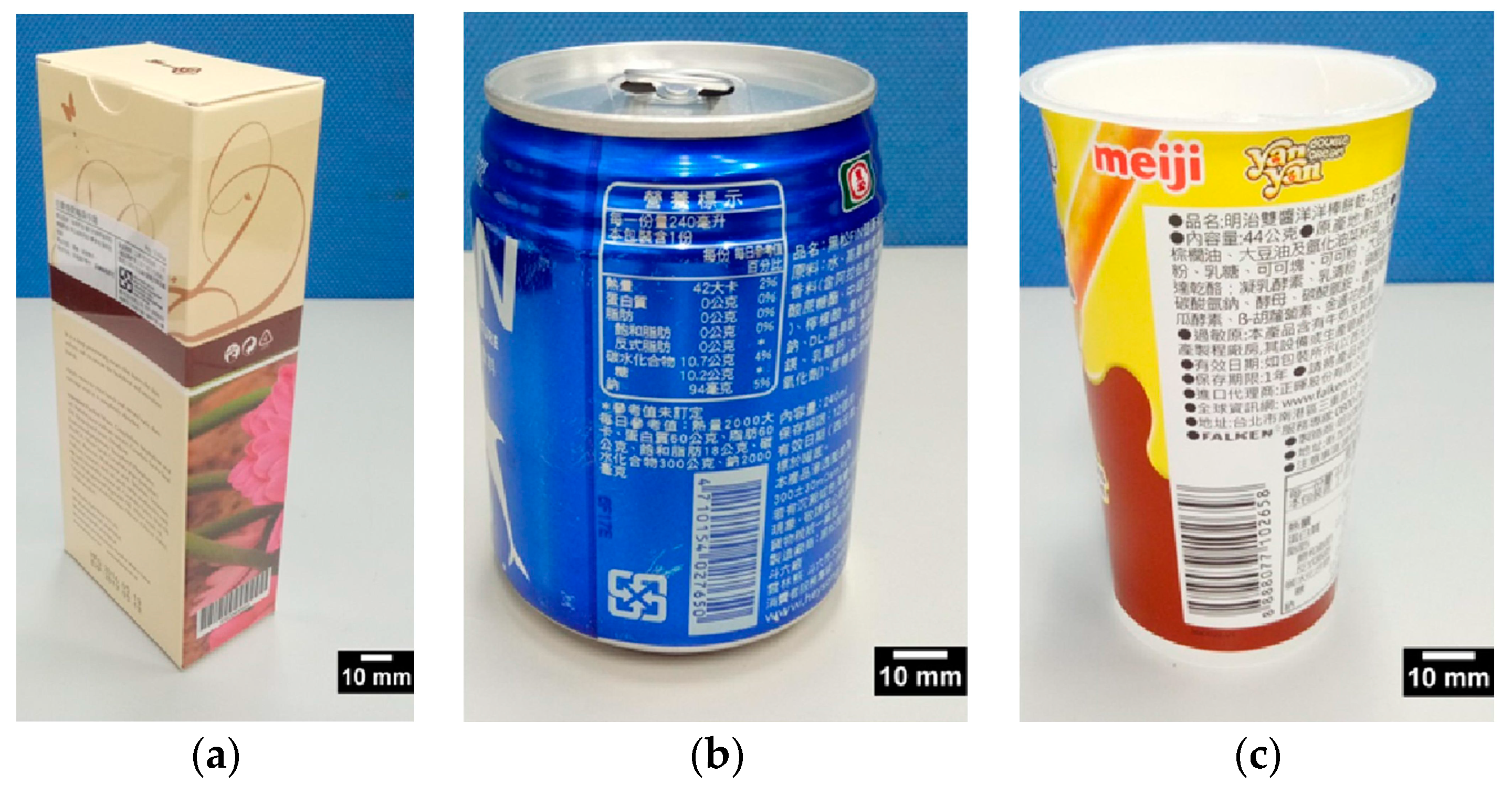
In this study we picked and placed several common packaged products. These included some made of paper, a regular aluminum can and a plastic biscuit container, see Figure 2. Their size and shape varied from 59 × 35 × 145 mm (paper package), to 66 dia × 91 mm long (aluminum can), to a 65 dia × 100 mm (biscuit package).
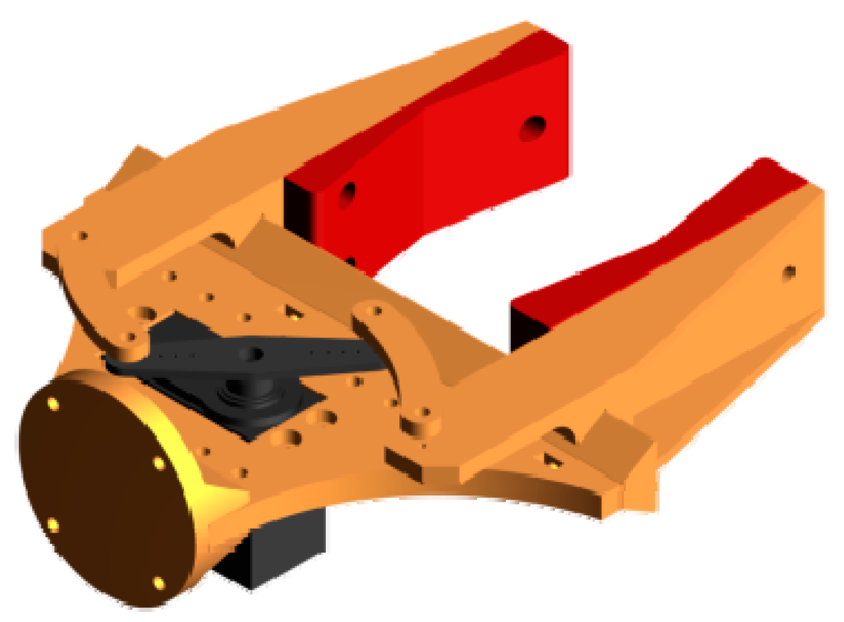
We designed a gripper for the robotic arm with a total length of 165 mm and a maximum moving distance of 97 mm, to cope with the different shapes and nature of the packages, see Figure 3. The actuator used for the sliding motion of the two gripper fingers was a TowerProMG996R servo motor unit produced by Tower Pro Ltd. (Taipei, Taiwan) (www.towerpro.com.tw), which can generate a maximum torque of ~1.08 Nm at an operating speed of 0.14 s/60° and a voltage of 6 V.
Since the three test objects were quite different in nature, one being quite strong and the other two more fragile and subject to crushing. The force exerted by the gripper jaws needed to be adjustable. The one of most common means used for gripper actuation is compressed air [17]. However, the accurate control of air pressure actuation is not easy to achieve and the irregular objects gripped can easily be crushed by either precision or power prehensile grippers [18,19]. In order to cope with this issue, the gripper we used with a precision servo motor was fitted with two force sensors of FlexiForce A301 produced by Tekscan Inc. (Boston, MA, USA) (www.tekscan.com).
2.3. Kinematics
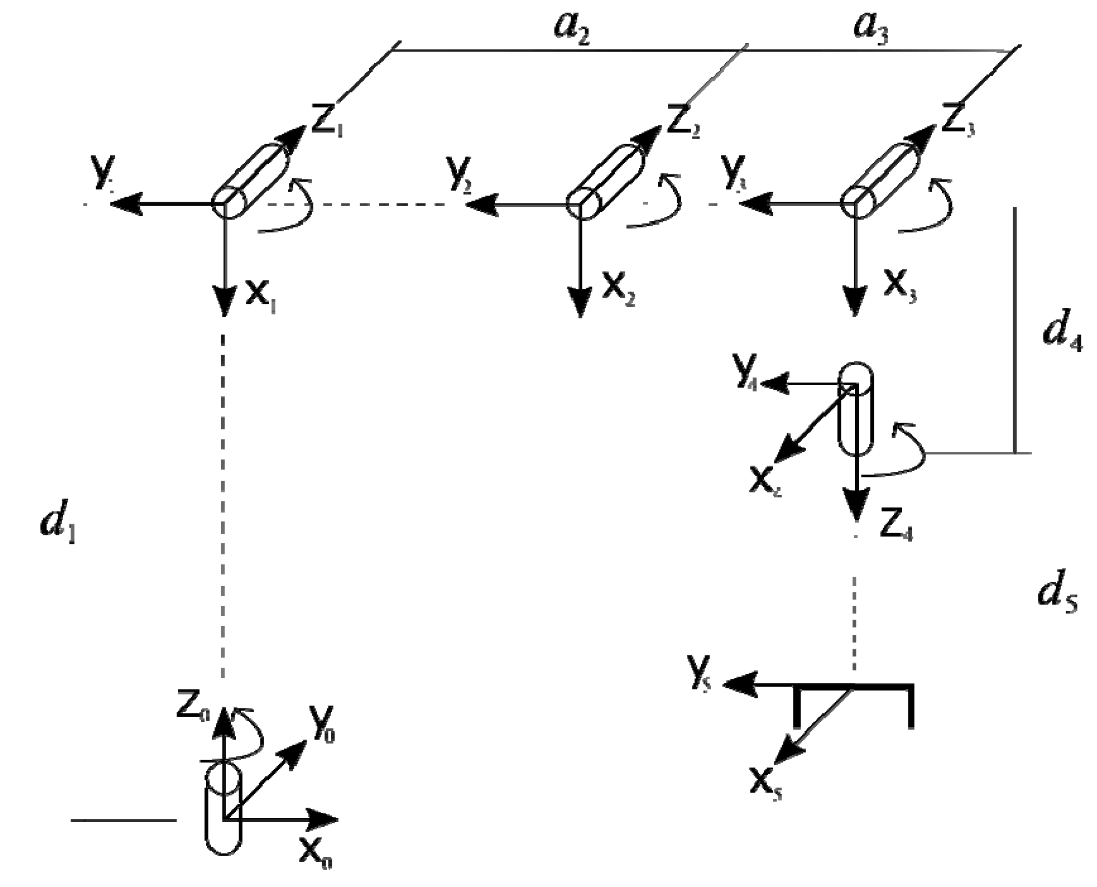
The forward and inverse kinematics of the robotic arm were physically modeled and numerically solved by Denavit-Hartenberg (D-H) matrix [20] based on the Equations (1) and (2). The robot coordinate frames for transformation are shown in Figure 4, and the corresponding D-H parameter of the robotic arm can be obtained in accordance with this model of coordinate frames.
Table 1 shows the physical parameters of the model that were substituted into the D-H matrix based on Equation (1). This yields a 0~5 axis rotation matrix. Using Equation (2), the rotation matrix of each axis was multiplied to obtain all of the elements of the matrix, as expressed in Equations (3) to (14), where è234 = è2 + è3 + è4. With Px, Py, and Pz as expressed by Equations (12) to (14), they were used to convert the angles to the coordinate system, where è23 = è2 + è3.
The inverse kinematics of the robotic arm, which could be derived from Equation (2), are related to derivation of the forward kinematics as mentioned above. The position of each linkage joint could be obtained by multiplying the matrix of each joint linkage. Therefore, after Equation (2) has been applied, we multiplied both sides of the equation by (0A1)−1, (0A1·1A2)−1, (0A1·1A2·2A3)−1, and (0A1·1A2·2A3·3A4)−1, Equations (15) to (30) will eventually be yielded, where s23 = sin(è23), s123 = sin(è123), c23 = cos(è23), and c123 = cos(è123).
3. Results and Discussion
3.1. Robotic Control
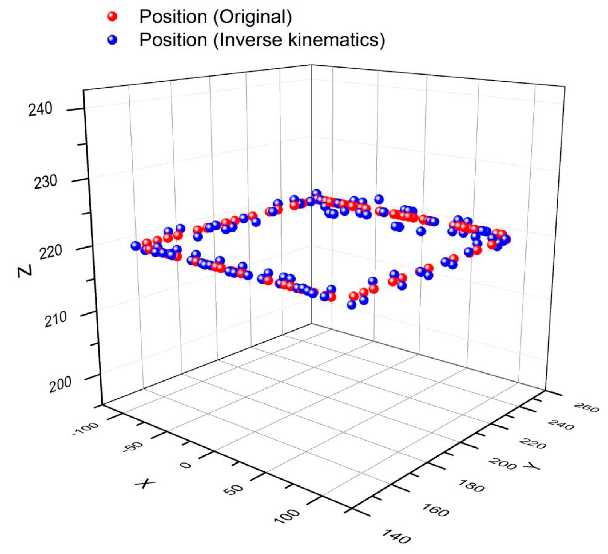
In this study, a simple graphical interface program was designed for the numerical simulation of motion of the robot arm, as shown in Figure 5. The motion of the robotic arm could be simulated by entering the coordinate points of the end actuator or the rotation angle of each axis joint. Furthermore, the end actuator of the robot arm (without the pick-up of any one object) was simulated to move along rectangular coordinates X (−100~100), Y (150~250) and Z fixed to 220. The calculated and measured results of the rectangular motion of the robotic arm are shown in Figure 6.
It should be noted that the actual position was determined using the position encoder of the servo motor as the robotic arm moved over time. The angles measured using the encoders were compared to the theoretical angles from the simulation calculation, where the angle of each axis was converted to the corresponding actuator coordinates using forward kinematics, as mentioned earlier. The aim was to verify that the forward kinematics and inverse kinematics were correctly presented in the study.
In Figure 6, the solid red line represents the planned path from the numerical calculation by the computer program, while the solid blue circular dots stand for the measured coordinates of the robot arm end actuator in actual motion. The average errors of the tri-axial coordinates were determined as X = 2.49%, Y = 0.14%, and Z = 0.28%.
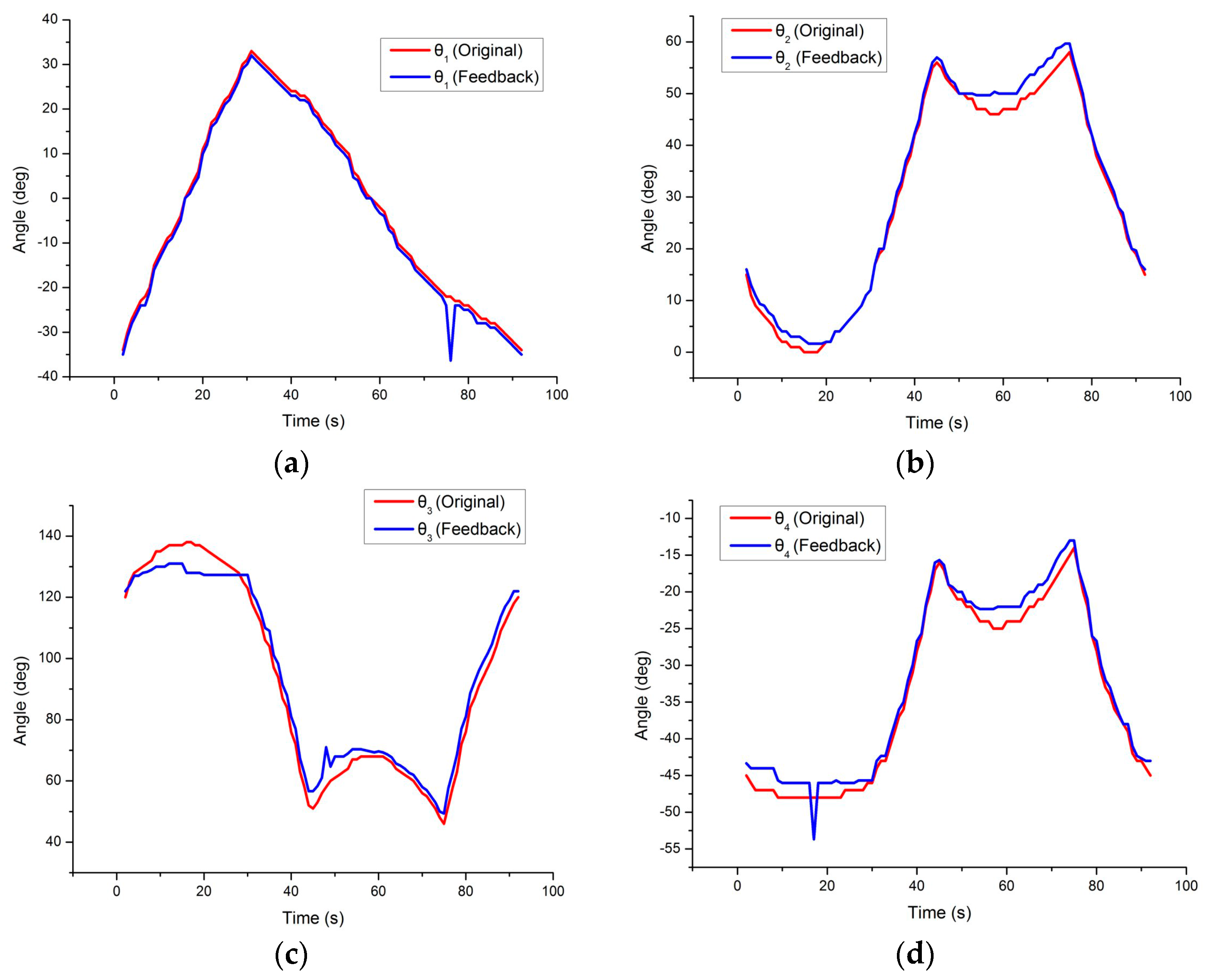
Similarly, the simulated and measured results of axis angles for all the servo motors are shown in Figure 7. It can be found that the angle deviation of the third axis is more severe than that of the other axes because the third axis is influenced by the weight of the robotic arm under the load of the servo motor. The average angle errors are 11.11% for the 0-th axis, 14.39% for first axis, 4.85% for the second axis, and 4.90% for the third axis. Tests were also carried out with the gripper carrying an object over the same path. The simulated and measured results are shown in Figure 8. It can be seen that the position of the end-actuator offset path was increased when an object was being carried by the gripper. The average tri-axial coordinates errors are X = 2.49%, Y = 0.14%, and Z = 0.28%.
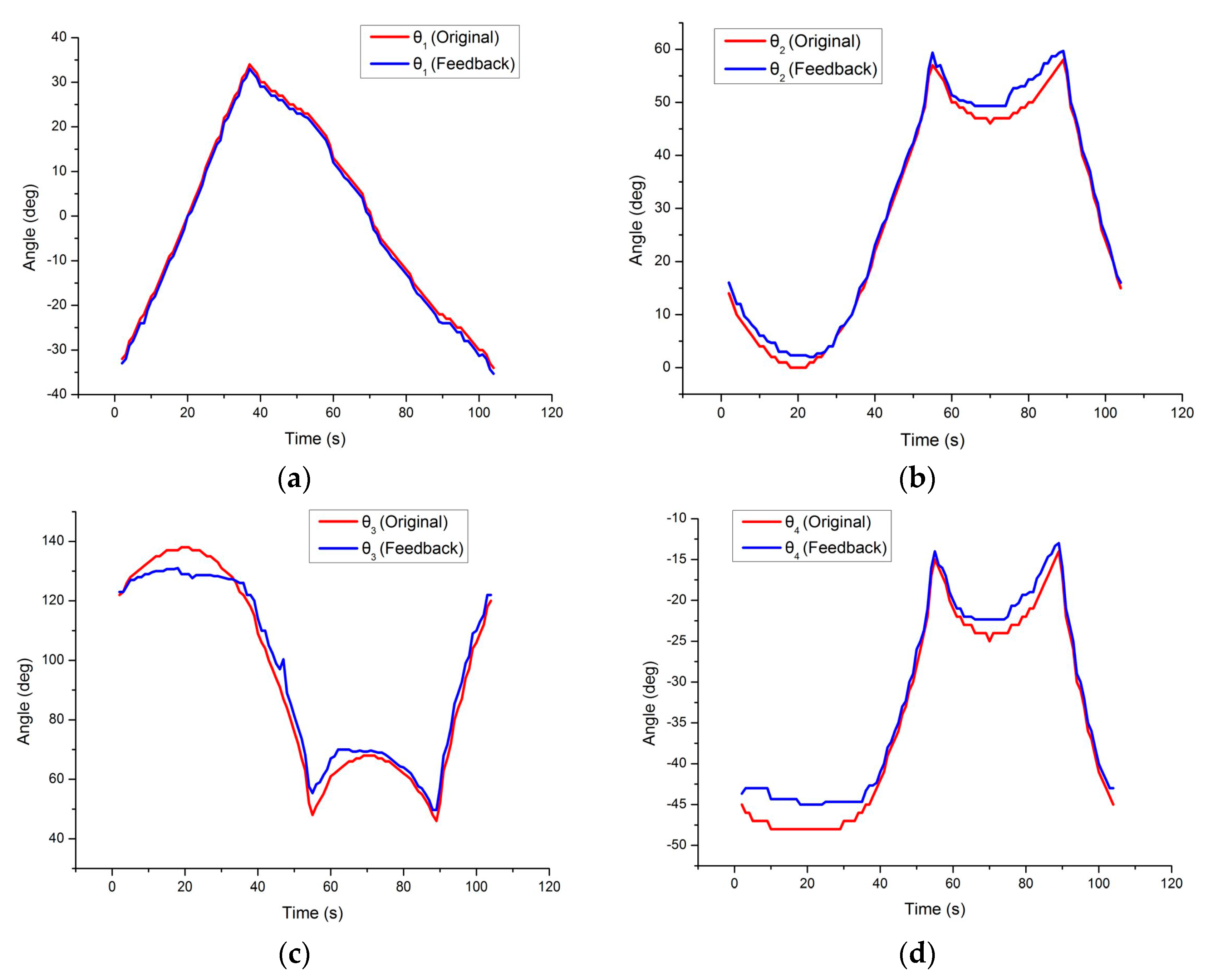
Figure 9 shows the simulated and measured results of axis angles for all the servo motors. It was found that the actual angles of each axis drifted over time and this may have been due to noisy data from the servo motor position encoders. It was also found that the angular error of the robotic arm changed with different payloads.
The errors between the theoretical and measured angles for the 2nd and 3rd axes became larger with an increased payload. In the experiments, the average angle error for the 0-th axis was found to be 9.82%, the others were 17.41% for the first axis, 4.92% for the second axis, and 5.95% for the third axis.
3.2. Clamping Force and Barcode Identification
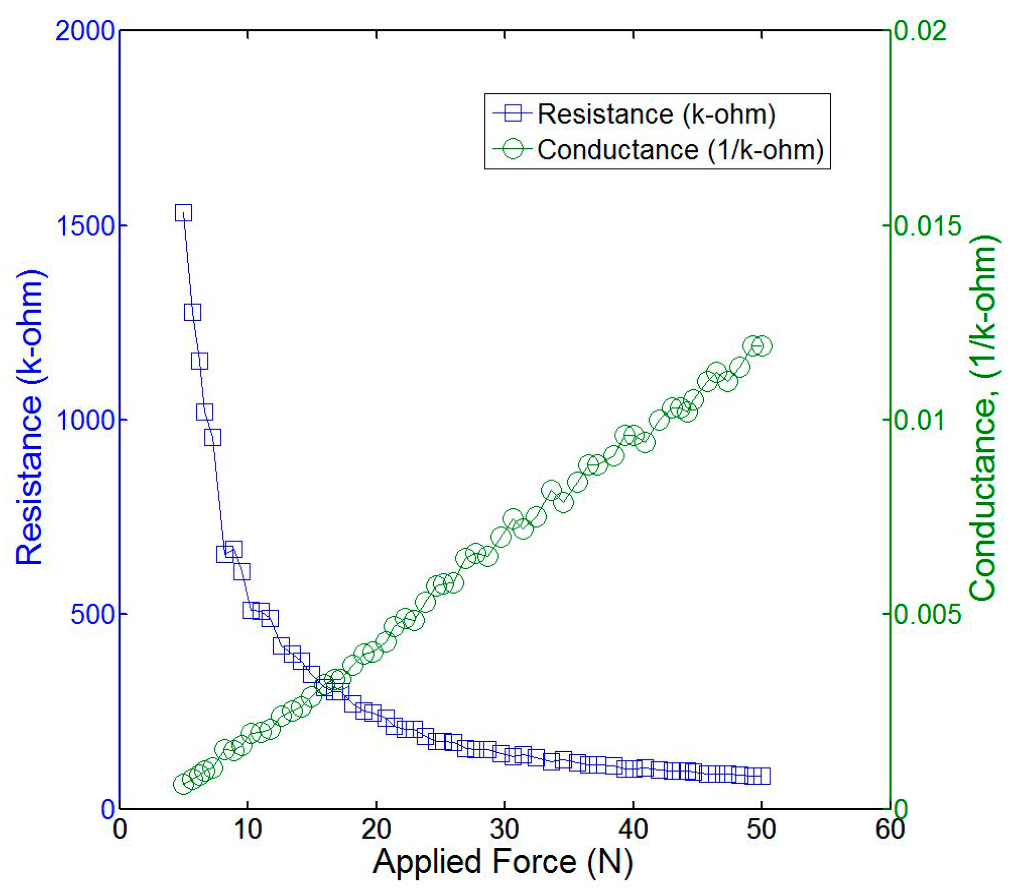
The force sensor (sensitivity of 0~111 N, Tekscan FlexiForce A301) installed on the gripper was tested to show the relationship between detected force and electrical resistance and conductivity. The experimental response of the sensor to an applied force in a range of 5~50 N is shown in Figure 10. An approximately linear relationship of the electrical conductance response of the sensor allows it to be accurately calibrated and used to measure the clamping force of the fingers of the gripper.
A regular web camera was used for one-dimensional barcode identification. Some of the EAN barcodes used by most retailers everywhere are shown in Figure 11, illustrating the algorithm of bar code recognition [21,22]. First, A in the figure is the original image captured by the camera, and the identified barcode is outlined by a green rectangle via comparison to preset thresholding values for edge detection; Secondly, B is a transformed binary image in grayscale from original color one, in which the white area represents the position of the barcode; Thirdly, C is the identified barcode ready for dimension reading of binary black and white stripes based on the EAN code; Finally, D shows the content transformation of the barcode displayed in the command bar, successively showing the decoded 13 digital numbers. The experimental results showed that the minimum proportion of 50% of a barcode could be correctly captured and identified at a maximum distance of 19 cm, thereby reaching a success rate of approximately 100% under normal test circumstances.
3.3. AGraphic User Interface (GUI) with an Embedded Computer
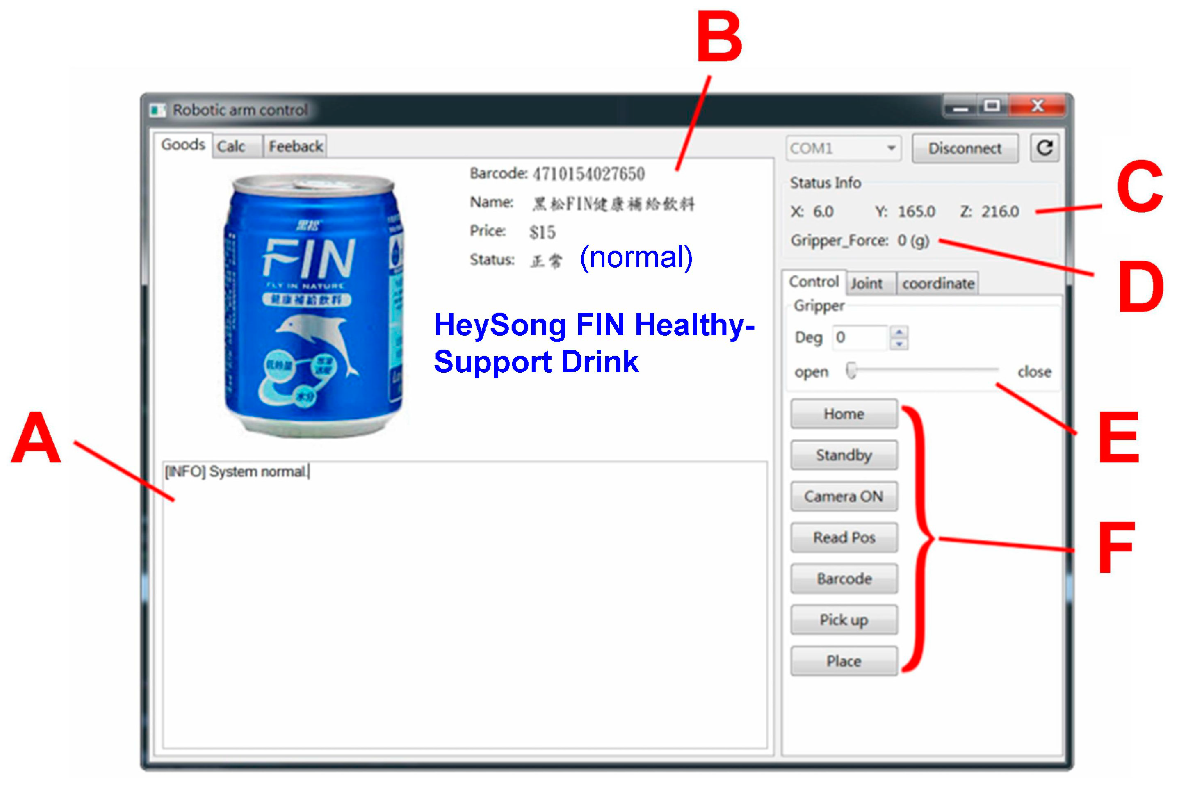
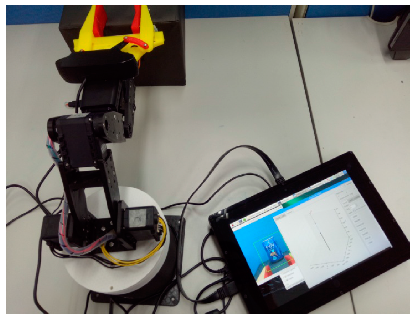
The graphics user interface (GUI) of the APP that enables the robot arm to perform computer vision bar code identification and goods inventory is shown in Figure 12. As mentioned earlier, the web camera captures the barcode image and uses the data to find the corresponding information about the object to determine if it was correctly placed. If the placement was wrong, the robot would pick up and remove the object. Please note, thus far, the position of object was pre-determined by the user because of no distance sensor was used here. This could be further implemented in the future. Finally, the overall GUI system was integrated into an embedded computer (Raspberry Pi) with a 10-inch touch screen as shown in Figure 13. Intuitive control of the robotic arm could be achieved by simply touching the command buttons.
4. Conclusions
In this study, we designed and fabricated a 6-axis robotic arm with a gripper for picking and placing products on shelves for inventory control. The gripper had real-time force sensors that controlled the different clamping force that was required for each kind of product to avoid damage by crushing. The mechanical design ensured that the force was applied uniformly to the sensor to avoid the chance of inaccurate measurement. Inverse kinematics coordinate conversion was implemented which showed an error of less than 3.3% caused by insufficient torque servomotor actuation. Camera vision allowed the simple operation of the robot using a graphic user interface (GUI), and product recognition from the barcode was straightforward. We anticipate that this kind of robot will play an important role in commodity management and the inventory of goods in supermarkets and retail stores.
Acknowledgments
This work is partially supported for 3D Innovative Self-Fabrication Lab by Department of Mechanical Engineering, National Kaohsiung University of Science and Technology (Former National Kaohsiung University of Applied Sciences), Kaohsiung, Taiwan. The authors are also grateful to 2017 SPINTECH Technology Thesis Awards, Taiwan, for comments on the work.
Author Contributions
Both authors contributed to the writing of the manuscript. Chin-Tai Chen conceived of the concept and supervised conducting of the experiments; Zhi-Ying Chen designed and performed the experiments. Both authors contributed to data analysis.
Conflicts of Interest
The authors declare no conflict of interest.
References
- Borgia, E. The internet of things: Key features, applications and open issues. Comput. Commmun. 2014, 54, 1–31. [Google Scholar] [CrossRef]
- McEvoy, M.A.; Correll, N. Materials that couple sensing, actuation, computation communication. Science 2015, 347, 1261689. [Google Scholar] [CrossRef] [PubMed]
- Manzoor, S.; Islam, R.U.; Khalid, A.; Samad, A.; Iqbal, J. An open-source multi-DOF articulated robotic educational platform for autonomous object manipulation. Robot. Comput. Integr. Manuf. 2014, 30, 351–362. [Google Scholar] [CrossRef]
- Lin, C.H. Vision servo based delta robot to pick-and-place moving parts. In Proceedings of the International Conference on Industrial Technology, Taipei, Taiwan, 14–17 March 2016. [Google Scholar]
- Kamei, K.; Shinozawa, K.; Ikeda, T.; Utsumi, A.; Miyashita, T.; Hagita, N. Recommendation from robots in a real-world retail shop. In Proceedings of the International Conference on Multimodal Interfaces, Beijing, China, 8–10 November 2010. [Google Scholar]
- Gruen, T.W.; Corsten, D. A Comprehensive Guide to Retail Out-Of-Stock Reduction in the Fast-Moving Consumer Goods Industry; Grocery Manufacturers of America: Arlington, VA, USA, 2007. [Google Scholar]
- Kejriwal, N.; Garg, S.; Kumar, S. Product counting using images with application to robot-based retail stock assessment. In Proceedings of the IEEE International Conference on Technologies for Practical Robot Applications, Woburn, MA, USA, 11–12 May 2015. [Google Scholar]
- Corsten, D.; Gruen, T. Desperately seeking shelf availability: An examination of the extent, the causes, and the efforts to address retail out-of-stocks. Int. J. Retail Distrib. Manag. 2003, 31, 605–617. [Google Scholar] [CrossRef]
- Zhang, J.; Lyu, Y.; Roppel, T.; Patton, J.; Senthilkumar, C.P. Mobile Robot for Retail Inventory Using RFID. In Proceedings of the IEEE International Conference on Industrial Technology, Taipei, Taiwan, 14–17 March 2016. [Google Scholar]
- McFarland, M. Why This Robot May Soon Be Cruising down Your Grocery Store’s Aisles. In the Washington Post. Available online: https://www.washingtonpost.com/news/innovations/wp/2015/11/10 (accessed on 10 November 2015).
- Youssef, S.M.; Salem, R.M. Automated barcode recognition for smart identification and inspection automation. Expert Syst. Appl. 2007, 33, 968–977. [Google Scholar] [CrossRef]
- Wakaumi, H.; Nagasawa, C. A ternary barcode detection system with a pattern-adaptable dual threshold. Sens. Actuators A Phys. 2006, 130–131, 176–183. [Google Scholar] [CrossRef]
- Bockenkamp, A.; Weichert, F.; Rudall, Y.; Prasse, C. Automatic robot-based unloading of goods out of dynamic AGVs within logistic environments. In Commercial Transport; Clausen, U., Friedrich, H., Thaller, C., Geiger, C., Eds.; Springer: New York, NY, USA, 2016; pp. 397–412. [Google Scholar]
- Zwicker, C.; Reinhart, G. Human-robot-collaboration System for a universal packaging cell for heavy goods. In Enabling Manufacturing Competitiveness and Economic Sustainability; Zaeh, M., Ed.; Springer: New York, NY, USA, 2014; pp. 195–199. [Google Scholar]
- Wilf, P.; Zhang, S.; Chikkerur, S.; Little, S.A. Computer vision cracks the leaf code. Proc. Natl. Acad. Sci. USA 2016, 113, 3305–3310. [Google Scholar] [CrossRef] [PubMed]
- Do, H.N.; Vo, M.T.; Vuong, B.Q.; Pham, H.T.; Nguyen, A.H.; Luong, H.Q. Automatic license plate recognition using mobile device. In Proceedings of the IEEE International Conference on Advanced Technologies for Communications, Hanoi, Vietnam, 12–14 October 2016. [Google Scholar]
- Choi, H.; Koç, M. Design and feasibility tests of a flexible gripper based on inflatable rubber pockets. Int. J. Mach. Tools Manuf. 2006, 1350–1361. [Google Scholar] [CrossRef]
- Russo, M.; Ceccarelli, M.; Corves, B.; Hüsing, M.; Lorenz, M.; Cafolla, D.; Carbone, G. Design and test of a gripper prototype for horticulture products. Robot. Comput. Integr. Manuf. 2017, 44, 266–275. [Google Scholar] [CrossRef]
- Rodriguez, F.; Moreno, J.C.; Sánchez, J.A.; Berenguel, M. Grasping in agriculture: State-of-the-art and main characteristics. In Grasping in Robotics; Carbone, G., Ed.; Springer: New York, NY, USA, 2013; pp. 385–409. [Google Scholar]
- Hartenberg, R.S.; Denavit, J. A kinematic notation for lower pair mechanisms based on matrices. J. Appl. Mech. 1955, 77, 215–221. [Google Scholar]
- Chai, D.; Hock, F. Locating and decoding EAN-13 barcodes from images captured by digital cameras. In Proceedings of the IEEE Fifth International Conference on Information, Communications and Signal Processing, Bangkok, Thailand, 6–9 December 2005. [Google Scholar]
- Canny, J. A computational approach to edge detection. IEEE Trans. Pattern Anal. Mach. Intell 1986, PAMI-8, 679–698. [Google Scholar] [CrossRef]
Figure 1.
The 6-axis robotic arm used in the study (unit: mm).
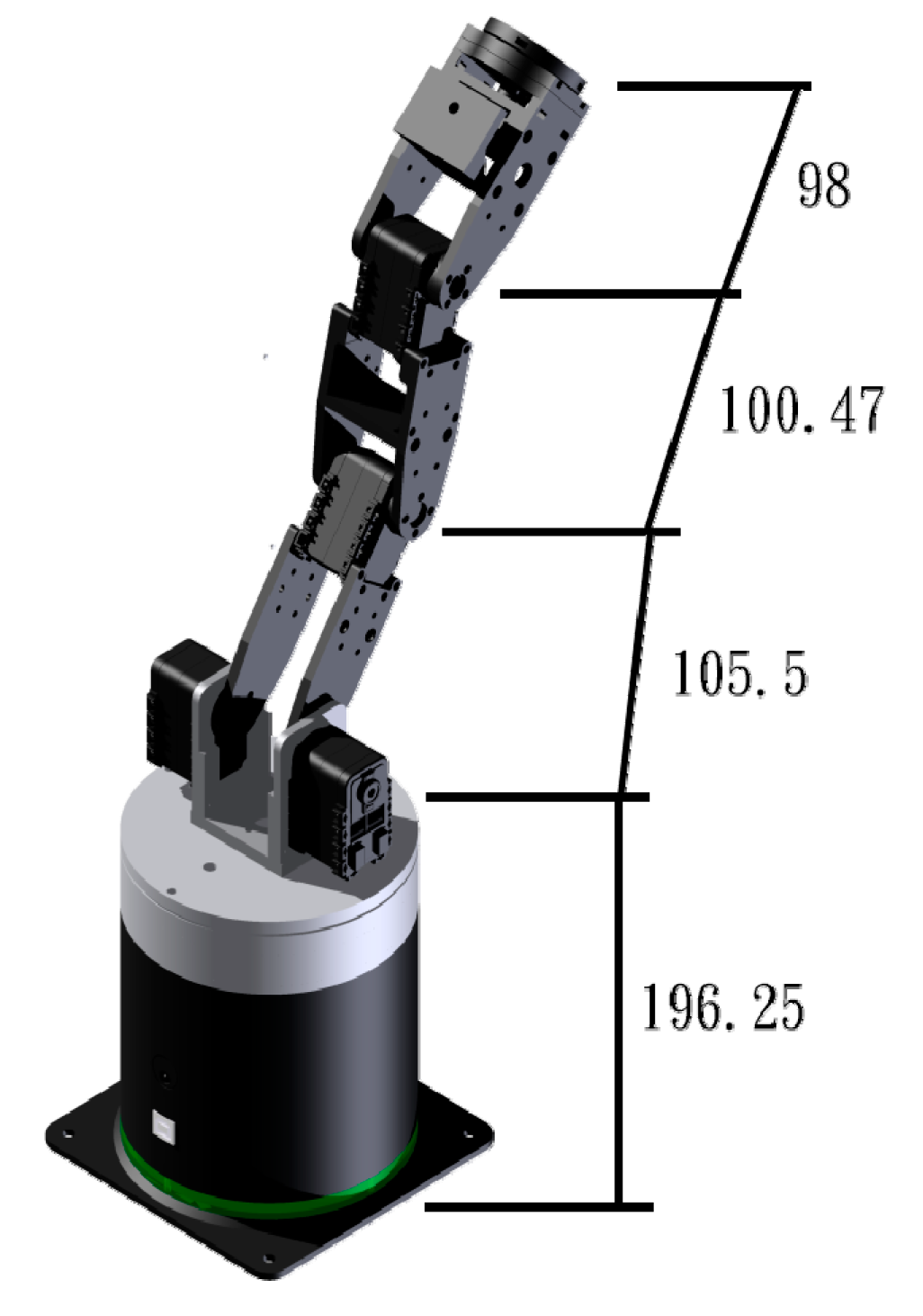
Figure 2.
Three different test packages: (a) A paper-foil milk tea drink; (b) An aluminum soda can; (c) A plastic box of biscuits.
Figure 2.
Three different test packages: (a) A paper-foil milk tea drink; (b) An aluminum soda can; (c) A plastic box of biscuits.

Figure 3.
The two-fingered gripper.

Figure 4.
Coordinate frames of the robot.

Figure 5.
A graphical interface simulation of robotic motion with four features including: (A) Simulation chart; (B) Kinematic mode; (C) Angle of each axis; and (D) Coordinates of each axis.
Figure 5.
A graphical interface simulation of robotic motion with four features including: (A) Simulation chart; (B) Kinematic mode; (C) Angle of each axis; and (D) Coordinates of each axis.
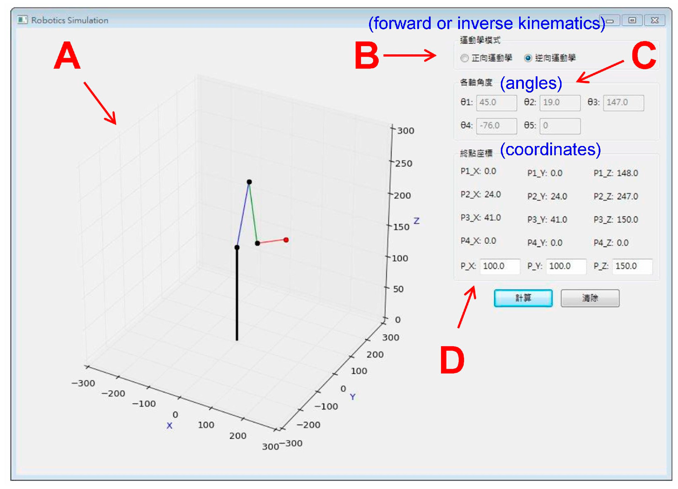
Figure 6.
Theoretical and measured paths for a robot arm moving along a rectangular path without a payload.
Figure 6.
Theoretical and measured paths for a robot arm moving along a rectangular path without a payload.

Figure 7.
The robot arm moving along a given rectangular path with no payload, showing the theoretical and measured angular changes over time for each axis: (a) Axis-0 (θ1); (b) Axis-1 (θ2); (c) Axis-2 (θ3); (d) Axis-3 (θ4).
Figure 7.
The robot arm moving along a given rectangular path with no payload, showing the theoretical and measured angular changes over time for each axis: (a) Axis-0 (θ1); (b) Axis-1 (θ2); (c) Axis-2 (θ3); (d) Axis-3 (θ4).

Figure 8.
Theoretical and measured paths for a robot arm moving along a rectangular path with a payload.
Figure 8.
Theoretical and measured paths for a robot arm moving along a rectangular path with a payload.
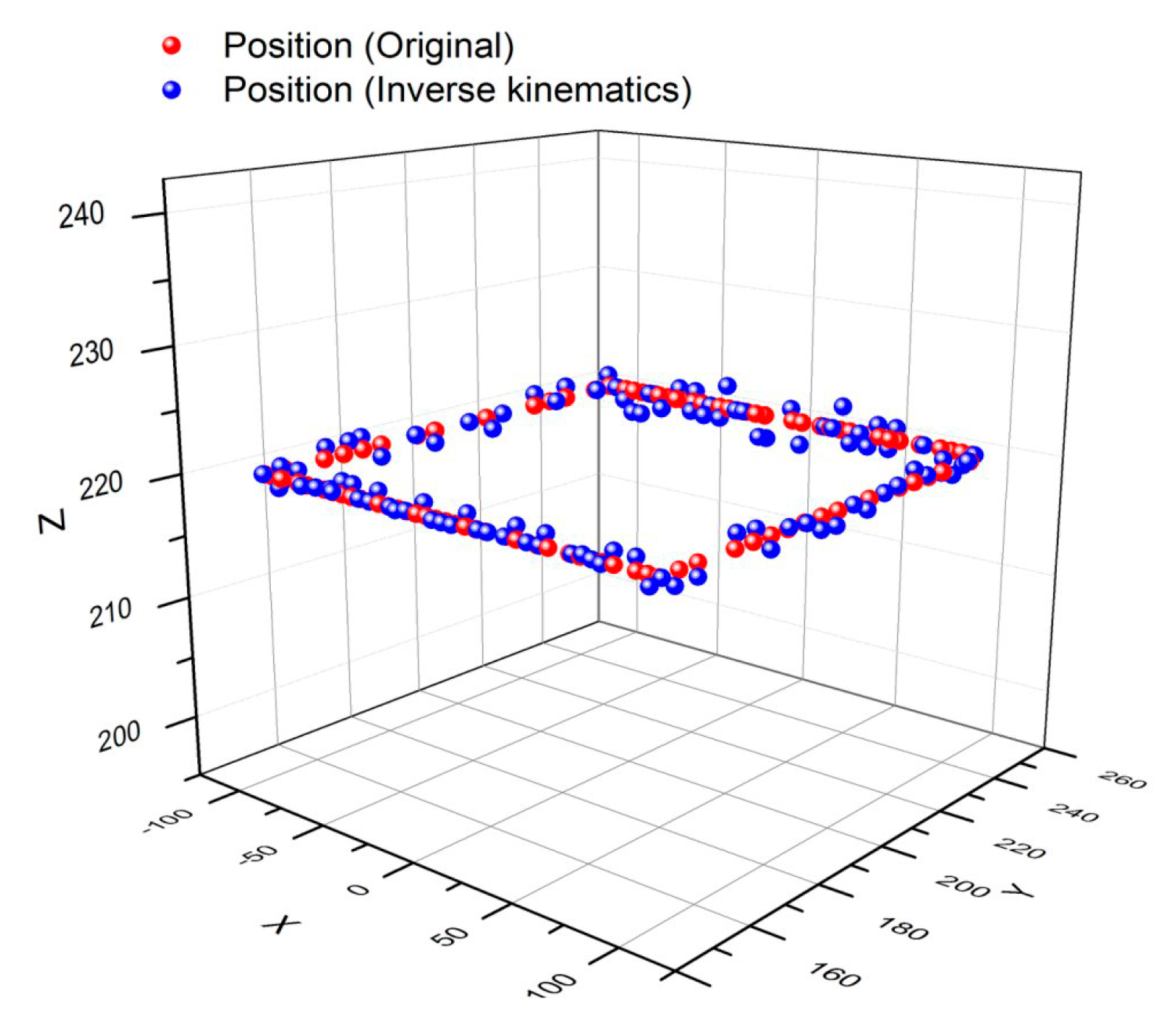
Figure 9.
The theoretical and measured angular changes in each axis of the robot arm carrying an object and moving along a given rectangular path: (a) Axis-0 (θ1); (b) Axis-1 (θ2); (c) Axis-2 (θ3); (d) Axis-3 (θ4).
Figure 9.
The theoretical and measured angular changes in each axis of the robot arm carrying an object and moving along a given rectangular path: (a) Axis-0 (θ1); (b) Axis-1 (θ2); (c) Axis-2 (θ3); (d) Axis-3 (θ4).

Figure 10.
The electrical resistance and conductance of the sensor corresponding to an applied force.
Figure 10.
The electrical resistance and conductance of the sensor corresponding to an applied force.

Figure 11.
The experimental results of barcode identification with four parts including: (A) An original image; (B) A binary image; (C) A region of interest; and (D) Digital contents of the barcodes.
Figure 11.
The experimental results of barcode identification with four parts including: (A) An original image; (B) A binary image; (C) A region of interest; and (D) Digital contents of the barcodes.

Figure 12.
The graphic user interface (GUI) with six parts including: (A) System status; (B) Goods information; (C) Coordinates of the end actuator; (D) Clamping force; (E) Clamping on/off switch, and (F) Control instructions.
Figure 12.
The graphic user interface (GUI) with six parts including: (A) System status; (B) Goods information; (C) Coordinates of the end actuator; (D) Clamping force; (E) Clamping on/off switch, and (F) Control instructions.

Figure 13.
The robotic arm GUI in the Raspberry Pi via a 10-inch touch-screen tablet computer.


Table 1.
The Denavit-Hartenberg (D-H) parameters of the robotic arm.
| Axis | èi (deg) | di (mm) | ai (mm) | ái (deg) |
|---|---|---|---|---|
| 0 | è1 | 0 | 0 | 90° |
| 1 | è2 | 196.25 | 0 | 0° |
| 2 | è3 − 90° | 0 | 105.5 | 0° |
| 3 | è4 − 90° | 0 | 100.4 | 0° |
| 4 | 0° | 98 | 0 | 0° |
| 5 | 0° | 165 | 0 | 0° |
© 2018 by the authors. Licensee MDPI, Basel, Switzerland. This article is an open access article distributed under the terms and conditions of the Creative Commons Attribution (CC BY) license (http://creativecommons.org/licenses/by/4.0/).
Share and Cite
MDPI and ACS Style
Chen, Z.-Y.; Chen, C.-T. A Remote Controlled Robotic Arm That Reads Barcodes and Handles Products. Inventions 2018, 3, 17. https://doi.org/10.3390/inventions3010017
AMA Style
Chen Z-Y, Chen C-T. A Remote Controlled Robotic Arm That Reads Barcodes and Handles Products. Inventions. 2018; 3(1):17. https://doi.org/10.3390/inventions3010017
Chicago/Turabian StyleChen, Zhi-Ying, and Chin-Tai Chen. 2018. "A Remote Controlled Robotic Arm That Reads Barcodes and Handles Products" Inventions 3, no. 1: 17. https://doi.org/10.3390/inventions3010017