1. Introduction
Since their introduction in the 1930’s, cyclotrons play an important part in the production of radionuclides in a variety of applications, from basic physics, to agriculture and medicine [
1]. At TRUMF, several cyclotrons and beam lines are dedicated to the production of medical isotopes for imaging and therapy [
2]. The Life Sciences division employs the TR13 cyclotron [
3,
4], a 13 MeV negative-hydrogen machine, to produce most of their isotopes in gaseous, liquids and solid targets (e.g.
11C,
13N,
18F,
44Sc,
52Mn,
55Co,
61/64Cu,
68Ga,
86Y,
89Zr,
94mTc,
117/118/119Sb,
192Ir,
203Pb) [
5].
One of the main components of a cyclotron is the ion source where the projectile beam is created. While this can be protons, negative hydrogen ions, or deuterons, negative hydrogen ions are favoured [
6] as the beam can be extracted from the cyclotron via a stripping foil in the acceleration plane. The ions pass through a carbon stripper foil, changing their charge from −1 to +1 and therefore changing their trajectory in the magnetic field of the cyclotron [
7] and leading to beam extraction onto a target. The TR13 cyclotron operates with an external multi-cusp negative ion source. This causes less activation and consequently lower personnel dose and radioactive waste during maintenance and decommissioning of the cyclotron than with an internal ion source [
8]. General information about ion sources can be found in [
9].
To create negative hydrogen ions, ultra-high purity hydrogen gas is flowing into the ion source chamber, where the ions are created, which are then accelerated into the plane of the cyclotron. To achieve this, a tantalum filament is heated via a high current to create electrons. A bias voltage is applied between the filament and the chamber wall to control the ionization. These electrons form a plasma, which is held in place by rare-earth magnets placed in several rings in the chamber (see
Figure 1). A fast-feedback loop constantly monitors in real-time the value of the arc current between the filament and the chamber of the wall, and adjusts the filament current to maintain the arc current at a constant pre-set level. The H
− ions are formed in the plasma. Several mechanisms are competing for the H
− production and destruction (ν vibrational sate) [
7]:
| H− Production: | | |
| H2* (ν ≥ 4) + e (~0.5 eV) → H− + H | Dissociative electron attachment, | σ = ~1.6 × 10⁻¹⁶ cm2 |
| H2 + e (~3.7 eV) → H− + H* | Dissociative electron attachment, | σ = ~1.6 × 10⁻²¹ cm2 |
| H2 (ν = 0) + e (~38 eV) H− + H+ + e | Polar dissociation, | σ = ~1.6 × 10⁻²⁰ cm2 |
| H− Destruction: | | |
| H− + H2 → H2 + H | Charge transfer, | σ = 2.5 × 10⁻¹³ cm2 |
| H− + e (≥15 eV) → H + 2e | Collisional detachment, | σ = 4 × 10⁻¹⁵ cm2 |
| H− + H2 → H2 + H | Collisional detachment, | σ = 1 × 10⁻¹⁵ cm2 |
To successfully produce H
−, low and higher energy electrons from the ion source are therefore separated by the magnetic field arrangement, see [
7].
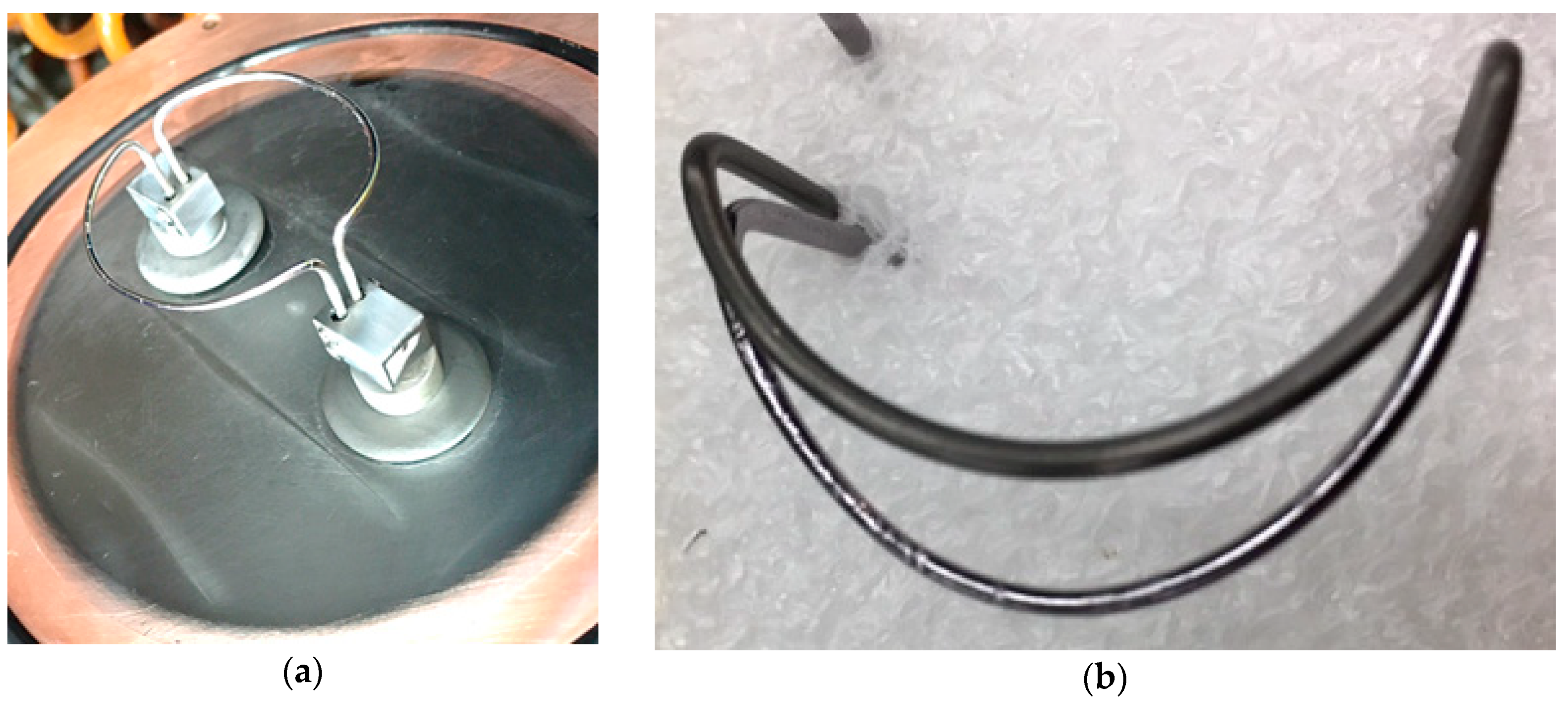
The filament design in the ion source of the TR13 cyclotron at TRIUMF has been in use for many years and is made of tantalum wire shaped like a half circle (Filament I), see
Figure 2a. The filament is mounted in duplicate on the removable end plate of the ion source for easy access. Over time, the tantalum wire of the filament loses material and wears thin, see
Figure 2b.
This is reflected in a dropping current flowing through Filament I during routine operation, see
Figure 3. To avoid filament breakage and therefore loss of negative hydrogen beam, the Filament I pair is being replaced when the current drops to about 100 A at the TR13. At normal operation Filament I in the ion source needs to be replaced on average every three months to ensure beam delivery, which causes the cyclotron to be off for a minimum of a day each time as the ion source chamber needs to be vented, shielding needs to be removed, services need to be disconnected, the backplate of the ion source needs to be removed and the filament needs to be replaced. The reverse is then necessary before operation can resume. To significantly shorten this down time, a new spiral filament, Filament II, designed for the 520 MeV cyclotron at TRIUMF [
5], was tested at the TR13 cyclotron.
2. Materials and Methods
The TR13 cyclotron, the work horse of the Life Sciences Division at TRIUMF, is a 13 MeV cyclotron with an external ion source, accelerating negative-hydrogen ions. For more details of the design and operation see [
3,
4]. The ion source relies on a filament for the production of negative hydrogen ions which are then transported into the plane of the cyclotron for acceleration and bombardment of medical isotope targets. The new Filament II was originally designed for the external ion source at the 520 MeV cyclotron at TRUMF and has already been described in [
7]. While a tantalum filament produces very bright H
− beams, it is also known to degrade fast [
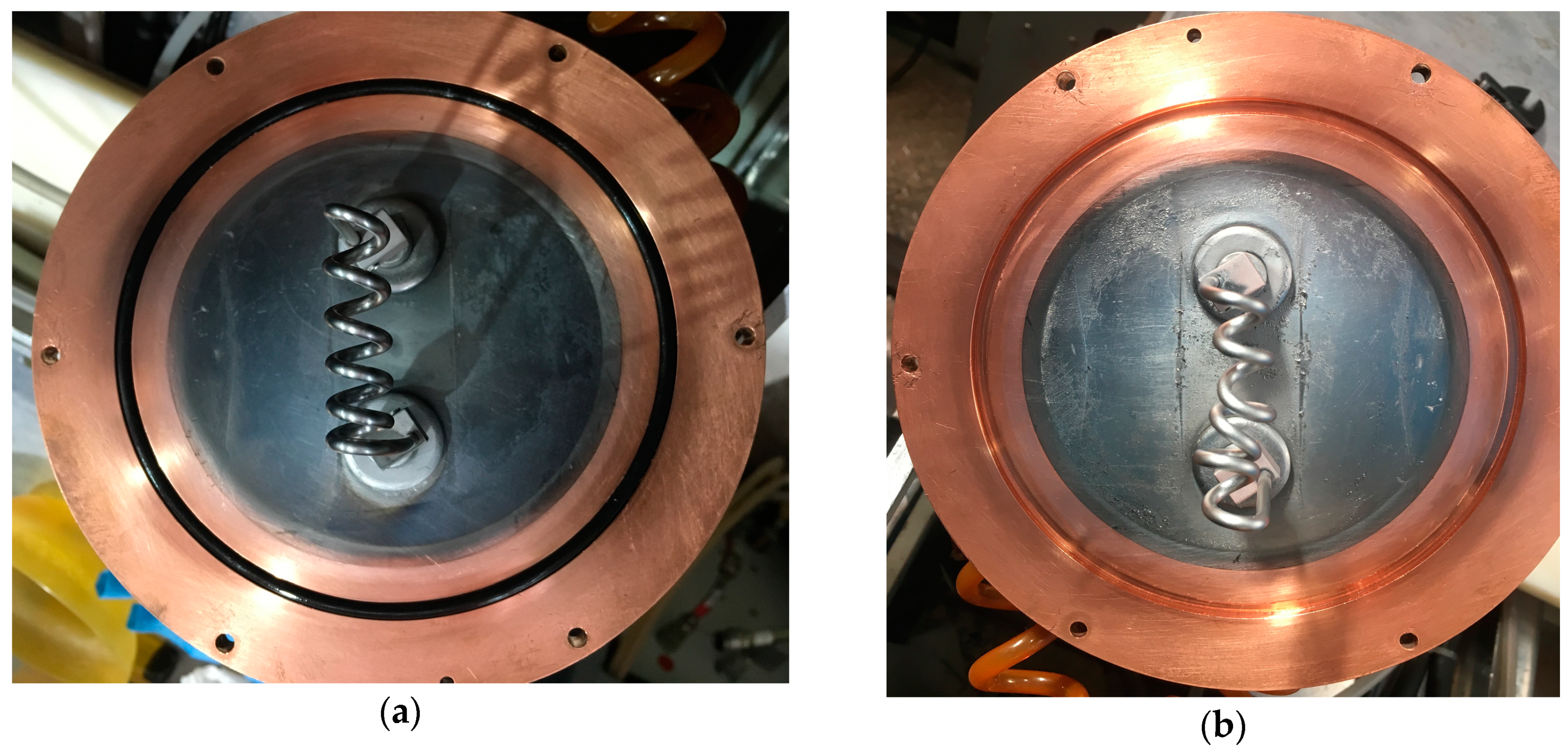
7]. The new Filament II is made from a tungsten alloy, which degrades slower. The Filament II is shaped in house. Several lengths and shapes were studied as mentioned in [
7] and the spiral filament in
Figure 4a with an outer spiral diameter of 10 mm and six windings achieved the longest lifetime. As this new Filament II is slightly thicker (3.0 mm versus 1.5 mm for Filament I), a higher current is needed to give the same surface temperature and electron emission. To hold the new filament wire, the mounting stands on the ion-source back plate (see
Figure 4) had to be modified to accept the 3.0 mm diameter. Due to the thicker wire, a higher filament current was necessary, 230 A at the beginning versus 150 A for Filament I. While our power supply (Xantrex, XKW, 12V and 250A) was able to provide this extra current, this should be taken into account when considering upgrading filaments. No other modification to the ion-source chamber, including the magnetic field, was necessary.
3. Results and Discussion
The operation of Filament II is the same as of the old Filament I. The automated routine tracking the currents and voltages was able to operate the new Filament II without any changes necessary.
Figure 5. shows the filament current of the new Filament II over time. At the beginning of this graph, Filament I was still in use with its start-up current of ~150 µA and a fast current-drop. Shortly before month 8, the new Filament II was installed. While the higher start-up current of ~230 A is obvious, it is also very clear that the filament current declines significantly slower than for Filament I. We estimate from the observed drop that Filament I could be in use for about two years before it needs to be replaced.
Also shown in
Figure 5 at around month 17, a sudden filament current drop down to 150 A was observed. This sudden drop was caused by the deformation of the spiral to the point that two neighboring windings touched and shorted, effectively shortening the filament length, see
Figure 4b. While this reduced the current output of the ions source due to the shorter active length and made tuning for higher beam currents difficult and tedious, it should be noted that it did not hinder routine isotope production. In month 20, the Filament II was replaced and the filament current consequently recovered to the previously observed 230 A.
Due to the higher current necessary to operate Filament II, a temperature rise in the electrical cables feeding into the ion source was observed, see
Figure 6. During operation, the cable supplying the new spiral filament rose to 47.0 °C. It should be noted that although our power supply is rated to provide the increased current as it is rated for up to 250 A, we plan on upgrading the supply in the future.


