
Roadmap on Recent Progress in FINCH Technology

 ,
,  , , , , , , , , ,
Abstract
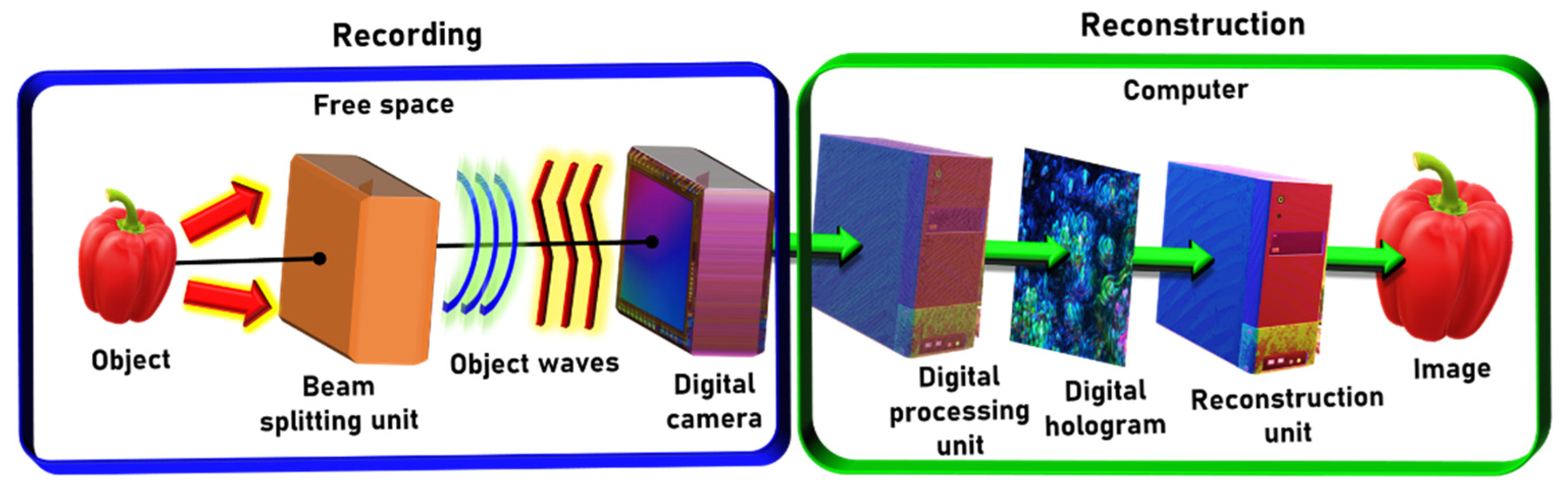
:1. Introduction (Joseph Rosen and Vijayakumar Anand)
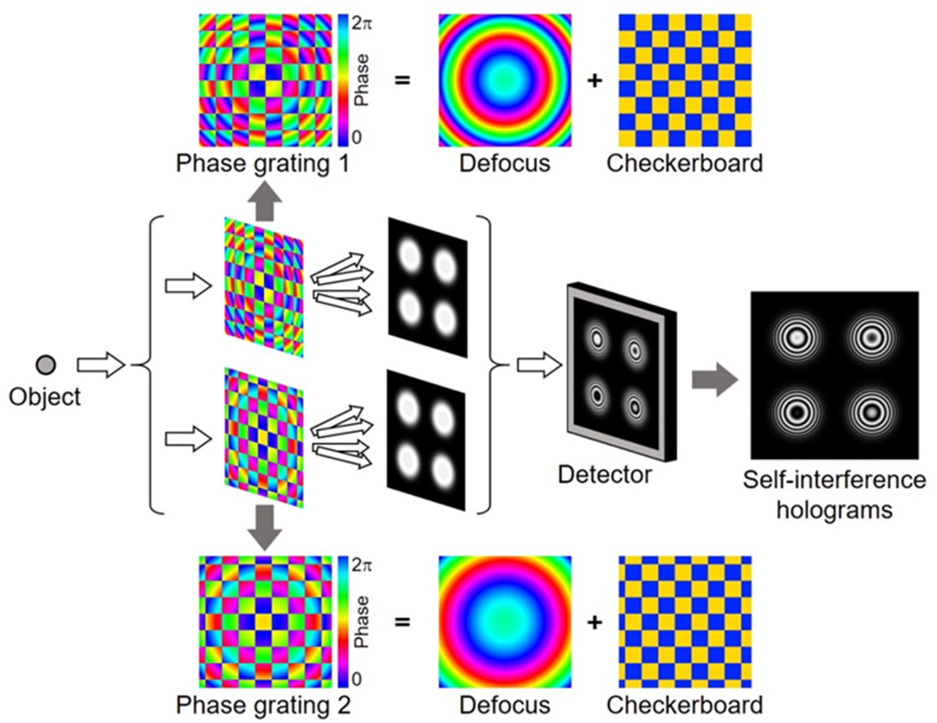
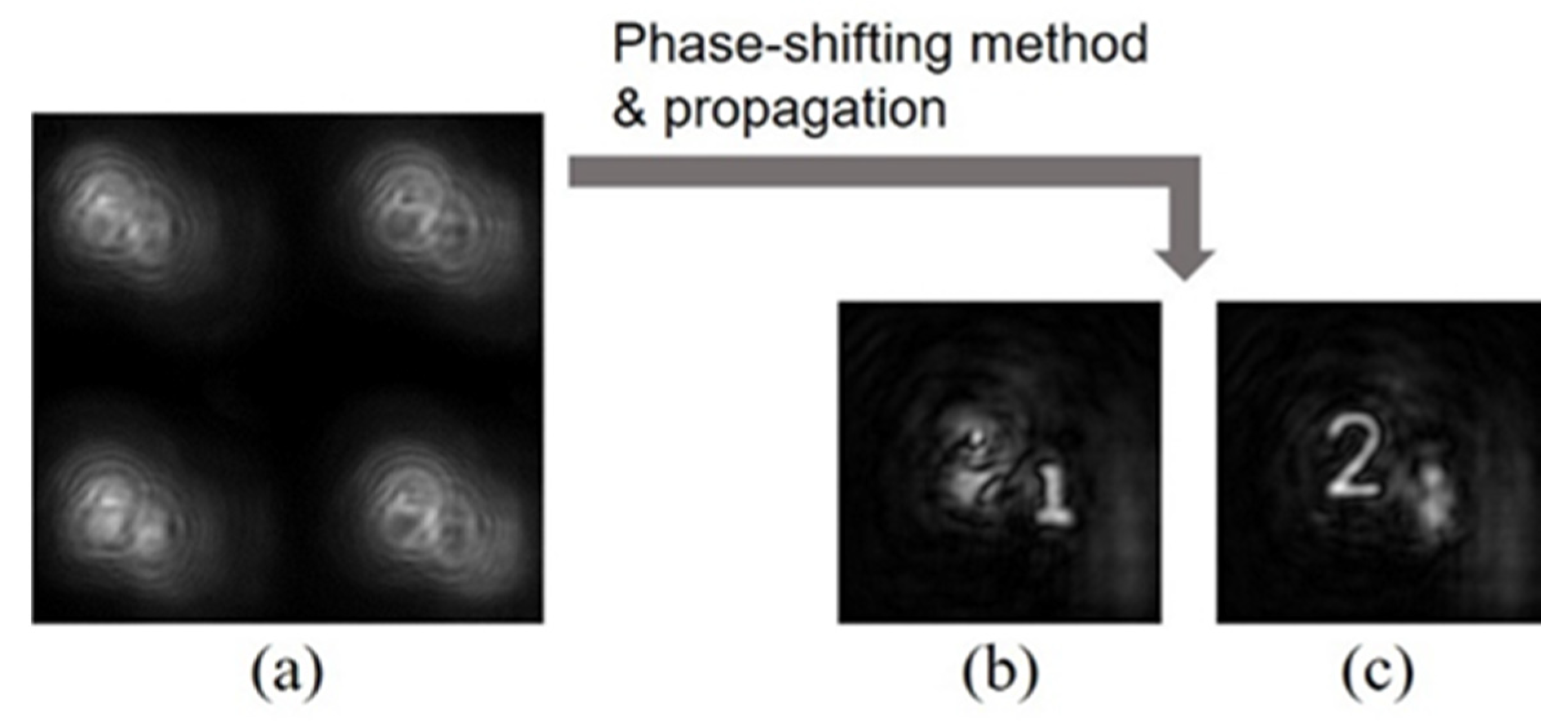
2. Single-Shot Phase-Shifting Fresnel Incoherent Correlation Holography with Dual-Phase Gratings (Teruyoshi Nobukawa)
2.1. Status
2.2. Future Challenges
2.3. Conclusions
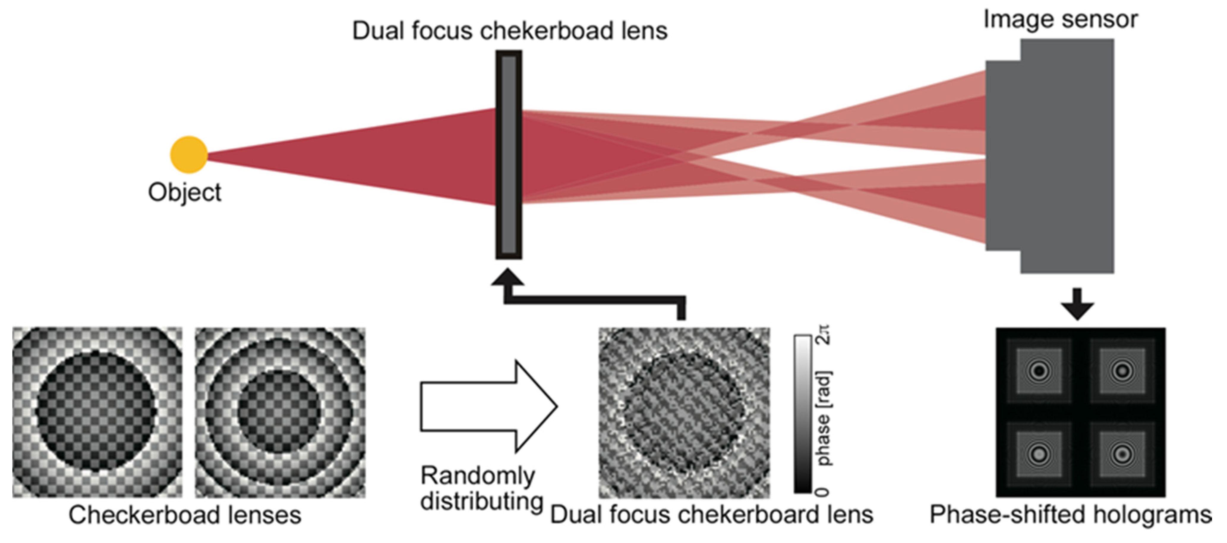
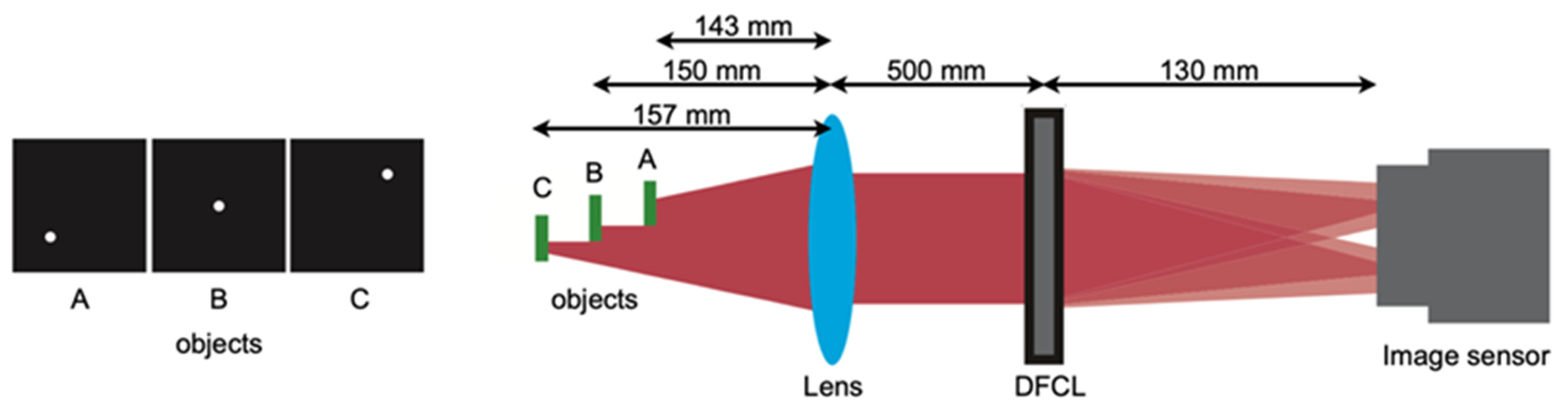
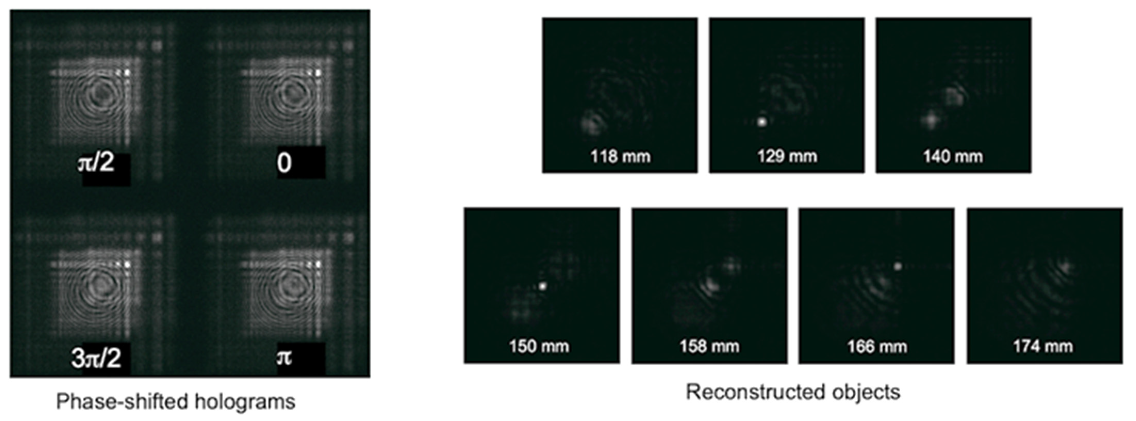
3. Parallel Phase-Shifting Single-Shot in-Line Fresnel Incoherent Correlation Holography Using a Dual-Focus Checkerboard Lens (Takanori Nomura)
3.1. Status
3.2. Conclusions
4. Single-Shot Fresnel Incoherent Digital Holography Based on Geometric Phase Lens (Dong Liang and Jun Liu)
4.1. Status
4.2. Conclusions
5. Fresnel Incoherent Correlation Holography with Non-Linear Reconstruction (Vijayakumar Anand and Saulius Juodkazis)
5.1. Status
5.2. Future Challenges
5.3. Conclusions
6. FINCH Based on Metasurfaces (Hongqiang Zhou and Lingling Huang)
6.1. Status
6.2. Current and Future Challenges
6.3. Advances of Metalens to Meet Challenges of FINCH
6.4. Concluding Remarks
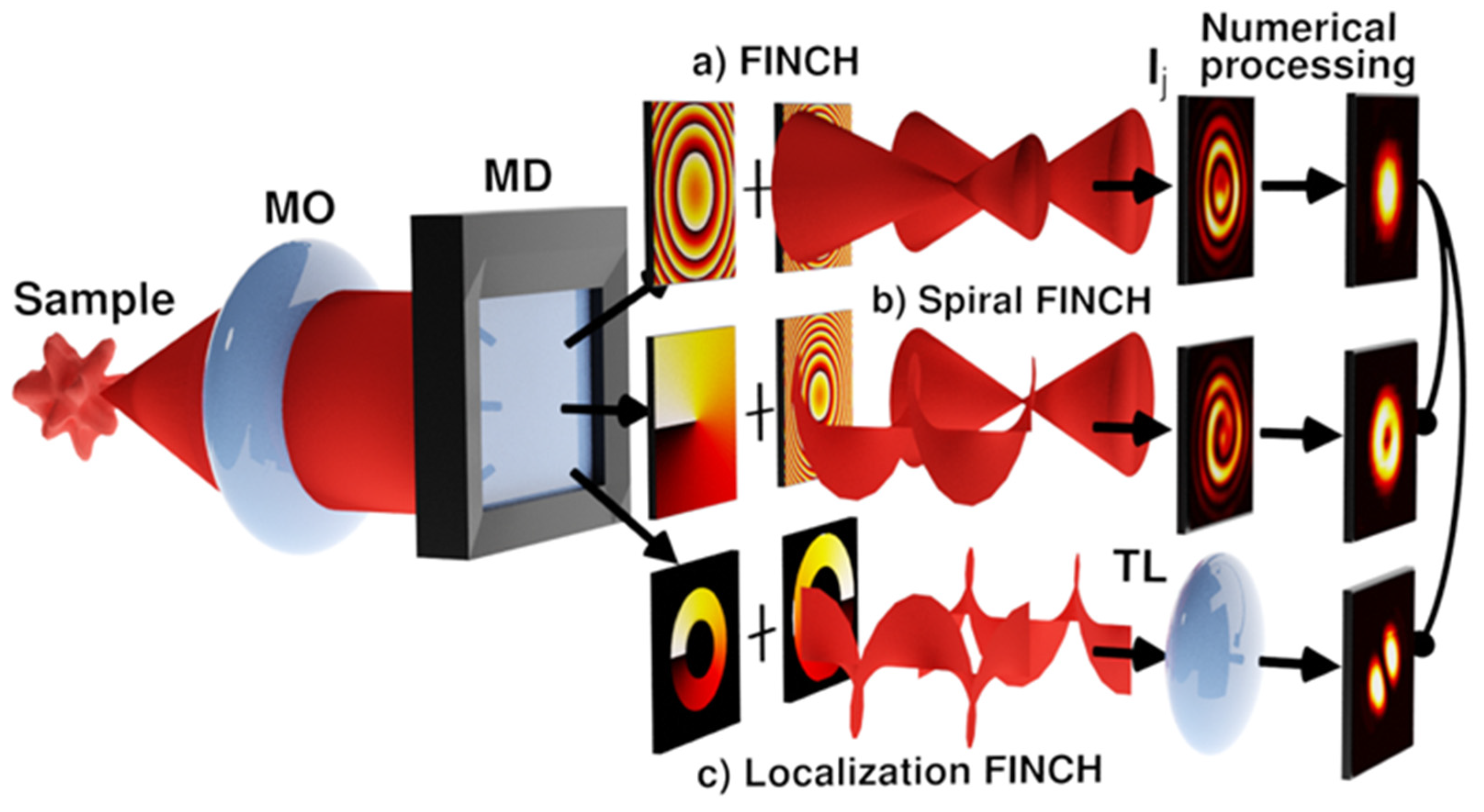
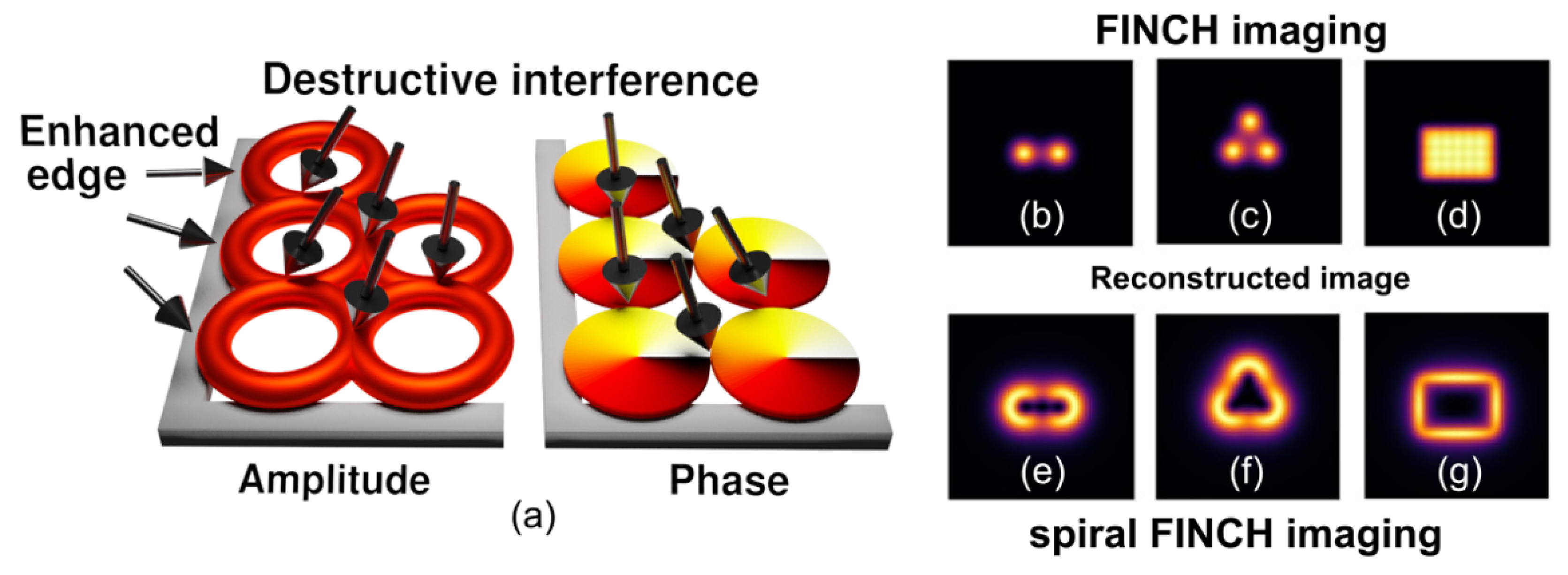
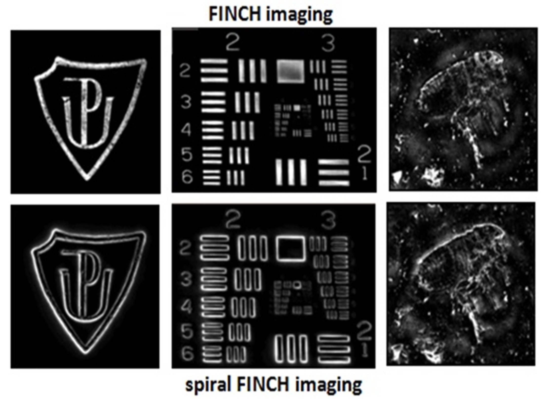
7. Vortex FINCH in Spiral and Localization Microscopy (Petr Bouchal and Zdeněk Bouchal)
7.1. Status
7.1.1. Demonstration of Spiral FINCH Imaging
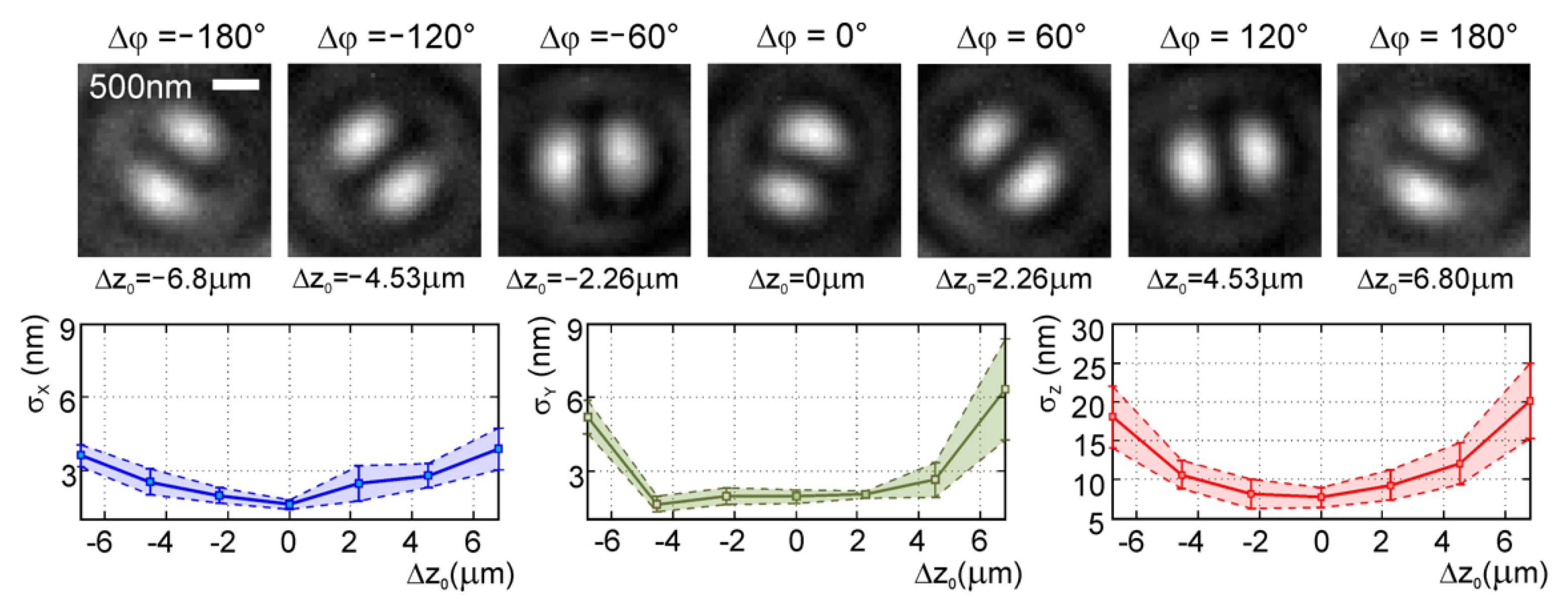
7.1.2. Demonstration of Localization FINCH Imaging
7.2. Conclusions
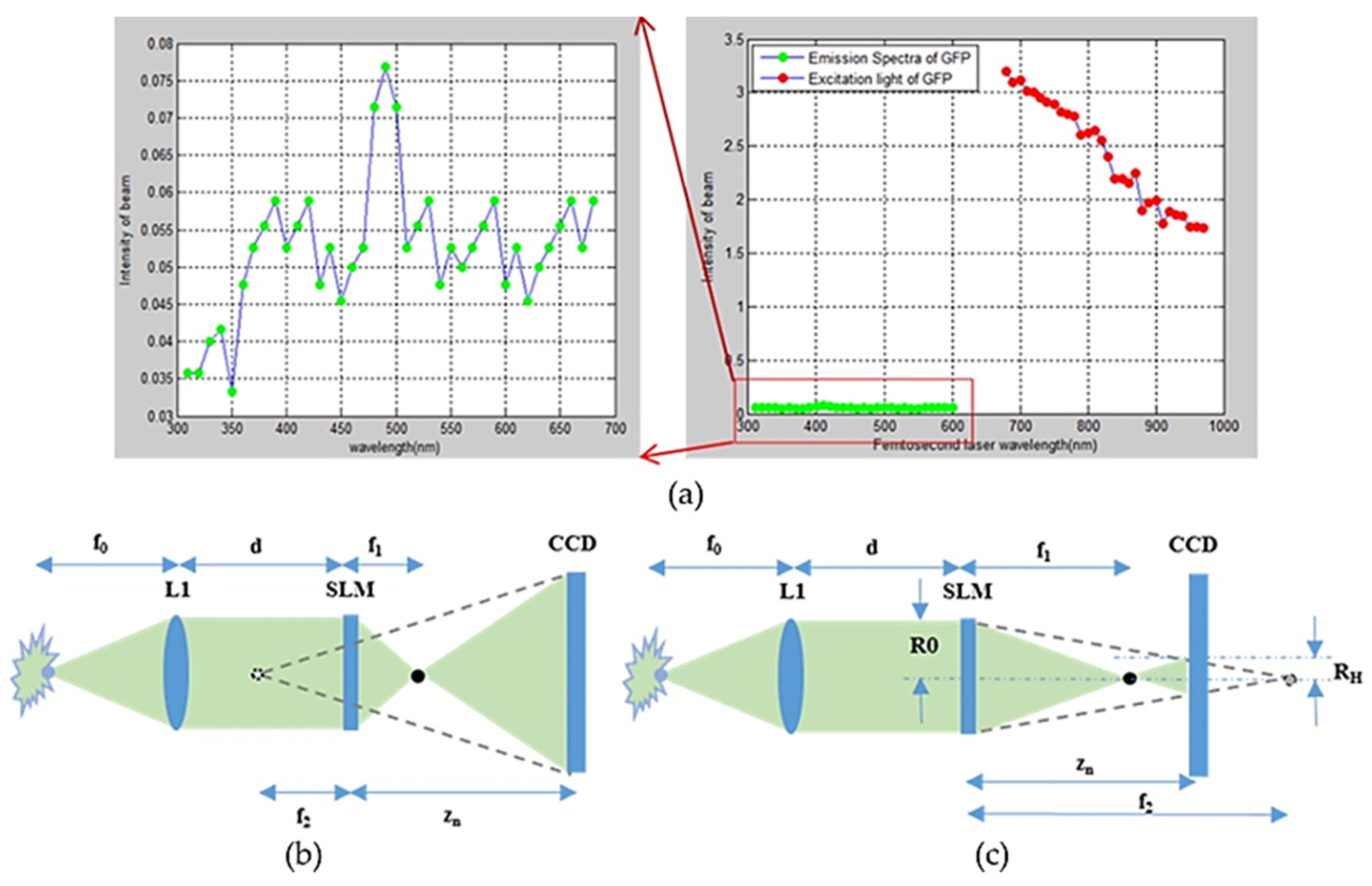
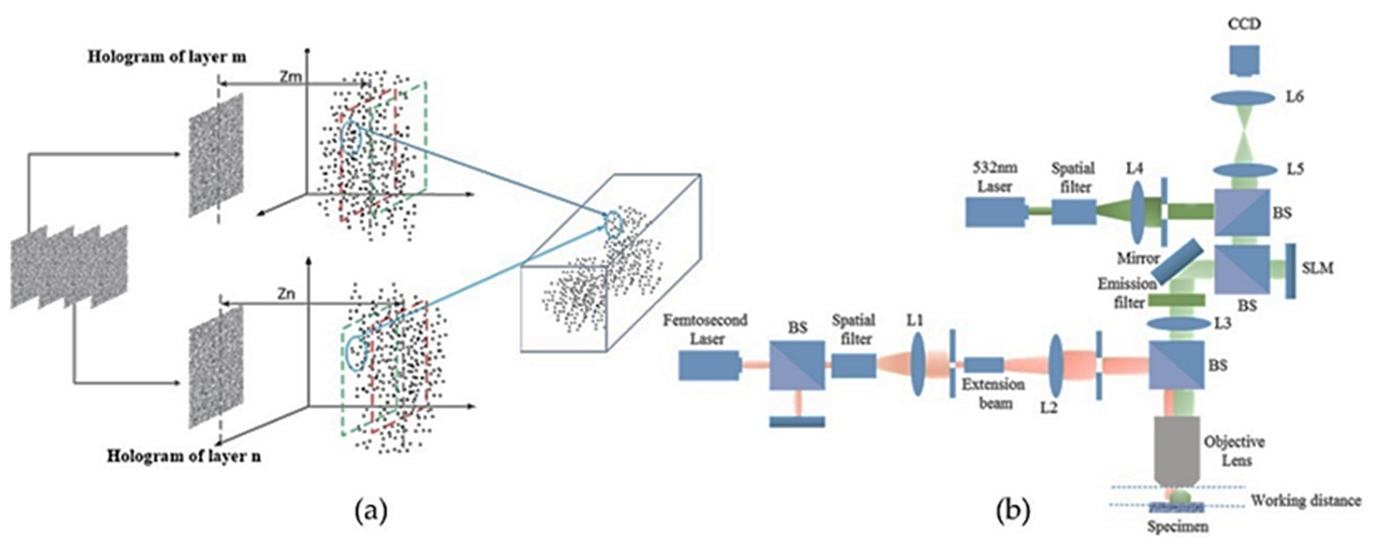
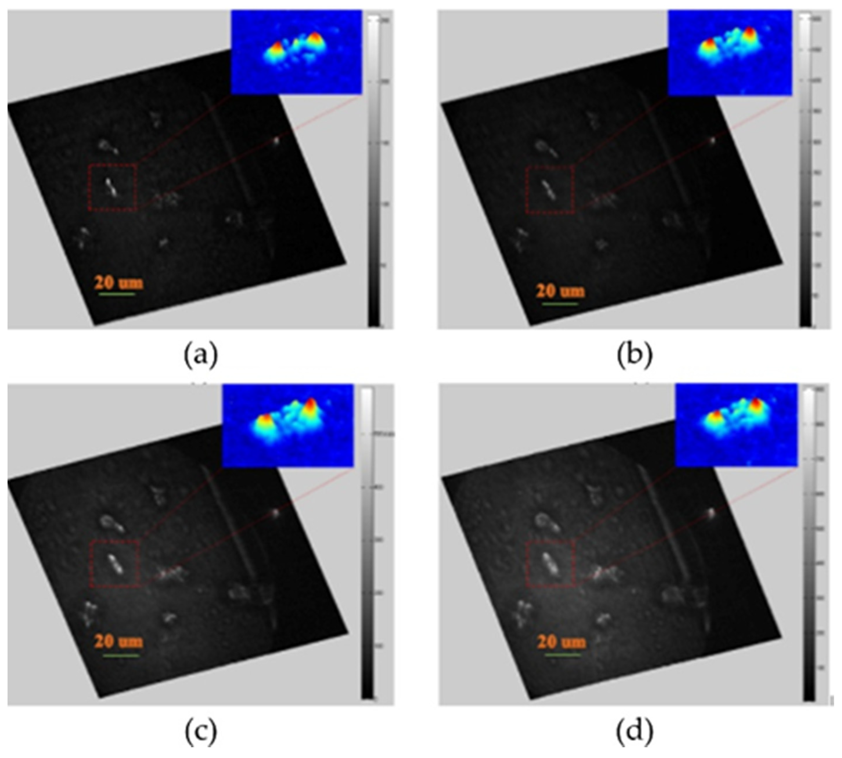
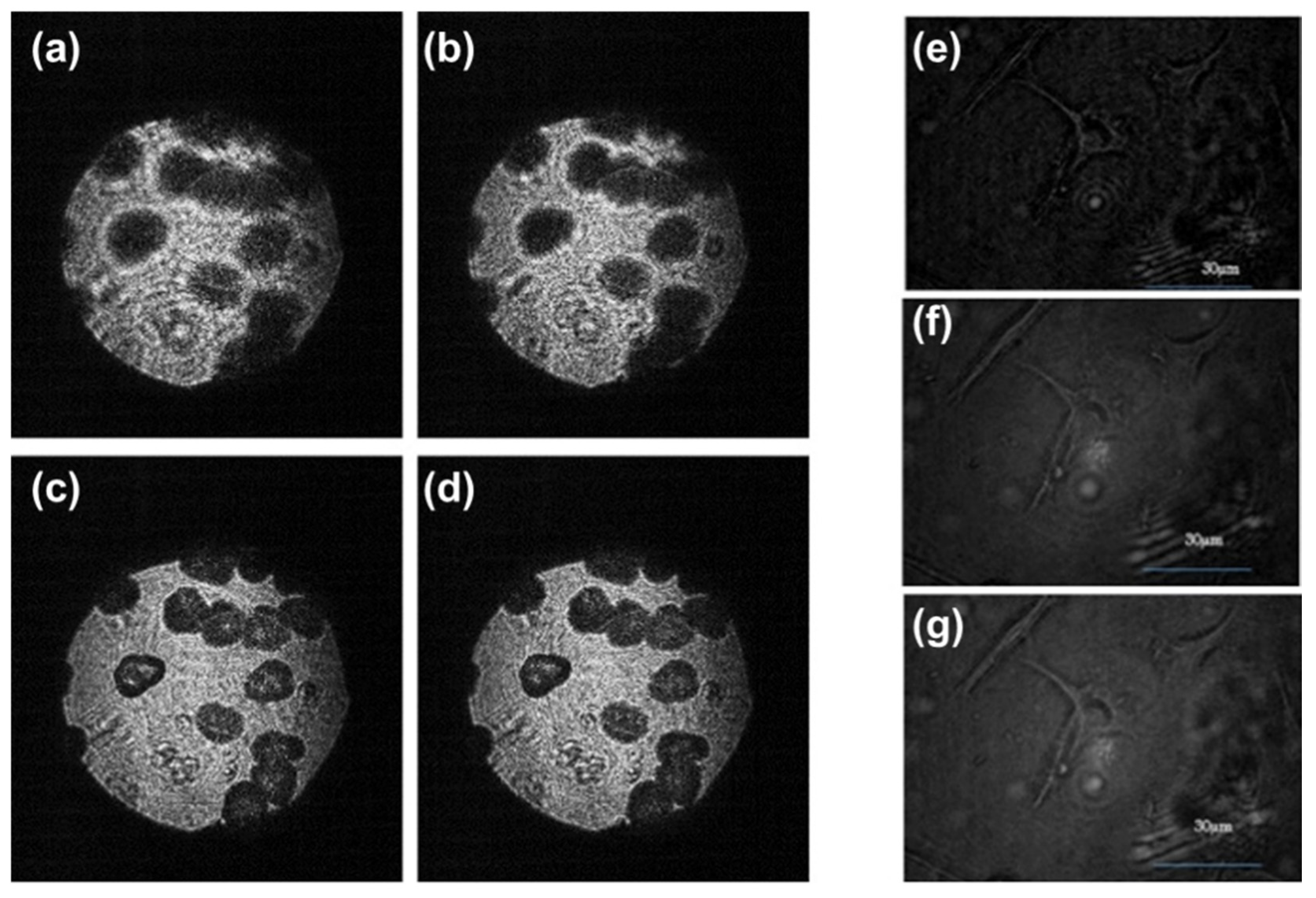
8. Three-Dimensional Reconstruction for Living Cell by Using a Femtosecond Laser-Based Phase-Shifting Fresnel Incoherent Digital Hologram (Bang Le Thanh, Munkh-Uchral Erdenebat, and Nam Kim)
8.1. Status
8.2. Conclusions
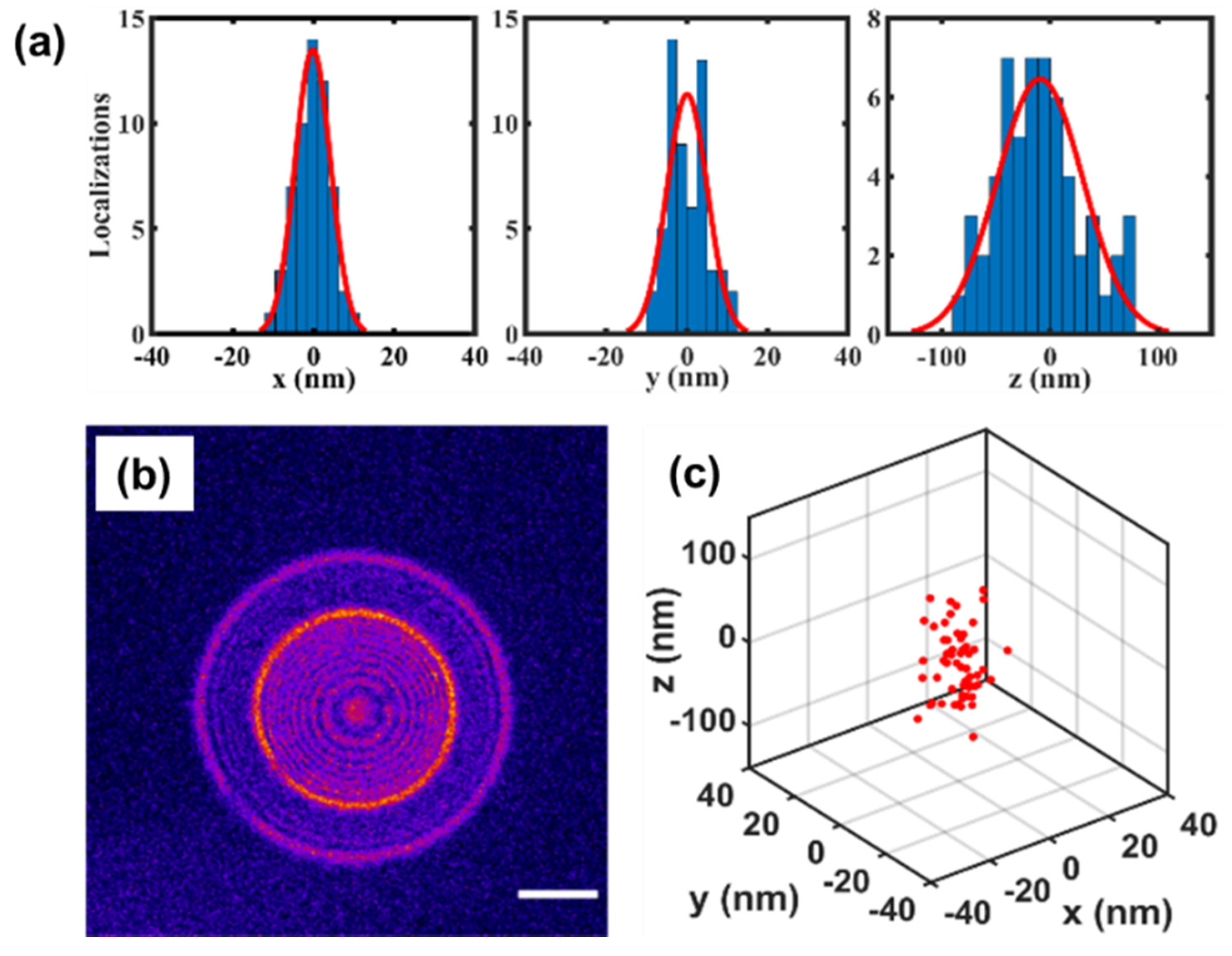
9. Single-Molecule Localization with FINCH (Peter Kner and Abhijit Marar)
9.1. Status
9.2. Future Work
9.3. Conclusions
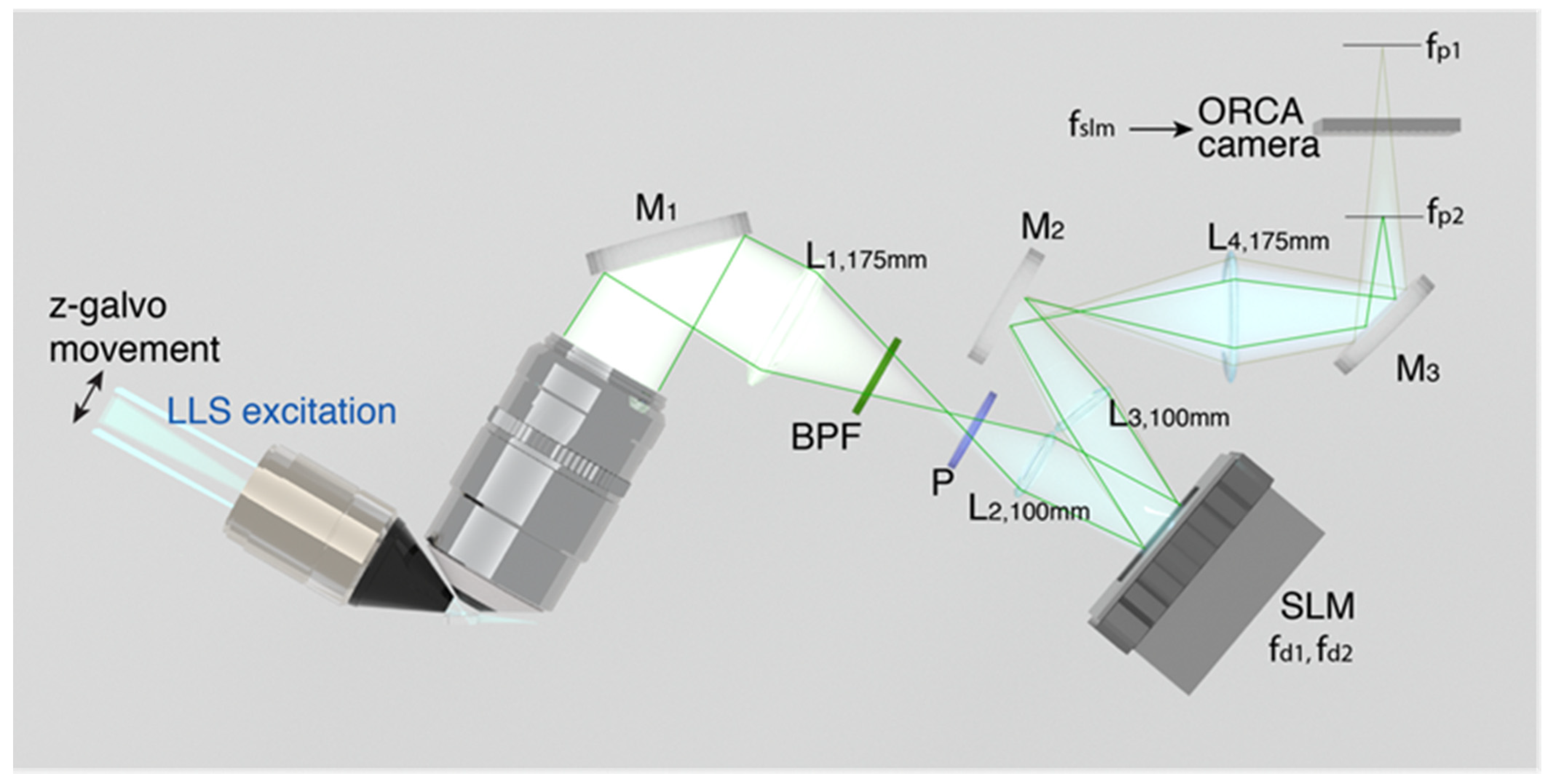
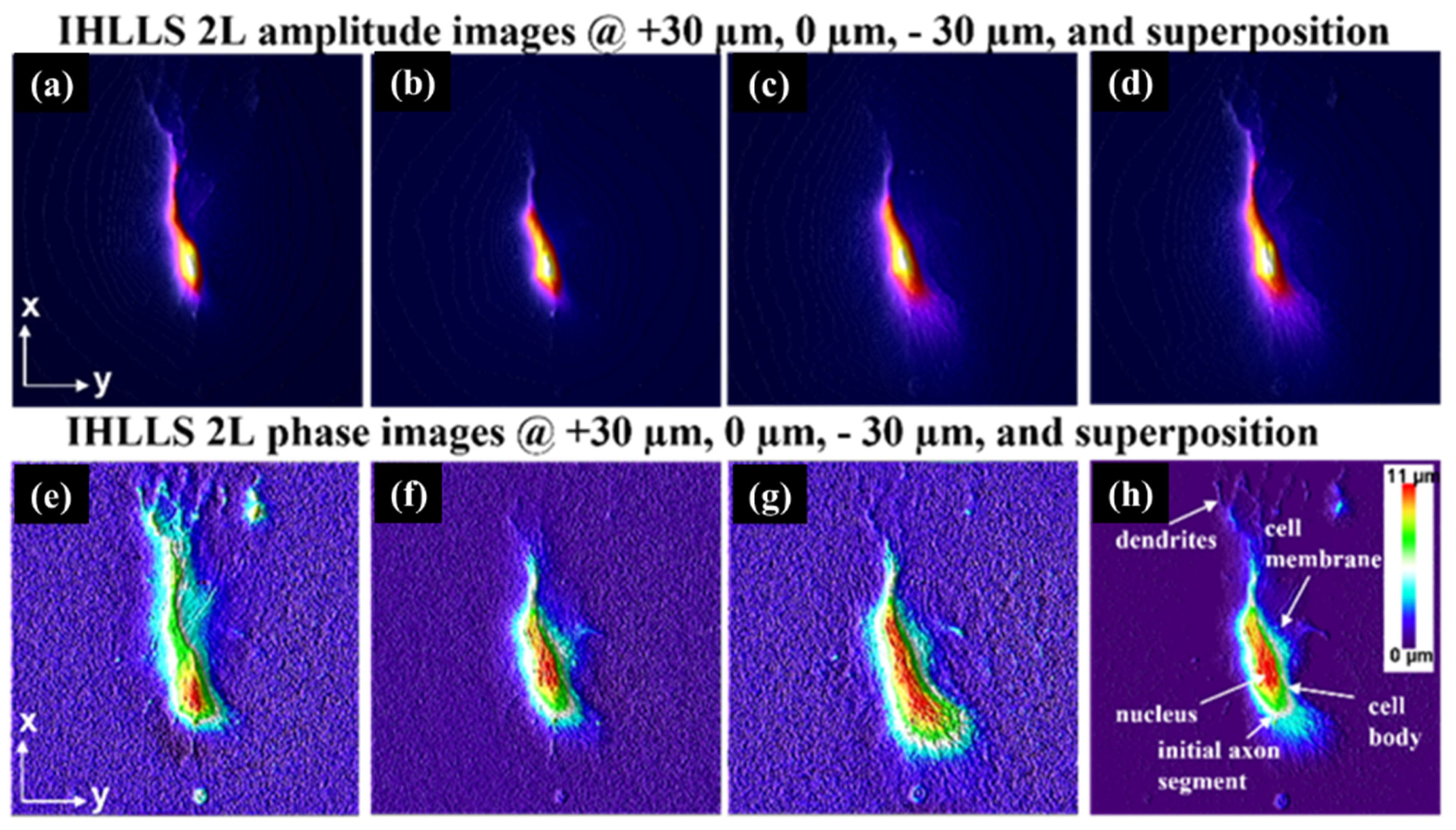
10. Incoherent Holography Lattice Light-Sheet (IHLLS) (Mariana Potcoava, Christopher Mann, Simon Alford and Jonathan Art)
10.1. Status
10.2. Current and Future Challenges
10.3. Advances in Science and Technology to Meet Challenges
10.4. Conclusions
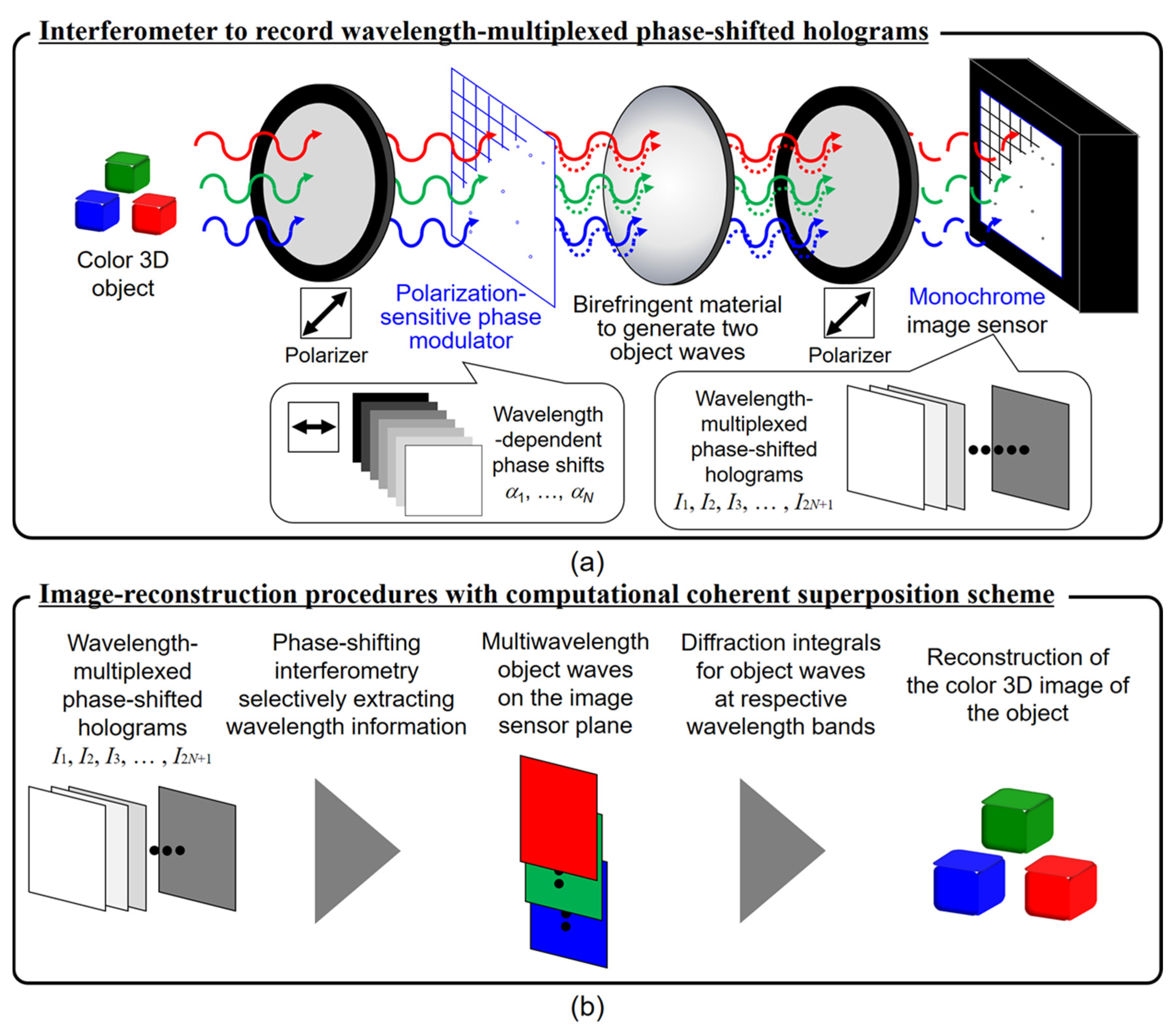
11. Multiwavelength-Multiplexed Incoherent Digital Holography Based on Computational Coherent Superposition (Tatsuki Tahara, Ayumi Ishii, Takako Koujin, Atsushi Matsuda, Yuichi Kozawa, and Ryutaro Oi)
11.1. Status
CCS-FINCH
11.2. Other Remarks and Conclusions
Author Contributions
Funding
Institutional Review Board Statement
Informed Consent Statement
Data Availability Statement
Acknowledgments
Conflicts of Interest
References
- Rosen, J.; Brooker, G. Digital spatially incoherent Fresnel holography. Opt. Lett. 2007, 32, 912–914. [Google Scholar] [CrossRef] [PubMed]
- Peters, P.J. Incoherent Holograms with Mercury Light Source. Appl. Phys. Lett. 1966, 8, 209. [Google Scholar] [CrossRef]
- Sirat, G.; Psaltis, D. Conoscopic holography. Opt. Lett. 1985, 10, 4–6. [Google Scholar] [CrossRef] [PubMed]
- Yamaguchi, I.; Zhang, T. Phase-shifting digital holography. Opt. Lett. 1997, 22, 1268–1270. [Google Scholar] [CrossRef] [PubMed]
- Poon, T.-C. Three-dimensional image processing and optical scanning holography. Adv. Imaging Electron Phys. 2003, 126, 329–350. [Google Scholar] [CrossRef]
- Abookasis, D.; Rosen, J. Three types of computer-generated hologram synthesized from multiple angular viewpoints of a three-dimensional scene. Appl. Opt. 2006, 45, 6533–6538. [Google Scholar] [CrossRef] [PubMed] [Green Version]
- Rosen, J.; Vijayakumar, A.; Kumar, M.; Rai, M.R.; Kelner, R.; Kashter, Y.; Bulbul, A.; Mukherjee, S. Recent advances in self-interference incoherent digital holography. Adv. Opt. Photon. 2019, 11, 1–66. [Google Scholar] [CrossRef]
- Rosen, J.; Kelner, R. Modified Lagrange invariants and their role in determining transverse and axial imaging resolutions of self-interference incoherent holographic systems. Opt. Express 2014, 22, 29048–29066. [Google Scholar] [CrossRef] [Green Version]
- Goodman, J. Introduction to Fourier Optics, 2nd ed.; McGraw-Hill: New York, NY, USA, 1996; Chapter 4; pp. 63–95. [Google Scholar]
- Brooker, G.; Siegel, N.; Wang, V.; Rosen, J. Optimal resolution in Fresnel incoherent correlation holographic fluorescence microscopy. Opt. Express 2011, 19, 5047–5062. [Google Scholar] [CrossRef] [Green Version]
- Kim, M.K. Adaptive optics by incoherent digital holography. Opt. Lett. 2012, 37, 2694–2696. [Google Scholar] [CrossRef]
- Nobukawa, T.; Katano, Y.; Goto, M.; Muroi, T.; Kinoshita, N.; Iguchi, Y.; Ishii, N. Incoherent digital holography simulation based on scalar diffraction theory. J. Opt. Soc. Am. A 2021, 38, 924–932. [Google Scholar] [CrossRef] [PubMed]
- Tahara, T.; Kanno, T.; Arai, Y.; Ozawa, T. Single-shot phase-shifting incoherent digital holography. J. Opt. 2017, 19, 065705. [Google Scholar] [CrossRef]
- Anand, V.; Katkus, T.; Lundgaard, S.; Linklater, D.P.; Ivanova, E.P.; Ng, S.H.; Juodkazis, S. Fresnel incoherent correlation holography with single camera shot. Opto-Electron. Adv. 2020, 3, 200004. [Google Scholar] [CrossRef]
- Wu, M.; Tang, M.; Zhang, Y.; Du, Y.; Ma, F.; Liang, E.; Gong, Q. Single-shot Fresnel incoherent correlation holography mi-croscopy with two-step phase-shifting. J. Mod. Opt. 2021, 68, 564–572. [Google Scholar] [CrossRef]
- Siegel, N.; Brooker, G. Single shot holographic super-resolution microscopy. Opt. Express 2021, 29, 15953–15968. [Google Scholar] [CrossRef]
- Rosen, J.; Brooker, G. Non-scanning motionless fluorescence three-dimensional holographic microscopy. Nat. Photon. 2008, 2, 190–195. [Google Scholar] [CrossRef]
- Brooker, G.; Siegel, N.; Rosen, J.; Hashimoto, N.; Kurihara, M.; Tanabe, A. In-line FINCH super resolution digital holo-graphic fluorescence microscopy using a high efficiency transmission liquid crystal GRIN lens. Opt. Lett. 2013, 38, 5264–5267. [Google Scholar] [CrossRef] [Green Version]
- Kelner, R.; Katz, B.; Rosen, J. Optical sectioning using a digital Fresnel incoherent-holography-based confocal imaging sys-tem. Optica 2014, 1, 70–74. [Google Scholar] [CrossRef] [Green Version]
- Siegel, N.; Brooker, G. Improved axial resolution of FINCH fluorescence microscopy when combined with spinning disk confocal microscopy. Opt. Express 2014, 22, 22298–22307. [Google Scholar] [CrossRef] [Green Version]
- Kashter, Y.; Rosen, J. Enhanced-resolution using modified configuration of Fresnel incoherent holographic recorder with synthetic aperture. Opt. Express 2014, 22, 20551–20565. [Google Scholar] [CrossRef] [Green Version]
- Kashter, Y.; Vijayakumar, A.; Miyamoto, Y.; Rosen, J. Enhanced super resolution using Fresnel incoherent correlation holography with structured illumination. Opt. Lett. 2016, 41, 1558–1561. [Google Scholar] [CrossRef] [PubMed]
- Kashter, Y.; Vijayakumar, A.; Rosen, J. Resolving images by blurring: Superresolution method with a scattering mask be-tween the observed objects and the hologram recorder. Optica 2017, 4, 932–939. [Google Scholar] [CrossRef]
- Rosen, J.; Brooker, G. Fluorescence incoherent color holography. Opt. Express 2007, 15, 2244–2250. [Google Scholar] [CrossRef] [Green Version]
- Kim, M.K. Full color natural light holographic camera. Opt. Express 2013, 21, 9636–9642. [Google Scholar] [CrossRef]
- Tahara, T.; Koujin, T.; Matsuda, A.; Ishii, A.; Ito, T.; Ichihashi, Y.; Oi, R. Incoherent color digital holography with computational coherent superposition for fluorescence imaging [Invited]. Appl. Opt. 2021, 60, A260–A267. [Google Scholar] [CrossRef]
- Kelner, R.; Rosen, J. Spatially incoherent single channel digital Fourier holography. Opt. Lett. 2012, 37, 3723–3725. [Google Scholar] [CrossRef] [Green Version]
- Kelner, R.; Rosen, J.; Brooker, G. Enhanced resolution in Fourier incoherent single channel holography (FISCH) with reduced optical path difference. Opt. Express 2013, 21, 20131–20144. [Google Scholar] [CrossRef]
- Vijayakumar, A.; Kashter, Y.; Kelner, R.; Rosen, J. Coded aperture correlation holography—A new type of incoherent digital holograms. Opt. Express 2016, 24, 12430–12441. [Google Scholar] [CrossRef]
- Bouchal, P.; Kapitán, J.; Chmelík, R.; Bouchal, Z. Point spread function and two-point resolution in Fresnel incoherent cor-relation holography. Opt. Express 2011, 19, 15603–15620. [Google Scholar] [CrossRef] [PubMed]
- Lai, X.; Zeng, S.; Lv, X.; Yuan, J.; Fu, L. Violation of the Lagrange invariant in an optical imaging system. Opt. Lett. 2013, 38, 1896–1898. [Google Scholar] [CrossRef] [PubMed]
- Katz, B.; Rosen, J.; Kelner, R.; Brooker, G. Enhanced resolution and throughput of Fresnel incoherent correlation holography (FINCH) using dual diffractive lenses on a spatial light modulator (SLM). Opt. Express 2012, 20, 9109–9121. [Google Scholar] [CrossRef] [PubMed] [Green Version]
- Nobukawa, T.; Muroi, T.; Katano, Y.; Kinoshita, N.; Ishii, N. Single-shot phase-shifting incoherent digital holography with multiplexed checkerboard phase gratings. Opt. Lett. 2018, 43, 1698–1701. [Google Scholar] [CrossRef] [PubMed]
- Sakamaki, S.; Yoneda, N.; Nomura, T. Single-shot in-line Fresnel incoherent holography using a dual-focus checkerboard lens. Appl. Opt. 2020, 59, 6612–6618. [Google Scholar] [CrossRef] [PubMed]
- Liang, D.; Zhang, Q.; Wang, J.; Liu, J. Single-shot Fresnel incoherent digital holography based on geometric phase lens. J. Mod. Opt. 2020, 67, 92–98. [Google Scholar] [CrossRef] [Green Version]
- Anand, V.; Katkus, T.; Ng, S.H.; Juodkazis, S. Review of Fresnel incoherent correlation holography with linear and non-linear correlations [Invited]. Chin. Opt. Lett. 2021, 19, 020501. [Google Scholar] [CrossRef]
- Zhou, H.; Huang, L.; Li, X.; Li, X.; Geng, G.; An, K.; Li, Z.; Wang, Y. All-dielectric bifocal isotropic metalens for single-shot hologram generation device. Opt. Express 2020, 28, 21549–21559. [Google Scholar] [CrossRef]
- Bouchal, P.; Bouchal, Z. Selective edge enhancement in three-dimensional vortex imaging with incoherent light. Opt. Lett. 2012, 37, 2949–2951. [Google Scholar] [CrossRef]
- Kim, N.; Alam, M.A.; Bang, L.T.; Phan, A.-H.; Piao, M.-L.; Erdenebat, M.-U. Advances in the light field displays based on integral imaging and holographic techniques (Invited Paper). Chin. Opt. Lett. 2014, 12, 60005–60009. [Google Scholar] [CrossRef]
- Marar, A.; Kner, P. Three-dimensional nanoscale localization of point-like objects using self-interference digital holography. Opt. Lett. 2020, 45, 591–594. [Google Scholar] [CrossRef]
- Potcoava, M.; Mann, C.; Art, J.; Alford, S. Spatio-temporal performance in an incoherent holography lattice light-sheet mi-croscope (IHLLS). Opt. Express 2021, 29, 23888–23901. [Google Scholar] [CrossRef]
- Tahara, T.; Ito, T.; Ichihashi, Y.; Oi, R. Multiwavelength three-dimensional microscopy with spatially incoherent light, based on computational coherent superposition. Opt. Lett. 2020, 45, 2482–2485. [Google Scholar] [CrossRef] [PubMed]
- Bouchal, P.; Bouchal, Z. Concept of coherence aperture and pathways toward white light hire-resolution correlation imaging. N. J. Phys. 2013, 15, 123002. [Google Scholar] [CrossRef] [Green Version]
- Nobukawa, T.; Katano, Y.; Goto, M.; Muroi, T.; Kinoshita, N.; Iguchi, Y.; Ishii, N. Coherence aperture restricted spatial reso-lution for an arbitrary depth plane in incoherent digital holography. Appl. Opt. 2021, 60, 5392–5398. [Google Scholar] [CrossRef] [PubMed]
- Nobukawa, T.; Katano, Y.; Muroi, T.; Kinoshita, N.; Ishii, N. Sampling requirements and adaptive spatial averaging for in-coherent digital holography. Opt. Express 2019, 27, 33634–33651. [Google Scholar] [CrossRef] [PubMed]
- Wan, Y.; Man, T.; Wu, F.; Kim, M.K.; Wang, D. Parallel phase-shifting self-interference digital holography with faithful re-construction using compressive sensing. Opt. Lasers Eng. 2016, 86, 38–43. [Google Scholar] [CrossRef] [Green Version]
- Quan, X.; Matoba, O.; Awatsuji, Y. Single-shot incoherent digital holography using a dual-focusing lens with diffraction gratings. Opt. Lett. 2017, 42, 383–386. [Google Scholar] [CrossRef] [PubMed]
- Nguyen, C.M.; Kwon, H.-S. Common-path off-axis incoherent Fourier holography with a maximum overlapping interference are. Opt. Lett. 2019, 44, 3406–3409. [Google Scholar] [CrossRef]
- Weng, J.; Clark, D.C.; Kim, M.K. Compressive sensing sectional imaging for single-shot in-line self-interference incoherent holography. Opt. Commun. 2016, 366, 88–93. [Google Scholar] [CrossRef]
- Choi, K.; Joo, K.-I.; Lee, T.-H.; Kim, H.-R.; Yim, J.; Do, H.; Min, S.-W. Compact self-interference incoherent digital holo-graphic camera system with real-time operation. Opt. Express 2019, 27, 4814–4833. [Google Scholar] [CrossRef]
- Zhang, Y.; Wu, M.-T.; Tang, M.-Y.; Ma, F.-Y.; Liang, E.-J.; Du, Y.-L.; Duan, Z.-Y.; Gong, Q.-X. Fresnel incoherent correlation hologram recording in real-time. Optik 2021, 241, 166938. [Google Scholar] [CrossRef]
- Hong, J.; Kim, M.K. Single-shot self-interference incoherent digital holography using off-axis configuration. Opt. Lett. 2013, 38, 5196–5199. [Google Scholar] [CrossRef] [PubMed]
- Indebetouw, G.; El Maghnouji, A.; Foster, R. Scanning holographic microscopy with transverse resolution exceeding the Rayleigh limit and extended depth of focus. J. Opt. Soc. Am. A 2005, 22, 892–898. [Google Scholar] [CrossRef] [PubMed] [Green Version]
- Zhu, Z.; Shi, Z. Self-interference polarization holographic imaging of a three-dimensional incoherent scene. Appl. Phys. Lett. 2016, 109, 091104. [Google Scholar] [CrossRef]
- Choi, K.; Yim, J.; Yoo, S.; Min, S.-W. Self-interference digital holography with a geometric-phase hologram lens. Opt. Lett. 2017, 42, 3940–3943. [Google Scholar] [CrossRef]
- Pancharatnam, S. Generalized theory of interference, and its applications. Proc. Math. Sci. 1956, 44, 247–262. [Google Scholar] [CrossRef]
- Awatsuji, Y.; Sasada, M.; Kubota, T. Parallel quasiphase-shifting digital holography. Appl. Phys. Lett. 2004, 85, 1069–1071. [Google Scholar] [CrossRef]
- Horner, J.L.; Gianino, P.D. Phase-only matched filtering. Appl. Opt. 1984, 23, 812–816. [Google Scholar] [CrossRef]
- Vijayakumar, A.; Kashter, Y.; Kelner, R.; Rosen, J. Coded aperture correlation holography system with improved performance [Invited]. Appl. Opt. 2017, 56, F67–F77. [Google Scholar] [CrossRef]
- Rai, M.; Vijayakumar, A.; Rosen, J. Non-linear adaptive three-dimensional imaging with interferenceless coded aperture correlation holography (I-COACH). Opt. Express 2018, 26, 18143–18154. [Google Scholar] [CrossRef]
- Anand, V.; Rosen, J.; Ng, S.; Katkus, T.; Linklater, D.; Ivanova, E.; Juodkazis, S. Edge and Contrast Enhancement Using Spatially Incoherent Correlation Holography Techniques. Photon 2021, 8, 224. [Google Scholar] [CrossRef]
- Tahara, T.; Kozawa, Y.; Ishii, A.; Wakunami, K.; Ichihashi, Y.; Oi, R. Two-step phase-shifting interferometry for self-interference digital holography. Opt. Lett. 2021, 46, 669–672. [Google Scholar] [CrossRef]
- Katz, B.; Wulich, D.; Rosen, J. Optimal noise suppression in Fresnel incoherent correlation holography (FINCH) configured for maximum imaging resolution. Appl. Opt. 2010, 49, 5757–5763. [Google Scholar] [CrossRef]
- Choi, K.-H.; Yim, J.; Min, S.-W. Optical defocus noise suppressing by using a pinhole-polarizer in Fresnel incoherent correlation holography. Appl. Opt. 2017, 56, F121–F127. [Google Scholar] [CrossRef] [PubMed]
- Rai, M.; Rosen, J. Noise suppression by controlling the sparsity of the point spread function in interferenceless coded aperture correlation holography (I-COACH). Opt. Express 2019, 27, 24311–24323. [Google Scholar] [CrossRef]
- Bulbul, A.; Rosen, J. Super-resolution imaging by optical incoherent synthetic aperture with one channel at a time. Photon. Res. 2021, 9, 1172. [Google Scholar] [CrossRef]
- Zhou, H.; Sain, B.; Wang, Y.; Schlickriede, C.; Zhao, R.; Zhang, X.; Wei, Q.; Li, X.; Huang, L.; Zentgraf, T. Polariza-tion-Encrypted Orbital Angular Momentum Multiplexed Metasurface Holography. ACS Nano 2020, 14, 5553–5559. [Google Scholar] [CrossRef] [PubMed]
- Yu, N.; Capasso, F. Flat optics with designer metasurfaces. Nat. Mater. 2014, 13, 139–150. [Google Scholar] [CrossRef]
- Ni, X.; Kildishev, A.; Shalaev, V.M. Metasurface holograms for visible light. Nat. Commun. 2013, 4, 2807. [Google Scholar] [CrossRef]
- Huang, L.; Chen, X.; Mühlenbernd, H.; Zhang, H.; Chen, S.; Bai, B.; Tan, Q.; Jin, G.; Cheah, K.W.; Qiu, C.-W.; et al. Three-dimensional optical holography using a plasmonic metasurface. Nat. Commun. 2013, 4, 2808. [Google Scholar] [CrossRef] [Green Version]
- Chen, W.T.; Zhu, A.Y.; Sanjeev, V.; Khorasaninejad, M.; Shi, Z.; Lee, E.; Capasso, F. A broadband achromatic metalens for focusing and imaging in the visible. Nat. Nanotechnol. 2018, 13, 220–226. [Google Scholar] [CrossRef] [Green Version]
- Wang, S.; Wu, P.C.; Su, V.-C.; Lai, Y.-C.; Chen, M.K.; Kuo, H.Y.; Chen, B.H.; Chen, Y.H.; Huang, T.-T.; Wang, J.-H.; et al. A broadband achromatic metalens in the visible. Nat. Nanotechnol. 2018, 13, 227–232. [Google Scholar] [CrossRef]
- Wei, Q.; Sain, B.; Wang, Y.; Reineke, B.; Li, X.; Huang, L.; Zentgraf, T. Simultaneous Spectral and Spatial Modulation for Color Printing and Holography Using All-Dielectric Metasurfaces. Nano Lett. 2019, 19, 8964–8971. [Google Scholar] [CrossRef] [PubMed] [Green Version]
- Jiang, Q.; Jin, G.; Cao, L. When metasurface meets hologram: Principle and advances. Adv. Opt. Photon. 2019, 11, 518–576. [Google Scholar] [CrossRef]
- Paniagua-Domínguez, R.; Yu, Y.F.; Khaidarov, E.; Choi, S.; Leong, V.; Bakker, R.M.; Liang, X.; Fu, Y.H.; Valuckas, V.; Krivitsky, L.A.; et al. A Metalens with a Near-Unity Numerical Aperture. Nano Lett. 2018, 18, 2124–2132. [Google Scholar] [CrossRef] [Green Version]
- Zang, X.; Ding, H.; Intaravanne, Y.; Chen, L.; Peng, Y.; Xie, J.; Ke, Q.; Balakin, A.V.; Shkurinov, A.P.; Chen, X.; et al. A Multi-Foci Metalens with Polarization-Rotated Focal Points. Laser Photon. Rev. 2019, 13, 1900182. [Google Scholar] [CrossRef]
- Chen, C.; Song, W.; Chen, J.-W.; Wang, J.-H.; Chen, Y.H.; Xu, B.; Chen, M.K.; Li, H.; Fang, B.; Chen, J.; et al. Spectral tomographic imaging with aplanatic metalens. Light. Sci. Appl. 2019, 8, 99. [Google Scholar] [CrossRef] [Green Version]
- Gao, S.; Park, C.; Zhou, C.; Lee, S.; Choi, D. Twofold Polarization-Selective All-Dielectric Trifoci Metalens for Linearly Polarized Visible Light. Adv. Opt. Mater. 2019, 7, 1900883. [Google Scholar] [CrossRef]
- Khorasaninejad, M.; Capasso, F. Metalenses: Versatile multifunctional photonic components. Science 2017, 358, eaam8100. [Google Scholar] [CrossRef] [PubMed] [Green Version]
- Roy, T.; Zhang, S.; Jung, I.W.; Troccoli, M.; Capasso, F.; Lopez, D. Dynamic metasurface lens based on MEMS technology. APL Photon. 2018, 3, 021302. [Google Scholar] [CrossRef]
- She, A.; Zhang, S.; Shian, S.; Clarke, D.R.; Capasso, F. Adaptive metalenses with simultaneous electrical control of focal length, astigmatism, and shift. Sci. Adv. 2018, 4, eaap9957. [Google Scholar] [CrossRef] [Green Version]
- Rosen, J.; Brooker, G. Fresnel incoherent correlation holography (FINCH)—A review of research. Adv. Opt. Technol. 2012, 1, 151. [Google Scholar] [CrossRef]
- Bouchal, P.; Bouchal, Z. Wide-field common-path incoherent correlation microscopy with a perfect overlapping of interfering beams. J. Eur. Opt. Soc. Rapid Publ. 2013, 8, 13011. [Google Scholar] [CrossRef] [Green Version]
- Siegel, N.; Lupashin, V.; Storrie, B.; Brooker, G. High-magnification super-resolution FINCH microscopy using birefringent crystal lens interferometers. Nat. Photon. 2016, 10, 802–808. [Google Scholar] [CrossRef] [PubMed] [Green Version]
- Rosen, J.; Siegel, N.; Brooker, G. Theoretical and experimental demonstration of resolution beyond the Rayleigh limit by FINCH fluorescence microscopic imaging. Opt. Express 2011, 19, 26249–26268. [Google Scholar] [CrossRef] [PubMed]
- Lee, H.-L.D.; Sahl, S.J.; Lew, M.; Moerner, W.E. The double-helix microscope super-resolves extended biological structures by localizing single blinking molecules in three dimensions with nanoscale precision. Appl. Phys. Lett. 2012, 100, 153701–1537013. [Google Scholar] [CrossRef] [Green Version]
- Fürhapter, S.; Jesacher, A.; Bernet, S.; Ritsch-Marte, M. Spiral phase contrast imaging in microscopy. Opt. Express 2005, 13, 689–694. [Google Scholar] [CrossRef] [Green Version]
- Fürhapter, S.; Jesacher, A.; Maurer, C.; Bernet, S.; Ritsch-Marte, M. Spiral Phase Microscopy. Adv. Imaging Electron Phys. 2007, 146, 56e–59e. [Google Scholar] [CrossRef]
- Bouchal, P.; Bouchal, Z. Flexible non-diffractive vortex microscope for three-dimensional depth-enhanced super-localization of dielectric, metal and fluorescent nanoparticles. J. Opt. 2017, 19, 105606. [Google Scholar] [CrossRef]
- Greengard, A.; Schechner, Y.Y.; Piestun, R. Depth from diffracted rotation. Opt. Lett. 2006, 31, 181–183. [Google Scholar] [CrossRef] [Green Version]
- Baránek, M.; Bouchal, P.; Šiler, M.; Bouchal, Z. Aberration resistant axial localization using a self-imaging of vortices. Opt. Express 2015, 23, 15316–15331. [Google Scholar] [CrossRef]
- Bouchal, P.; Bouchal, Z. Non-iterative holographic axial localization using complex amplitude of diffraction-free vortices. Opt. Express 2014, 22, 30200–30216. [Google Scholar] [CrossRef]
- Castejón, O.J. Confocal laser scanning microscope and immunohistochemistry of cerebellar Lugaro cells. Biocell 2013, 37, 29–36. [Google Scholar] [CrossRef]
- Denk, W.; Piston, D.; Webb, W. Multi-photon molecular excitation in laser-scanning microscope. In Handbook of Biological Confocal Microscope; Pawley, J.B., Ed.; Springer Science & Business Media: Berlin, Germany, 1995; pp. 535–549. [Google Scholar]
- Laperchia, C.; Mascaro, A.L.A.; Sacconi, L.; Andrioli, A.; Mattè, A.; Franceschi, L.D.; Grassi-Zucconi, G.; Bentivoglio, M.; Buffelli, M.; Pavone, F.S. Two-photon microscope imaging of thy1GFP-M transgenic mice: A novel animal model to investigate brain dendritic cell subsets in vivo. PLoS ONE 2013, 8, 005614. [Google Scholar] [CrossRef]
- Jun, C.; Cheol, K.; Hun, Y.; Ki, J.; Hun, S. Dual-wavelength digital holography microscope for BGA measurement using partial coherence sources. J. Opt. Soc. Korea 2011, 4, 352–356. [Google Scholar]
- Langecheneberg, P.; Kemper, B.; Dirksen, D. Autofocusing in digital holographic phase contrast microscope on pure phase objects for live cell imaging. Appl. Opt. 2008, 47, 176–182. [Google Scholar] [CrossRef] [PubMed]
- Mark, A.; David, W. High-contrast imaging of fluorescent protein FRET by fluorescence polarization microscope. Biophys. J. 2005, 88, 14–18. [Google Scholar]
- Toney, T.; Haro, P.; Sotillo, B.; Solis, J. Ion migration assisted inscription of high refractive index contrast waveguides by femtosecond laser pulses in phosphate glass. Opt. Lett. 2013, 38, 5248–5251. [Google Scholar] [CrossRef] [Green Version]
- Le, T.B.; Piao, M.; Jeong, J.-R.; Jeon, S.-H.; Kim, N. Improving Phase Contrast of Digital Holographic Microscope using Spatial Light Modulator. J. Opt. Soc. Korea 2015, 19, 22–28. [Google Scholar] [CrossRef] [Green Version]
- Ritter, G.; Veith, R.; Siebrasse, J.; Kobitscheck, U. High-contrast single-particle tracking by selective focal plane illumination microscope. Opt. Express 2008, 16, 7142–7152. [Google Scholar] [CrossRef]
- Patterson, G.; Davidson, M.; Manley, S.; Lippincott-Schwartz, J. Superresolution Imaging using Single-Molecule Localization. Ann. Rev. Phys. Chem. 2010, 61, 345–367. [Google Scholar] [CrossRef] [Green Version]
- Huang, B.; Wang, W.; Bates, M.; Zhuang, X. Three-dimensional super-resolution imaging by stochastic optical reconstruction microscopy. Science 2008, 319, 810–813. [Google Scholar] [CrossRef] [PubMed] [Green Version]
- Pavani, S.R.P.; Thompson, M.A.; Biteen, J.S.; Lord, S.J.; Liu, N.; Twieg, R.J.; Piestun, R.; Moerner, W.E. Three-dimensional, single-molecule fluorescence imaging beyond the diffraction limit by using a double-helix point spread function. Proc. Natl. Acad. Sci. USA 2009, 106, 2995–2999. [Google Scholar] [CrossRef] [Green Version]
- Shechtman, Y.; Weiss, L.; Backer, A.S.; Sahl, S.J.; Moerner, W.E. Precise Three-Dimensional Scan-Free Multiple-Particle Tracking over Large Axial Ranges with Tetrapod Point Spread Functions. Nano Lett. 2015, 15, 4194–4199. [Google Scholar] [CrossRef] [PubMed]
- Shechtman, Y.; Weiss, L.; Backer, A.S.; Lee, M.Y.; Moerner, W.E. Multicolour localization microscopy by point-spread-function engineering. Nat. Photon. 2016, 10, 590–594. [Google Scholar] [CrossRef] [PubMed]
- Bon, P.; Maucort, G.; Wattellier, B.; Monneret, S. Quadriwave lateral shearing interferometry for quantitative phase microscopy of living cells. Opt. Express 2009, 17, 13080–13094. [Google Scholar] [CrossRef] [PubMed]
- Bon, P.; Linarès-Loyez, J.; Feyeux, M.; Alessandri, K.; Lounis, B.; Nassoy, P.; Cognet, L. Self-interference 3D super-resolution microscopy for deep tissue investigations. Nat. Methods 2018, 15, 449–454. [Google Scholar] [CrossRef]
- Liebel, M.; Ortega Arroyo, J.; Beltrán, V.S.; Osmond, J.; Jo, A.; Lee, H.; Quidant, R.; van Hulst, N.F. 3D tracking of extracellular vesicles by holographic fluorescence imaging. Sci. Adv. 2020, 6, eabc2508. [Google Scholar] [CrossRef]
- Marar, A.; Kner, P. Fundamental precision bounds for three-dimensional optical localization microscopy using self-interference digital holography. Biomed. Opt. Express 2021, 12, 20–40. [Google Scholar] [CrossRef]
- Smith, C.S.; Joseph, N.; Rieger, B.; Lidke, K.A. Fast, single-molecule localization that achieves theoretically minimum uncertainty. Nat. Methods 2010, 7, 373–375. [Google Scholar] [CrossRef] [Green Version]
- Huang, F.; Schwartz, S.L.; Byars, J.M.; Lidke, K.A. Simultaneous multiple-emitter fitting for single molecule su-per-resolution imaging. Biomed. Opt. Express 2011, 2, 1377–1393. [Google Scholar] [CrossRef] [Green Version]
- Jang, C.; Clark, D.C.; Kim, J.; Lee, B.; Kim, M.K. Signal enhanced holographic fluorescence microscopy with guide-star reconstruction. Biomed. Opt. Express 2016, 7, 1271–1283. [Google Scholar] [CrossRef] [Green Version]
- Keller, P.J.; Ahrens, M.B. Visualizing Whole-Brain Activity and Development at the Single-Cell Level Using Light-Sheet Microscopy. Neuron 2015, 85, 462–483. [Google Scholar] [CrossRef] [Green Version]
- Ji, N.; Freeman, N.J.J.; Smith, S.L. Technologies for imaging neural activity in large volumes. Nat. Neurosci. 2016, 19, 1154–1164. [Google Scholar] [CrossRef] [Green Version]
- Gao, L.; Shao, L.; Chen, B.-C.; Betzig, E. 3D live fluorescence imaging of cellular dynamics using Bessel beam plane illumination microscopy. Nat. Prot. 2014, 9, 1083–1101. [Google Scholar] [CrossRef] [PubMed]
- Chen, B.-C.; Legant, W.R.; Wang, K.; Shao, L.; Milkie, D.E.; Davidson, M.W.; Janetopoulos, C.; Wu, X.S.; Hammer, J.A.; Liu, Z.; et al. Lattice light-sheet microscopy: Imaging molecules to embryos at high spatiotemporal resolution. Science 2014, 346, 1257998. [Google Scholar] [CrossRef] [PubMed] [Green Version]
- Gabor, D. A New Microscopic Principle. Nat. Cell Biol. 1948, 161, 777–778. [Google Scholar] [CrossRef] [PubMed]
- Goodman, J.W.; Lawrence, R.W. Digital image formation from electronically detected holograms. Appl. Phys. Lett. 1967, 11, 77–79. [Google Scholar] [CrossRef]
- Lohmann, A.W. Reconstruction of Vectorial Wavefronts. Appl. Opt. 1965, 4, 1667–1668. [Google Scholar] [CrossRef]
- Dändliker, R.; Thalmann, R.; Prongué, D. Two-wavelength laser interferometry using superheterodyne detection. Opt. Lett. 1988, 13, 339–341. [Google Scholar] [CrossRef] [PubMed]
- Tahara, T.; Mori, R.; Arai, Y.; Takaki, Y. Four-step phase-shifting digital holography simultaneously sensing du-al-wavelength information using a monochromatic image sensor. J. Opt. 2015, 17, 125707. [Google Scholar] [CrossRef]
- Tahara, T.; Mori, R.; Kikunaga, S.; Arai, Y.; Takaki, Y. Dual-wavelength phase-shifting digital holography selectively extracting wavelength information from wavelength-multiplexed holograms. Opt. Lett. 2015, 40, 2810–2813. [Google Scholar] [CrossRef]
- Tahara, T.; Otani, R.; Omae, K.; Gotohda, T.; Arai, Y.; Takaki, Y. Multiwavelength digital holography with wave-length-multiplexed holograms and arbitrary symmetric phase shifts. Opt. Express 2017, 25, 11157–11172. [Google Scholar] [CrossRef]
- Lohmann, A.W. Wavefront Reconstruction for Incoherent Objects. J. Opt. Soc. Am. 1965, 55, 1555_1–1556. [Google Scholar] [CrossRef]
- Schilling, B.W.; Poon, T.-C.; Indebetouw, G.; Storrie, B.; Shinoda, K.; Suzuki, Y.; Wu, M.H. Three-dimensional holographic fluorescence microscopy. Opt. Lett. 1997, 22, 1506–1508. [Google Scholar] [CrossRef] [PubMed] [Green Version]
- Zhu, B.; Ueda, K.-I. Real-time wavefront measurement based on diffraction grating holography. Opt. Commun. 2003, 225, 1–6. [Google Scholar] [CrossRef]
- Millerd, J.; Brock, N.; Hayes, J.; Morris, M.N.; Novak, M.; Wyant, J. Pixelated phase-mask dynamic interferometer. Proc. SPIE 2004, 5531, 304. [Google Scholar]
- Tahara, T.; Ishii, A.; Ito, T.; Ichihashi, Y.; Oi, R. Single-shot wavelength-multiplexed digital holography for 3D fluorescent microscopy and other imaging modalities. Appl. Phys. Lett. 2020, 117, 031102. [Google Scholar] [CrossRef]
- Hara, T.; Tahara, T.; Ichihashi, Y.; Oi, R.; Ito, T. Multiwavelength-multiplexed phase-shifting incoherent color digital holog-raphy. Opt. Express 2020, 28, 10078–10089. [Google Scholar] [CrossRef]
- Vijayakumar, A.; Rosen, J. Spectrum and space resolved 4D imaging by coded aperture correlation holography (COACH) with diffractive objective lens. Opt. Lett. 2017, 42, 947–950. [Google Scholar] [CrossRef]
- Tahara, T.; Ito, T.; Ichihashi, Y.; Oi, R. Single-shot incoherent color digital holographic microscopy system with static polar-ization-sensitive optical elements. J. Opt. 2020, 22, 105702. [Google Scholar] [CrossRef]
- Tahara, T.; Okamoto, R.; Ishii, A.; Ito, T.; Wakunami, K.; Ichihashi, Y.; Oi, R. Multidimensional digital holographic microscopy based on computational coherent superposition for coherent and incoherent light sensing. Proc. SPIE 2020, 11551, 115510M. [Google Scholar]
- Ueda, K.; Takuma, H. A Novel Spectrometric Technique based on Fourier Transformation of Transmission Signal of Faraday Rotator. Rev. Laser Eng. 1984, 12, 652–659. [Google Scholar] [CrossRef] [Green Version]
- Yoshimori, K. Interferometric spectral imaging for three-dimensional objects illuminated by a natural light source. J. Opt. Soc. Am. A 2001, 18, 765–770. [Google Scholar] [CrossRef]


Publisher’s Note: MDPI stays neutral with regard to jurisdictional claims in published maps and institutional affiliations. |
© 2021 by the authors. Licensee MDPI, Basel, Switzerland. This article is an open access article distributed under the terms and conditions of the Creative Commons Attribution (CC BY) license (https://creativecommons.org/licenses/by/4.0/).
Share and Cite
Rosen, J.; Alford, S.; Anand, V.; Art, J.; Bouchal, P.; Bouchal, Z.; Erdenebat, M.-U.; Huang, L.; Ishii, A.; Juodkazis, S.; et al. Roadmap on Recent Progress in FINCH Technology. J. Imaging 2021, 7, 197. https://doi.org/10.3390/jimaging7100197
Rosen J, Alford S, Anand V, Art J, Bouchal P, Bouchal Z, Erdenebat M-U, Huang L, Ishii A, Juodkazis S, et al. Roadmap on Recent Progress in FINCH Technology. Journal of Imaging. 2021; 7(10):197. https://doi.org/10.3390/jimaging7100197
Chicago/Turabian StyleRosen, Joseph, Simon Alford, Vijayakumar Anand, Jonathan Art, Petr Bouchal, Zdeněk Bouchal, Munkh-Uchral Erdenebat, Lingling Huang, Ayumi Ishii, Saulius Juodkazis, and et al. 2021. "Roadmap on Recent Progress in FINCH Technology" Journal of Imaging 7, no. 10: 197. https://doi.org/10.3390/jimaging7100197