
Cu(II)/Polydopamine-Modified Glass Fiber Separators for High-Performance Zinc-Ion Batteries

School of Chemistry and Materials Science, Jiangsu Normal University, Xuzhou 221116, China
*
Author to whom correspondence should be addressed.
Batteries 2023, 9(7), 387; https://doi.org/10.3390/batteries9070387
Submission received: 8 June 2023
/
Revised: 8 July 2023
/
Accepted: 15 July 2023
/
Published: 20 July 2023
(This article belongs to the Special Issue Zinc-Ion Batteries: Issues and Opportunities)
Abstract
:Much attention has been given to aqueous zinc-ion batteries (ZIBs) due to their features of inherent safety, environmental compatibility, low cost, and fantastic energy density. Nevertheless, chemical corrosion and dendrite growth occurring on Zn anodes during the charge–discharge process, which often cause surface passivation and short circuit of cells, seriously hindering the development of ZIBs. To solve these problems, a Cu(II) and polydopamine co-modified glass fiber (Cu(II)-PDA/GF) is designed as separator. On one hand, the modification of PDA enhances ionic conductivity and the water absorbing capability of a glass fiber separator due to the presence of functional groups. On the other hand, the pre-deposition of Cu on Zn anodes enables the uniform nucleation of Zn during the initial deposition process. Due to the synergistic effect, reversible zinc plating/striping is achieved in symmetric cells, which display a long lifecycle of over 1800 h at the current density of 1 mA cm−2 and with a fixed capacity of 1 mAh cm−2. Moreover, the assembled Zn//V2O5 cells using the Cu(II)-PDA/GF separator also demonstrate improved capacity retention. This study provides a simple and effective separator modification strategy for high-performance and reliable ZIBs, which are conducive to other metal-based energy storage devices.
1. Introduction
The excessive consumption of traditional fossil energy has aggravated the issues of energy shortage and environmental pollution. The exploitation and utilization of clean energy is severely limited by its defects of instability [1,2]. Therefore, developing reliable large-scale energy storage systems (ESSs) with the advantages of low cost, high energy density, and high security is of great importance [3,4]. In recent years, aqueous rechargeable batteries, such as monovalent (K, Na) and multivalent (Mg, Ca, Zn, Al) ion batteries, have attracted considerable attention due to the features of nonflammability and abundant natural reserves [5,6,7,8]. Among these battery systems, zinc-ion batteries (ZIBs) are considered to be a good choice among next-generation batteries due to their advantages of low redox potential (−0.76 V, vs. SHE) and the high theoretical capacity (820 mAh g−1) of Zn anodes [8].
Unfortunately, undesirable dendrite growth and uncontrolled side reactions occurring on Zn anodes could accelerate the failure of Zn metal batteries. During the initial plating process, the random nucleation on Zn surface causes the nonuniform distribution of the electric field and leads to vertical Zn growth on the protrusions that eventually leads to the formation of Zn dendrite [9], which may pierce the separator and cause short-circuiting of the cell. Moreover, hydrogen evolution causes exhaustion of electrolytes and chemical corrosion produces “dead Zn”; these problems accelerate the failure of the cells [10].
To overcome these problems, many strategies have been developed such as modifying the zinc anode [11,12,13,14,15,16,17], implanting electrolyte additives [18,19,20,21], and employing polymer- or hydrogel-based electrolytes [22,23,24,25,26]. So far, most studies have been focused on decoration of electrolytes and electrodes, while little research has focused on separators. As a crucial component of batteries, separators could regulate ion diffusion and optimize the electrochemical kinetics of batteries during the charge–discharge process, which could lead to dendrite-free Zn deposition. The common separators are glass fiber (GF) or filter paper (FP), both of which possess good compatibility with aqueous electrolytes, but they are chemically inactive. Therefore, separators are usually functionalized by chemically engineering or surface modification to improve the cycle stability of ZIBs. For example, Janus separators with good electrolyte wettability and high ionic conductivity can be realized by adding vertical graphene carpet [27] or Ti3C2TX MXene [28] to one side of a commercial GF separator to homogenize the interfacial electric field and promote Zn nucleation kinetics. Moreover, supramolecules with abundant polar groups [29] were also reported to prevent the accumulation of Zn2+ and suppress the Zn dendrite by modifying the GF separator. In addition, during zinc ion electrodeposition, the cellulose/GO composite separator (CG) [30] achieved an ultra-stable dendrite-free anode through crystal orientation regulation.
Inspired by above studies, we designed a multifunctional Cu(II) doped polydopamine-modified GF (Cu(II)-PDA/GF) separator for high-performance ZIBs. Figure 1 schematically illustrates the Zn plating process in the cells with pristine GF and Cu(II)-PDA/GF separators. As shown in Figure 1, inhomogeneous Zn nucleation takes place at the initial plating stage in the cell with a pristine GF separator, which further leads to the growth of disordered Zn dendrite due to the wild 2D Zn2+ diffusion at the electrode/electrolyte interface. The as-formed Zn dendrites are inclined to cause the failure and short-circuiting of cells. In contrast, the abundant zincophilic active sites (amino, imino, and hydroxyl) in the Cu(II)-PDA/GF separator could regulate the randomly scattered ion and result in a homogeneously distributed Zn2+ flux over the entire Zn anode, which, therefore, would induce uniform Zn plating and lessen the growth of the Zn dendrite. Moreover, the extraordinarily strong adhesion is expected to induce intimate interactions between electrodes and the GF separator and relieve the local surface tension of Zn metal [31]. Interestingly, numerous Cu2+ are encapsuled in the PDA modification layer via the metal–ligand band with the functional groups and could be preferentially deposited to form the metal Cu layer on the Zn anode, which also contributes to uniform Zn deposition due to its good affinity with Zn atoms [32,33,34]. Based on above features, a Cu(II)-PDA/GF separator enables a Zn metal symmetric cell with a long lifecycle of 1800 h at 1 mA cm−2 and with a specific capacity of 1 mAh cm−2. The Zn//V2O5 delivers a high capacity of 196.1 mAh g−1 even after 1000 cycles at 2 A g−1.
2. Materials and Methods
All the chemicals were used as purchased without purification. The metal foils were purchased from Shenzhen Kejing Star Technology Co., Ltd., Shenzhen , China The separator is Whatman glass fiber with a thickness of 0.675 mm and pore size of 2.7 μm. ZnSO4·7H2O, CuSO4·5H2O, C8H11NO2·HCl, and V2O5 were purchased from Sinopharm Chemical Reagent Co., Ltd., Shanghai, China.
2.1. Fabrication of the Cu(II)-PDA/GF Separator
The co-modification of the separator is realized by a simple soaking process. Firstly, the infiltrating solution was prepared. Typically, 1.2 g of Tris (pH = 8.5) and 0.4 g of dopamine hydrochloride (2 mg·mL−1) were dissolved in 200 mL of deionized water under vigorous stirring. Then, 0.25 g of CuSO4·5H2O and 0.4 mL of H2O2 (19.6 mmol·L−1) were added in the above solution and stirred for 10 min. Secondly, the GF separator was pre-wetted with absolute ethanol and then completely submerged in the as-prepared infiltrating solution for 40 min. Finally, the GF was extracted and washed with deionized water three times and dried in vacuum atmosphere at 50 °C for 12 h to obtain modified Cu(II)-PDA/GF separator.
2.2. Characterization
X-ray powder diffraction (XRD, Bruker-D8 Advance X-ray diffractometer, Cu Kα radiation), energy dispersive X-ray spectroscopy (EDS), and X-ray photoelectron spectroscopy (XPS, Thermo Fisher K-Alpha system) were performed for composition analysis. Scanning electron microscope (SEM, Hitachi SU-8010) was used for morphology detection.
2.3. Electrochemical Measurements
The CR2032 coin battery was assembled with 2 M ZnSO4 as electrolyte and GF or Cu(II)-PDA/GF as separator. The V2O5 cathode was prepared by mixing V2O5, conductive Super P, and polytetrafluoroethylene (PTFE) binder with a mass ratio of 7:2:1. Ethanol was used as the dispersant to form a paste, and then the paste was rolled into thin film and cut into pieces with a mass load of ~2.0 mg cm−2. The battery test system (LAND, CT2001A) was used to test the electrochemical performance of the battery. It was used for cyclic voltammetry (CV) and electrochemical impedance spectroscopy (EIS) tests on the CHI 660e electrochemical station.
3. Results and Discussion
Dopamine readily self-polymerizes into PDA nanopolymers via an oxidation process, which can be deposited on the surface of various substrates to form functional coatings due to the super non-covalent/covalent bonding capability of catechol and quinone moieties. Herein, PDA nanopolymers were self-assembled on the GF separator to regulate the zincophilic and ion transport properties by dipping the GF in a DA monomer solution with CuSO4/H2O2 as a trigger [35]. As shown in Figure 2a and Figure S1, after the infiltration process, the color of the GF separator changed from white to brown. SEM images shown in Figure 2a,b display that the modified Cu(II)-PDA/GF separator retained its original porous structure, which facilitated the fast and full infiltration of the electrolyte. High magnification SEM images further display that the surface of the GF separator is uniformly coated by polymeric PDA nanoparticles (Figure 2b). EDS mapping images also exhibit that the even distribution of elements Si, C, N, and Cu further confirms the successful coating of Cu(II) doped PDA on GF (Figure 2c).
To investigate the chemical environment of the coating layer, XPS of the freshly prepared Cu(II)-PDA/GF separator was carried out. As shown in Figure 2d, typical peaks of Cu 2p, O 1s, N 1s, C 1s, and Si 2p can be obviously observed from the XPS survey spectra, further verifying the successful modification of the GF separator. The peaks located at 283.9 eV, 285.2 eV, and 287.2 eV in the high-resolution XPS spectra of C1s can be indexed to the C-H, C-N/C-O, and C=O bonds, respectively (Figure 2e). And those located at 399.0 eV and 400.3 eV in the N 1s spectra corresponds to the =NR and R2N-H bonds, respectively (Figure 2f). Notably, the obvious signals of Cu 2p located at 953.0 eV, 933.4 eV, and 941.9 eV can be attributed to the 2p1/2, 2p3/2, and satellite peaks of Cu2+ (Figure 2g), indicating that Cu2+ is trapped in the PDA layer due to the complexation reaction between Cu2+ and catechol groups. The introduction of Cu2+ can promote the polymerization of PDA [36]. XPS O1s peaks at 533.4 eV, 532.1 eV, 531.2 eV and 530.1 eV correspond to O-H, C-O, C=O, and Cu-O, respectively, further indicating the doping of Cu(II) in the PDA coating layer (Figure 2h). Based on above analysis, it can be confirmed that the polymeric Cu(II)-PDA layer was successfully constructed on the GF separator. Ionic conductivity is an important indicator for the selection of a separator. EIS tests of the stainless steel//stainless steel cells were carried out to evaluate the ionic conductivity of a pristine GF separator and Cu(II)-PDA/GF separator. As shown in Figure S2, the bulk resistance Rb at the high frequency intercept of the Nyquist plot is 0.97 Ω for the Cu(II)-PDA/GF separator and 1.32 Ω for the pristine GF. The ionic conductivity was calculated to be 89.01 mS cm−1 and 65.82 mS cm−1 for Cu(II)-PDA/GF and pristine GF, respectively, indicating significantly improved ionic conductivity of the modified GF (Figure 2i).
To elucidate the effect of the Cu(II)-PDA/GF separator on the electrochemical behavior of a Zn anode, morphology evolution of the Zn anode during the deposition process at 1 mA cm−2 was characterized by SEM. As shown in Figure 3a, messy dendrite growth starts to occur on the Zn anode after only 10 min of deposition, and it becomes fiercer in the following stage in the cells using a pristine GF separator (Figure 3b,c). In contrast, during the whole deposition process in the cell using the Cu(II)-PDA/GF separator, the Zn anode maintained a smooth texture without any obvious bulky protuberance, demonstrating a superior effect on the inhibition of dendrite growth (Figure 3d–f). The effect may be attributed to the abundant functional groups on PDA, which could induce the transportation of Zn2+ at the electrode/electrolyte interface. Notably, the EDS mapping images (Figure S3) of the Zn anode after 10 min deposition presents an even distribution of elements Cu, C, N, O, and S, indicating that the Cu(II)-PDA modification layer endows the separator with good adhesion with the Zn anode.
XPS measurements of the Cu(II)-PDA/GF separator and Zn anode before and after 1 h deposition at the current density of 1 mA cm−2 in symmetric cells were carried out. As shown in Figure 3g, the intensity of Cu(II) in the Cu(II)-PDA/GF separator sharply decreased after the deposition process. Notably, metal Cu can be obviously detected on the surface of Zn foil, indicating that Cu(II) in the modification layer is transferred into Cu(0) and deposited on Zn anode during the deposition process. It is reported that metallic Cu has a strong Zn binding ability, and can effectively reduce the nucleation overpotential of zinc, thereby promoting uniform deposition of Zn2+, and significantly reducing the possibility of tiny protrusions growing into zinc dendrite [37,38] (Figure 3g). Therefore, it is believed that the resulting Cu(0) also contributed to the uniform Zn deposition in the cells using Cu(II)-PDA/GF separator.
The electrochemical window is affected by the electrochemical stability of water, which includes the hydrogen evolution reaction (HER) and the oxygen evolution reaction (OER) of water. The HER and OER of symmetric cells using different separators were measured by LSV. As shown in Figure S4, compared with a pristine GF separator, a Cu(II)-PDA/GF separator displays a wider potential window, indicating that the Cu(II)-PDA modification can effectively inhibit the hydrogen evolution and oxygen evolution reactions, which will be helpful for the inhibition of side reactions. SEM images of the Zn foil after 48 h immersion in the cells using different separators further demonstrate that the Cu(II)-PDA/GF separator inhibits the growth of by-products and suppresses side reactions (Figure S5). To further evaluate the corrosion current density, Tafel measurements were performed. As shown in Figure 3h, compared with pristine GF separator (1.1038 mA cm−2), the Cu(II)-PDA/GF separator displays much lower corrosion current density (0.4262 mA cm−2); this further indicates that the corrosion of the zinc anode becomes lower after assembling with the Cu(II)-PDA/GF separator.
To further evaluate the hydrophilic character of the separators, a simple water absorption test was carried out. As shown in Figure 3i and Table S1, the Cu(II)-PDA/GF separator has greater water absorption capacity than pristine GF separator, indicating improved affinity with the electrolyte. The Cu(II)-PDA/GF separator with good hydrophilicity and ionic conductivity is expected to guarantee convenient Zn2+ transportation of ZIBs during the charge/discharge process.
To further evaluate the practical application of the as-prepared Cu(II)-PDA/GF separator, CE tests were carried out in Cu//Zn cells. As shown in Figure 4a and Figure S6, the cells with the Cu(II)-PDA/GF separators display long lifecycles of more than 1200 h and high average CE of 99.62% and 99.81% at the current densities of 1 mA cm−2 and 2 mA cm−2, respectively. The cells employing pristine GF separator (Figure 4a) presented an average CE of 96.2% during the initial 150 h and the CE values fluctuated dramatically in the following cycles. The severe fluctuations mainly resulted from the growth of zinc dendrites, parasitic side reactions, and the recovery of “dead Zn” that broke away from the hydrated zinc hydroxide sulfate.
From the initial galvanostatic charge/discharge (GCD) curves of Cu//Zn cells, the nucleation overpotential for Zn deposition can be calculated. The lower nucleation overpotential of the cell indicated that the crystal nucleation barrier was smaller, which is favorable for the uniform deposition and exfoliation of zinc. Otherwise, during the nucleation process of the crystal, the nucleation overpotential is large, and the resistance becomes larger [10]. As shown in Figure 4b, the nucleation overpotential of the GF separator battery was 46.24 mV, which was higher than that of the Cu(II)-PDA modified glass fiber separator battery (32.15 mV), indicating that the Cu(II)-PDA/GF separator can promote the uniform deposition of zinc ions. The GCD curves of the Cu//Zn battery with the dopamine-modified separator at the 200th and 500th cycles are very consistent, and also very close to the GCD curve at the 50th cycle. The battery exhibited excellent reversibility with a low voltage difference of 28 mV (Figure 4c). However, when the blank separator was used, the overlap of the GCD curves was not very good, and at the same time, the voltage gap was comparatively large (Figure S7).
The lifecycle and overall voltage hysteresis of Zn//Zn symmetric cells with different separators using 2 M ZnSO4 as electrolyte was investigated. As shown in Figure 4d, the cell employing the Cu(II)-PDA/GF separator exhibits a constant voltage profile and delivers a favorable cycle life of 1800 h at the current density of 1 mA cm−2 and with a fixed capacity of 1 mAh cm−2, which is much stable than those using a pristine GF separator or a PDA/GF separator. Notably, the parallel tested cell with a pristine GF separator suffered a quick cell failure after only 95 h due to short-circuiting, which results when the GF separator is pierced by the unrestrained growth of dendrite. Enlarged GCD curves display the decreased voltage hysteresis for the cell with Cu(II)-PDA/GF separator, indicating improved ion transportation ability. The cells using Cu(II)-PDA/GF separator also delivered stable plating/striping of 430 h at an increased current density of 2 mA cm−2 and areal capacity of 2 mAh cm−2 (Figure S8) and 260 h at a higher current density of 4 mA cm−2 and 4 mAh cm−2 (Figure 4e), which were far superior to those using a pristine GF separator and a PDA/GF separator. To comprehensively evaluate the advantages of the as-prepared Cu(II)-PDA/GF separator, Table S2 shows a comparison of the electrochemical performance of the cells using this separator and the reported materials. It can be seen that the Cu(II)-PDA/GF separator enables a Zn anode with excellent stability.
The morphology evolution of the Zn anode after 50 cycles in the symmetric cells using a pristine GF separator and a Cu(II)-PDA/GF separator was characterized by SEM. As shown in Figure 5a,b, the cycled Zn anode of the cell with the modified separator presents a relatively flat surface without any obvious zinc dendrite, and the SEM images of the cross-section (Figure 5c) also showed a smooth surface without a passivation layer. The Zn anode in the cell using the pristine GF separator (Figure 5d,e) displayed serious zinc dendrite growth and the surface of Zn anode is full of vertically grown microsheets, which may pierce the separator. The SEM image of the cross-section (Figure 5f) also shows a non-uniform corrosion layer. Therefore, it is confirmed that the Cu(II)-PDA/GF separator could inhibit the dendrite growth and chemical corrosion effectively, which can also be confirmed by reduced Rct in the EIS tests. As shown in Figure 5g,h, Rct of the symmetric cells using the pristine GF separators increased from 468.7 to 1558.0 Ω after 50 cycles, which are much higher values than those (260.1 Ω, 730.5 Ω) using Cu(II)-PDA/GF separators, further indicating the serious passivation of the Zn anode using pristine GF separators. In order to obtain more phase information, the XRD patterns of the Zn anodes after 50 cycles in the cells with different separators were measured (Figure 5i). Obviously, characteristic peaks of Zn4SO4(OH)6·5H2O are visible in the XRD pattern of the Zn anode using the pristine GF separator [39], illustrating that side reactions easily take place on the Zn anode and produce massive by-products during cycling. In contrast, the peak intensity of by-produces is significantly decreased when using Cu(II)-PDA/GF separator, further illustrating that the modified GF separator could effectively prevent electrode passivation.
In order to evaluate the practical performance of the modified separator, Zn//V2O5 full cells were assembled to study the electrochemical performance. The CV curves of the cells with Cu(II)-PDA/GF separator shown in Figure 6a display two pairs of redox peaks at 0.82/1.04 V, and 0.58/0.79 V, which can be indexed to the stepwise Zn2+ intercalation/deintercalation behavior in V2O5 host [40]. After three cycles, it was found that the redox peaks overlap well, indicating the superior cycling reversibility of the full cells with a Cu(II)-PDA/GF separator.
Rate capabilities of the full cells are shown in Figure 6b. It can be seen that when the current density gradually increased from 0.2 to 0.5, 1, and 2 A g−1, the battery assembled with the Cu(II)-PDA/GF separator decreased from 281 to 276, 265.3, and 240.6 mAh g−1, respectively. In contrast, the battery assembled with the pristine GF separator (Figure 6b) maintained 213.7 mAh g−1 at 0.2 A g−1 and then dropped abruptly to 192.4 mAh g−1 at 2 A g−1. Notably, when the current density was returned from 2 to 0.2 A g−1, the battery with the Cu(II)-PDA/GF separator could provide 258.8 mAh g−1 at the 70th, which is much higher than that using a GF separator.
Cycling performance of the cells was tested with a constant current charge and a discharge density of 2 A g−1. As shown in Figure 6c, GCD curves display two pairs of reversible voltage platforms, which are consistent with the CV results. Figure 6d shows that the specific capacity is obviously increased in the initial cycles, which can be attributed to the gradual activation process of V2O5 cathode [41]. After 1000 cycles, the battery assembled with the Cu(II)-PDA/GF separator delivers a high capacity of 196.1 mAh g−1 at a current density of 2 A g−1, which is much higher than that assembled with pristine GF separator of 140.9 mAh g−1. Moreover, the CE value of the Cu(II)-PDA/GF separator remains steady and at nearly 100% even after long-term cycling, displaying a significant improvement of the full cell’s performance.
4. Conclusions
In summary, the PDA nanopolymer was self-assembled on the surface of the glass fiber using a self-polymerization process in order to obtain a Cu(II)-PDA co-modified GF separator. The introduction of PDA effectively improved the zincophile and ion transport of the GF separator due to the functional groups. Cu(II) doping in the PDA coating layer was preferentially deposited on a Zn anode to induce uniform Zn nucleation. Due to the synergistic effect, side reactions and dendrite growth of Zn anodes were effectively depressed. Electrochemical measurements demonstrated that the symmetric cells assembled with the Cu(II)-PDA/GF separator could cycle for more than 1800 h at the current density of 1.0 mA cm−2 and with the fixed capacity of 1.0 mAh cm−2. The Zn//V2O5 cells using the modified GF separator also delivered high specific capacity and good cycling stability of 196.1 mAh g−1 after 1000 cycles at 2.0 A g−1. This work provides a facile modification method for glass fibers with interfacial regulation effects for high-performance ZIBs, which can also be used on other metal-based batteries.
Supplementary Materials
The following supporting information can be downloaded at: https://www.mdpi.com/article/10.3390/batteries9070387/s1, Figure S1: (a,b) SEM images of pristine GF separator. Insert in (a) is the photo of pristine GF; Figure S2: EIS test of the stainless steel//stainless steel cells with different separators; Figure S3: EDS images of Zn foils after Zn deposition for 10 min at the current density of 1 mA cm−2 in the symmetric cells using Cu(II)-PDA/GF separator; Figure S4: Electrochemical stability windows of Zn//Ti cells with pristine GF and Cu(II)-PDA/GF separator. (a,b) LSV curves measured at a scan rate of 1 mV s−1; Figure S5: The SEM images of zinc foils after assembled with pristine GF separator (a–c) and Cu(II)-PDA/GF separator (d–f) for 48 h; Figure S6: Coulombic efficiency of Zn plating/stripping on Cu at the current density of 1 mA cm−2 with the fixed capacity of 1 mAh cm−2 in Cu//Zn cells with different separators; Figure S7: Voltage and capacity distribution of Cu//Zn cells with pristine GF separator; Figure S8: Cycling performance of the symmetrical cells with pristine GF and Cu(II)-PDA/GF separator at the current density of 2 mA cm−2 with the fixed capacity of 2 mAh cm−2; Table S1: Data for GF and Cu-PDA/GF separators obtained from electrolyte absorption experiments; Table S2: A comparative table of this result with other same or different separators based ZIBs performance. References [42,43,44,45,46,47,48,49,50,51,52] are cited in the supplementary materials.
Author Contributions
Conceptualization, Q.W.; methodology, F.M. and K.X.; investigation, F.M.; resources, F.M., S.W., C.Z. and X.L.; writing—original draft preparation, F.M.; writing—review and editing, Q.W.; supervision, Q.W.; funding acquisition, Q.W. All authors have read and agreed to the published version of the manuscript.
Funding
This work was supported by the Natural Science Foundation of Jiangsu Province (No. BK20211352), Natural Science Foundation of Jiangsu Education Committee of China (No. 22KJA430005).
Data Availability Statement
The data presented in this study are available on request from the corresponding author.
Conflicts of Interest
The authors declare no conflict of interest.
References
- Huang, Y.; Zhu, M.; Huang, Y.; Pei, Z.; Li, H.; Wang, Z.; Xue, Q.; Zhi, C. Multifunctional Energy Storage and Conversion Devices. Adv. Mater. 2016, 28, 8344–8364. [Google Scholar] [CrossRef] [PubMed]
- Li, C.; Jin, S.; Archer, L.A.; Nazar, L.F. Toward Practical Aqueous Zinc-Ion Batteries for Electrochemical Energy Storage. Joule 2022, 6, 1733–1738. [Google Scholar] [CrossRef]
- Du, W.; Ang, E.H.; Yang, Y.; Zhang, Y.; Ye, M.; Li, C.C. Challenges in the Material and Structural Design of Zinc Anode towards High-Performance Aqueous Zinc-Ion Batteries. Energy Environ. Sci. 2020, 13, 3330–3360. [Google Scholar] [CrossRef]
- Ray, A.; Saruhan, B. Application of Ionic Liquids for Batteries and Supercapacitors. Materials 2021, 14, 2942. [Google Scholar] [CrossRef]
- Pan, Z.; Liu, X.; Yang, J.; Li, X.; Liu, Z.; Loh, X.; Wang, J. Aqueous Rechargeable Multivalent Metal-Ion Batteries: Advances and Challenges. Adv. Energy Mater. 2021, 11, 2100608. [Google Scholar] [CrossRef]
- Bidhan, P.; Sachin, R.R.; Shoyebmohamad, F.S.; Mohd, U.; Ricardo, A.; Nelson, Y.D.; Emad, S.G.; Abu HS, R.; Harjot, S.G.; Tokeer, A. Regulated Electrochemical Performance of Manganese Oxide Cathode for Potassium-Ion Batteries: A Combined Experimental and First-Principles Density Functional Theory (DFT) Investigation. J. Colloid Interface Sci. 2023, 633, 886–896. [Google Scholar]
- Zong, Y.; He, H.; Wang, Y.; Wu, M.; Ren, X.; Bai, Z.; Wang, N.; Ning, X.; Dou, S.X. Functionalized Separator Strategies toward Advanced Aqueous Zinc-Ion Batteries. Adv. Energy Mater. 2023, 13, 2300403. [Google Scholar] [CrossRef]
- Bidhan, P.; Sachin, R.R.; Nelson, Y.D.; Shoyebmohamad, F.S.; Nitish, K.; Emad, S.G.; Abdullah, A.A.; Rajaram, S.M.; Sanjay, M.; Rahul, R.S. High Stability and Long Cycle Life of Rechargeable Sodium-Ion Battery Using Manganese Oxide Cathode: A Combined Density Functional Theory (DFT) and Experimental Study. ACS Appl. Mater. Interfaces 2021, 13, 11433–11441. [Google Scholar]
- Xu, L.; Meng, T.; Zheng, X.; Li, T.; Brozena, A.H.H.; Mao, Y.; Zhang, Q.; Clifford, B.C.; Rao, J.; Hu, L. Nanocellulose-Carboxymethylcellulose Electrolyte for Stable, High-Rate Zinc-Ion Batteries. Adv. Funct. Mater. 2023, 33, 2302098. [Google Scholar] [CrossRef]
- Zhou, W.; Chen, M.; Tian, Q.; Chen, J.; Xu, X.; Wong, C.-P. Cotton-Derived Cellulose Film as A Dendrite-Inhibiting Separator to Stabilize the Zinc Metal Anode of Aqueous Zinc Ion Batteries. Energy Stor. Mater. 2022, 44, 57–65. [Google Scholar] [CrossRef]
- Hopkins, B.J.; Sassin, M.B.; Chervin, C.N.; Desario, P.A.; Parker, J.F.; Long, J.W.; Rolison, D.R. Fabricating Architected Zinc Electrodes with Unprecedented Volumetric Capacity in Rechargeable Alkaline Cells. Energy Stor. Mater. 2020, 27, 370–376. [Google Scholar] [CrossRef]
- Wang, Y.; Liu, Y.; Wang, H.; Dou, S.; Gan, W.; Ci, L.; Huang, Y.; Yuan, Q. MOF-Based Ionic Sieve Interphase for Regulated Zn2+ Flux toward Dendrite-Free Aqueous Zinc-Ion Batteries. J. Mater. Chem. A 2022, 10, 366–4375. [Google Scholar] [CrossRef]
- Han, D.; Ma, T.; Sun, T.-J.; Zhang, W.-J.; Tao, Z.-L. Zinc Anode Protection Strategy for Aqueous Zinc-Ion Batteries. Chinese J. Inorg. Chem. 2022, 38, 185–197. [Google Scholar]
- Yu, Y.; Xu, W.; Liu, X.; Lu, X. Challenges and Strategies for Constructing Highly Reversible Zinc Anodes in Aqueous Zinc-Ion Batteries: Recent Progress and Future Perspectives. Adv. Sustain. Syst. 2020, 4, 2000082. [Google Scholar] [CrossRef]
- Zhang, Q.; Luan, J.; Tang, Y.; Ji, X.; Wang, H. Interfacial Design of Dendrite-Free Zinc Anodes for Aqueous Zinc-Ion Batteries. Angew. Chem. Int. Ed. 2020, 59, 13180–13191. [Google Scholar] [CrossRef] [PubMed]
- Han, C.; Li, W.; Liu, H.K.; Dou, S.; Wang, J. Principals and Strategies for Constructing A Highly Reversible Zinc Metal Anode in Aqueous Batteries. Nano Energy 2020, 74, 104880. [Google Scholar] [CrossRef]
- Yi, Z.; Chen, G.; Hou, F.; Wang, L.; Liang, J. Strategies for the Stabilization of Zn Metal Anodes for Zn-Ion Batteries. Adv. Energy Mater. 2021, 11, 2003065. [Google Scholar] [CrossRef]
- Guo, X.; Zhang, Z.; Li, J.; Luo, N.; Chai, G.-L.; Miller, T.S.; Lai, F.; Shearing, P.; Brett, D.J.L.; Han, D.; et al. Alleviation of Dendrite Formation on Zinc Anodes via Electrolyte Additives. ACS Energy Lett. 2021, 6, 395–403. [Google Scholar] [CrossRef]
- Du, Y.; Li, Y.; Xu, B.B.; Liu, T.X.; Liu, X.; Ma, F.; Gu, X.; Lai, C. Electrolyte Salts and Additives Regulation Enables High Performance Aqueous Zinc Ion Batteries: A Mini Review. Small 2021, 18, 2104640. [Google Scholar] [CrossRef]
- Wu, M.; Zhang, Y.; Xu, L.; Yang, C.; Hong, M.; Cui, M.; Clifford, B.C.; He, S.; Jing, S.; Yao, Y.; et al. A Sustainable Chitosan-Zinc Electrolyte for High-Rate Zinc-Metal Batteries. Matter 2022, 5, 3402–3416. [Google Scholar] [CrossRef]
- Guo, S.; Qin, L.; Zhang, T.; Zhou, M.; Zhou, J.; Fang, G.; Liang, S. Fundamentals and Perspectives of Electrolyte Additives for Aqueous zinc-Ion Batteries. Energy Stor. Mater. 2021, 34, 545–562. [Google Scholar] [CrossRef]
- Wu, K.; Huang, J.; Yi, J.; Liu, X.; Liu, Y.; Wang, Y.; Zhang, J.; Xia, Y. Recent Advances in Polymer Electrolytes for Zinc Ion Batteries: Mechanisms, Properties, and Perspectives. Adv. Energy Mater. 2020, 10, 1903977. [Google Scholar] [CrossRef]
- Lu, K.; Jiang, T.; Hu, H.; Wu, M. Hydrogel Electrolytes for Quasi-Solid Zinc-Based Batteries. Front. Chem. 2020, 8, 546728. [Google Scholar] [CrossRef] [PubMed]
- Li, X.; Wang, D.; Ran, F. Key Approaches and Challenges in Fabricating Advanced Flexible Zinc-Ion Batteries with Functional Hydrogel Electrolytes. Energy Stor. Mater. 2023, 56, 351–393. [Google Scholar] [CrossRef]
- Dong, H.; Li, J.; Guo, J.; Lai, F.; Zhao, F.; Jiao, Y.; Brett, D.J.L.; Liu, T.; He, G.; Parkin, I.P. Insights on Flexible Zinc-Ion Batteries from Lab Research to Commercialization. Adv. Mater. 2021, 33, 2007548. [Google Scholar] [CrossRef]
- Liu, D.; Tang, Z.; Luo, L.; Yang, W.; Liu, Y.; Shen, Z.; Fan, X.-H. Self-Healing Solid Polymer Electrolyte with High Ion Conductivity and Super Stretchability for All-Solid Zinc-Ion Batteries. ACS Appl. Mater. Interfaces 2021, 13, 36320–36329. [Google Scholar] [CrossRef]
- Li, C.; Sun, Z.; Yang, T.; Yu, L.; Wei, N.; Tian, Z.; Cai, J.; Lv, J.; Shao, Y.; Rummeli, M.H.; et al. Directly Grown Vertical Graphene Carpets as Janus Separators toward Stabilized Zn Metal Anodes. Adv. Mater. 2020, 32, 2003425. [Google Scholar] [CrossRef]
- Su, Y.; Liu, B.; Zhang, Q.; Peng, J.; Wei, C.; Li, S.; Li, W.; Xue, Z.; Yang, X.; Sun, J. Printing-Scalable Ti3C2TX MXene-Decorated Janus Separator with Expedited Zn2+ Flux toward Stabilized Zn Anodes. Adv. Funct. Mater. 2022, 32, 2204306. [Google Scholar] [CrossRef]
- Liu, T.; Hong, J.; Wang, J.; Xu, Y.; Wang, Y. Uniform Distribution of Zinc Ions Achieved by Functional Supramolecules for Stable Zinc Metal Anode with Long Cycling Lifespan. Energy Stor. Mater. 2022, 45, 1074–1083. [Google Scholar] [CrossRef]
- Cao, J.; Zhang, D.; Gu, C.; Wang, X.; Wang, S.; Zhang, X.; Qin, J.; Wu, Z.-S. Manipulating Crystallographic Orientation of Zinc Deposition for Dendrite-free Zinc Ion Batteries. Adv. Energy Mater. 2021, 11, 2101299. [Google Scholar] [CrossRef]
- Ryou, M.-H.; Lee, D.J.; Lee, J.-N.; Lee, Y.M.; Park, J.-K.; Choi, J.W. Excellent Cycle Life of Lithium-Metal Anodes in Lithium-Ion Batteries with Mussel-Inspired Polydopamine-Coated Separators. Adv. Energy Mater. 2012, 2, 645–650. [Google Scholar] [CrossRef]
- Dong, Q.; Zhang, X.; Qian, J.; He, S.; Mao, Y.; Brozena, A.H.; Zhang, Y.; Pollard, T.P.; Borodin, O.A.; Wang, Y.; et al. A Cellulose-Derived Supramolecule for Fast Ion Transport. Sci. Adv. 2022, 8, eadd2031. [Google Scholar] [CrossRef] [PubMed]
- Qian, Y.; Meng, C.; He, J.; Dong, X. A Lightweight 3D Zn@Cu Nanosheets@Activated Carbon Cloth as Long-Life Anode with Large Capacity for Flexible Zinc Ion Batteries. J. Power Sources 2020, 480, 228871. [Google Scholar] [CrossRef]
- Li, C.; Shi, X.; Liang, S.; Ma, X.; Han, M.; Wu, X.; Zhou, J. Spatially Homogeneous Copper Foam as Surface Dendrite-Free Host for Zinc Metal Anode. Chem. Eng. J. 2020, 379, 122248. [Google Scholar] [CrossRef]
- Zhang, C.; Ou, Y.; Lei, W.-X.; Wan, L.-S.; Ji, J.; Xu, Z.-K. CuSO4/H2O2-Induced Rapid Deposition of Polydopamine Coatings with High Uniformity and Enhanced Stability. Angew. Chem. Int. Ed. 2016, 55, 3054–3057. [Google Scholar] [CrossRef]
- Yu, F.; Chen, S.; Chen, Y.; Li, H.; Yang, L.; Chen, Y.; Yin, Y. Experimental and Theoretical Analysis of Polymerization Reaction Process on the Polydopamine Membranes and Its Corrosion Protection Properties for 304 Stainless Steel. J. Mol. Struct. 2010, 982, 152–161. [Google Scholar] [CrossRef]
- Zeng, Y.; Sun, P.X.; Pei, Z.; Jin, Q.; Zhang, X.; Yu, L.; Lou, X.W. Nitrogen-Doped Carbon Fibers Embedded with Zincophilic Cu Nanoboxes for Stable Zn-Metal Anodes. Adv. Mater. 2022, 34, 2200342. [Google Scholar] [CrossRef]
- Xie, S.; Li, Y.; Li, X.; Zhou, Y.; Dang, Z.; Rong, J.; Dong, L. Stable Zinc Anodes Enabled by Zincophilic Cu Nanowire Networks. Nano-Micro Lett. 2022, 14, 39. [Google Scholar] [CrossRef]
- Lu, H.; Zhang, X.; Luo, M.; Cao, K.; Lu, Y.; Xu, B.B.; Pan, H.; Tao, K.; Jiang, Y. Amino Acid-Induced Interface Charge Engineering Enables Highly Reversible Zn Anode. Adv. Funct. Mater. 2021, 31, 2103514. [Google Scholar] [CrossRef]
- Wang, T.; Li, S.; Weng, X.; Gao, L.; Yan, Y.; Zhang, N.; Qu, X.; Jiao, L.; Liu, Y. Ultrafast 3D Hybrid-Ion Transport in Porous V2O5 Cathodes For Superior-Rate Rechargeable Aqueous Zinc Batteries. Adv. Energy Mater. 2023, 13, 2204358. [Google Scholar] [CrossRef]
- Zhang, Y.; Li, Z.; Gong, L.; Wang, X.; Hu, P.; Liu, J. Rational Construction of Ag@MIL-88B(V)-Derived Hierarchical Porous Ag-V2O5 Heterostructures with Enhanced Diffusion Kinetics and Cycling Stability for Aqueous Zinc-Ion Batteries. J. Energy Chem. 2023, 77, 561–571. [Google Scholar] [CrossRef]
- Liu, Y.; Liu, S.; Xie, X.; Li, Z.; Wang, P.; Lu, B.; Liang, S.; Tang, Y.; Zhou, J. A Functionalized Separator Enables Dendrite-Free Zn Anode via Metal-Polydopamine Coordination Chemistry. Infomat 2023, 5, e12374. [Google Scholar] [CrossRef]
- Guo, G.; Tan, X.; Wang, K.; Zheng, L.; Zhang, H. Regulating Zinc Deposition Behaviors by Functional Cotton Textiles as Separators for Aqueous Zinc-Metal Batteries. J. Power Sources 2023, 553, 232321. [Google Scholar] [CrossRef]
- Li, L.; Peng, J.; Jia, X.; Zhu, X.; Meng, B.; Yang, K.; Chu, D.; Yang, N.; Yu, J. PBC@Cellulose-Filter Paper Separator Design with Efficient Ion Transport Properties toward Stabilized Zinc-Ion Battery. Electrochim. Acta 2022, 430, 141129. [Google Scholar] [CrossRef]
- Qin, H.; Chen, W.; Kuang, W.; Hu, N.; Zhang, X.; Weng, H.; Tang, H.; Huang, D.; Xu, J.; He, H. A Nature-Inspired Separator with Water-Confined and Kinetics-Boosted Effects for Sustainable and High-Utilization Zn Metal Batteries. Small 2023, 19, 2300130. [Google Scholar] [CrossRef]
- Yang, X.; Li, W.; Lv, J.; Sun, G.; Shi, Z.; Su, Y.; Lian, X.; Shao, Y.; Zhi, A.; Tian, X.; et al. In Situ Separator Modification via CVD-Derived N-doped Carbon for Highly Reversible Zn Metal Anodes. Nano Res. 2022, 15, 9785–9791. [Google Scholar] [CrossRef]
- Ge, X.; Zhang, W.; Song, F.; Xie, B.; Li, J.; Wang, J.; Wang, X.; Zhao, J.; Cui, G. Single-Ion-Functionalized Nanocellulose Membranes Enable Lean-Electrolyte and Deeply Cycled Aqueous Zinc-Metal Batteries. Adv. Funct. Mater. 2022, 32, 2200429. [Google Scholar] [CrossRef]
- Li, Y.; Peng, X.; Li, X.; Duan, H.; Xie, S.; Dong, L.; Kang, F. Functional Ultrathin Separators Proactively Stabilizing Zinc Anodes for Zinc-Based Energy Storage. Adv. Mater. 2023, 35, 2300019. [Google Scholar] [CrossRef]
- Zhu, J.; Bie, Z.; Cai, X.; Jiao, Z.; Wang, Z.; Tao, J.; Song, W.; Fan, H.J. A Molecular-Sieve Electrolyte Membrane enables Separator-Free Zinc Batteries with Ultra long Cycle Life. Adv. Mater. 2022, 34, 2207209. [Google Scholar] [CrossRef]
- Yang, Y.; Chen, T.; Yu, B.; Zhu, M.; Meng, F.; Shi, W.; Zhang, M.; Qi, Z.; Zeng, K.; Xue, J. Manipulating Zn-ion Flux by Two-Dimensional Porous g-C3N4 Nanosheets for Dendrite-Free Zinc Metal Anode. Chem. Eng. J. 2022, 433, 134077. [Google Scholar] [CrossRef]
- Wu, B.; Wu, Y.; Lu, Z.; Zhang, J.; Han, N.; Wang, Y.; Li, X.-M.; Lin, M.; Zeng, L. A Cation Selective Separator Induced Cathode Protective Layer and Regulated Zinc Deposition for Zinc Ion Batteries. J. Mater. Chem. A 2021, 9, 4734–4743. [Google Scholar] [CrossRef]
- Song, Y.; Ruan, P.; Mao, C.; Chang, Y.; Wang, L.; Dai, L.; Zhou, P.; Lu, B.; Zhou, J.; He, Z. Metal-Organic Frameworks Functionalized Separators for Robust Aqueous Zinc-Ion Batteries. Nano-Micro Lett. 2022, 74, 104880. [Google Scholar] [CrossRef] [PubMed]
Figure 1.
Schematics of Zn deposition with pristine GF separator and Cu(II)-PDA/GF separator.
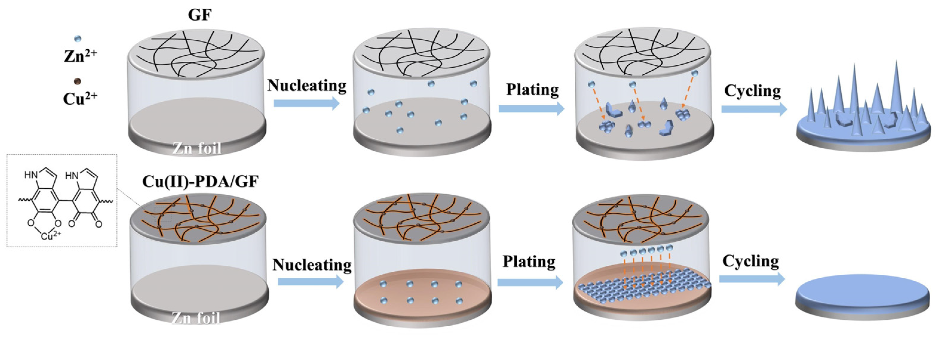
Figure 2.
(a,b) SEM images of Cu(II)-PDA/GF separator; insert in (a) is the photo of Cu(II)-PDA/GF separator. (c) EDS images of Cu(II)-PDA/GF separator. XPS survey spectra of Cu(II)-PDA/GF separator: (d) full survey XPS spectra; high-resolution XPS spectra of (e) C 1s, (f) N 1s, (g) Cu 2p, and (h) O 1s. (i) Ionic conductivity of pristine GF separator and Cu(II)-PDA/GF separator.

Figure 3.
The SEM images of zinc foils after zinc deposition for 10, 30, and 60 min at 1 mA cm−2: (a–c) in pristine GF separator cell; (d–f) in Cu(II)-PDA/GF separator cell. (g) XPS survey spectra of Cu(II)-PDA/GF separator; Cu(II)-PDA/GF separator after Zn deposition 1 h. (h) Linear polarization curves in pristine GF separator and Cu(II)-PDA/GF separator. (i) Electrolyte absorption of pristine GF separator and Cu(II)-PDA/GF separator with 2 M ZnSO4.
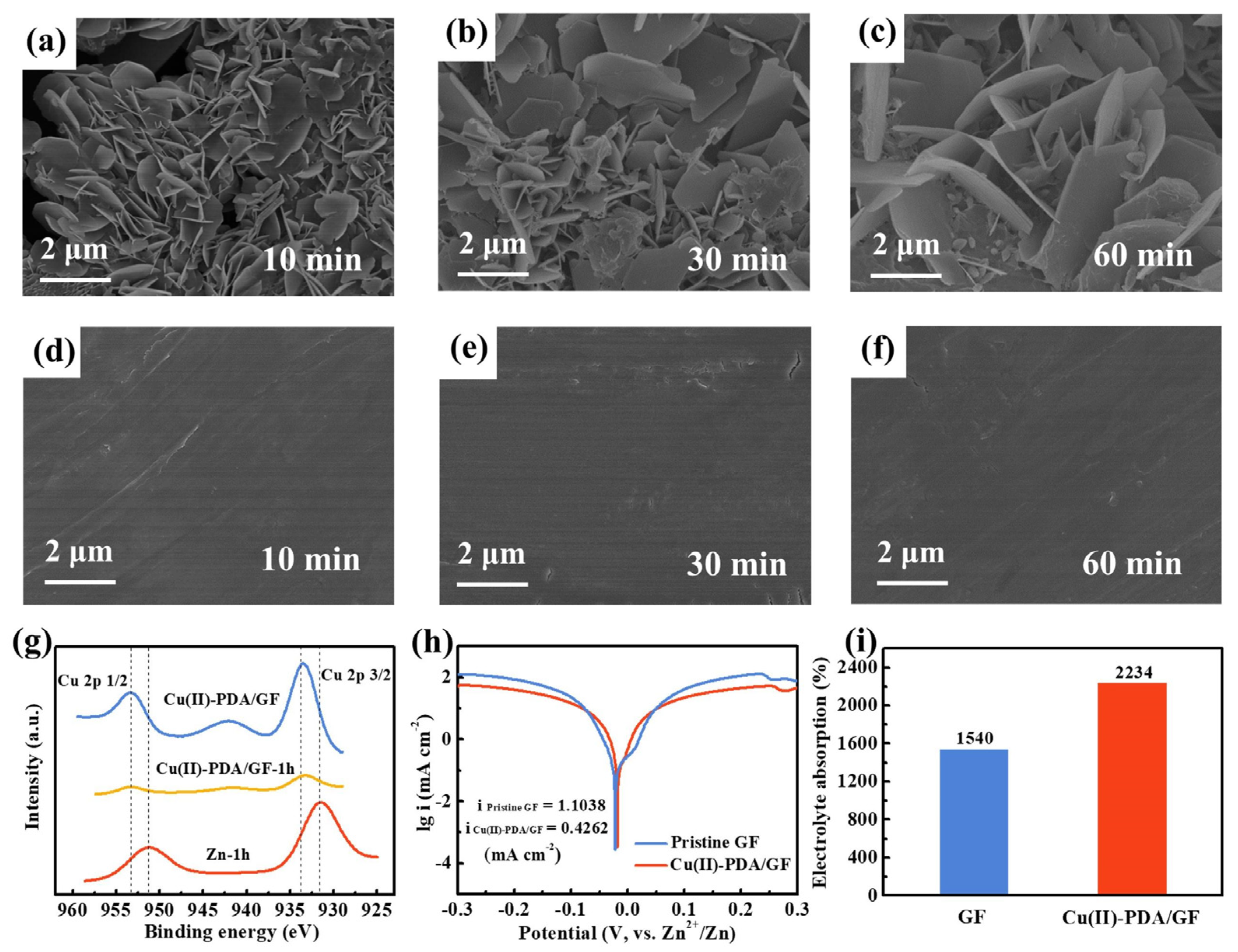
Figure 4.
(a) Columbic efficiency of Zn plating/stripping on Cu foil at the current density of 1 mA cm−2 with the fixed capacity of 1 mAh cm−2. (b) Voltage-capacity profiles of Cu//Zn cells with pristine GF separator and Cu(II)-PDA/GF separator (nucleation overpotential values are shown in the inset). (c) Voltage and capacity distribution of Cu//Zn cells with Cu(II)-PDA/GF separator assembled for different cycles. Cycling performance in symmetrical cells with pristine GF separator and Cu(II)-PDA/GF separator at the current density of (d) 1 mA cm−2 and (e) 4 mA cm−2.
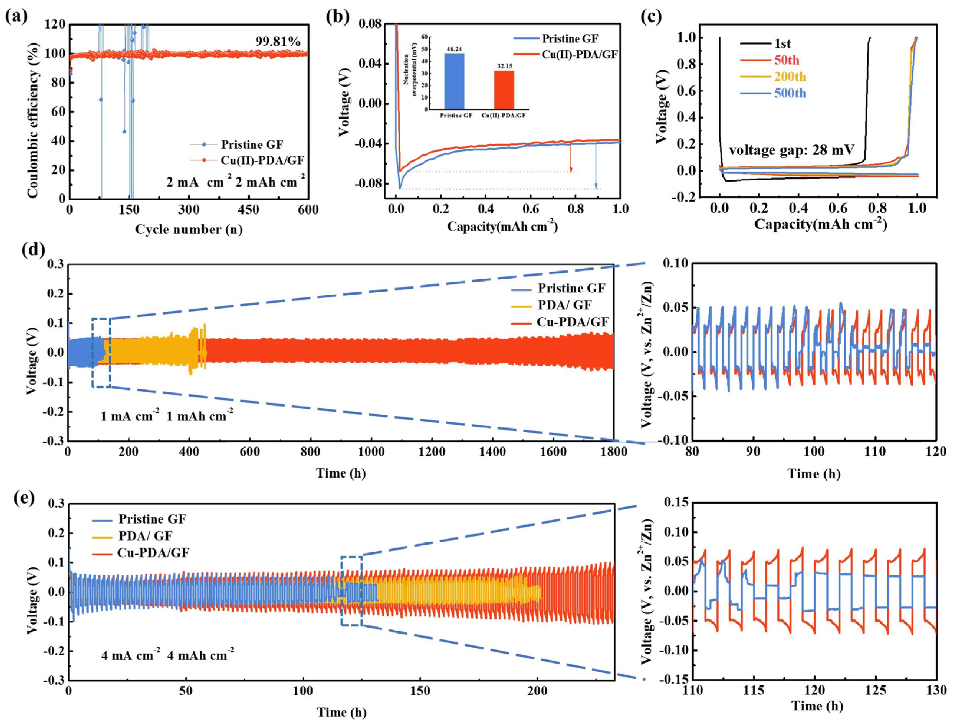
Figure 5.
Surface morphology and cross-sectional SEM images of the Zn anode after 50 cycles at 1 mA cm−2 and 1 mAh cm−2 in the cells using (a–c) Cu(II)-PDA/GF separator and (d–f) pristine GF separator. The EIS spectra and fitting results of the symmetric cells using different separators (g) before cycling and (h) after 50 cycles. (i) XRD patterns of the Zn anode after 50 cycles at 1 mA cm−2 and 1 mAh cm−2 with pristine GF separator and Cu(II)-PDA/GF separator.
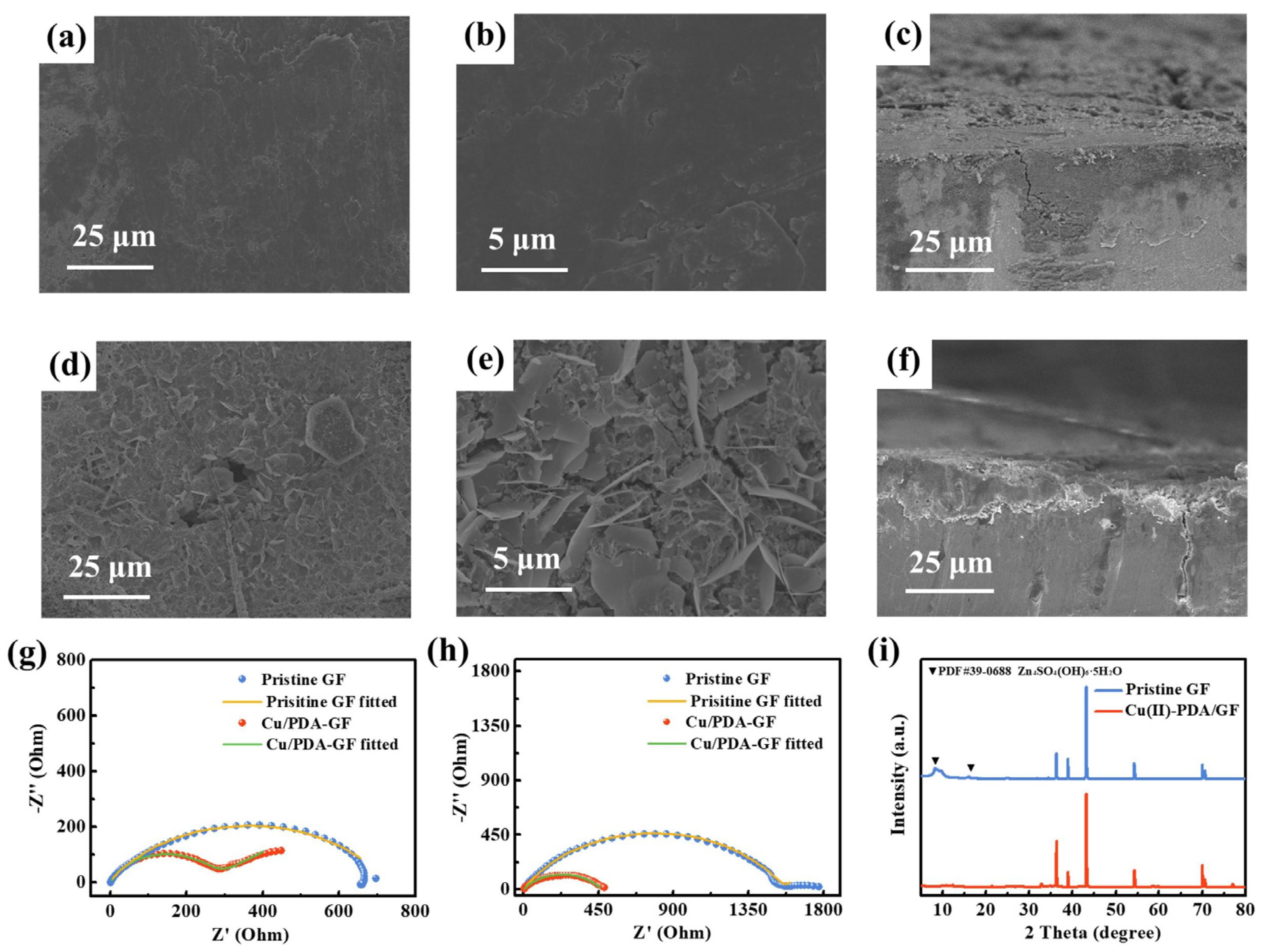
Figure 6.
Effect of Cu(II)-PDA/GF separator on the electrochemical performance of Zn//V2O5 full cells: (a) CV curves of the cell using Cu(II)-PDA/GF separator measured at the scan rate of 0.05 mV s−1; (b) rate performance of the cells using different separators at the current densities from 0.2 to 2 A g−1; (c) charge/discharge curves of the full cell using Cu(II)-PDA/GF separator; (d) cycle life and coulombic efficiency of the full cells using different separators at the current density of 2 A g−1.

Disclaimer/Publisher’s Note: The statements, opinions and data contained in all publications are solely those of the individual author(s) and contributor(s) and not of MDPI and/or the editor(s). MDPI and/or the editor(s) disclaim responsibility for any injury to people or property resulting from any ideas, methods, instructions or products referred to in the content. |
© 2023 by the authors. Licensee MDPI, Basel, Switzerland. This article is an open access article distributed under the terms and conditions of the Creative Commons Attribution (CC BY) license (https://creativecommons.org/licenses/by/4.0/).
Share and Cite
MDPI and ACS Style
Ma, F.; Xie, K.; Wu, S.; Zhang, C.; Liao, X.; Wang, Q. Cu(II)/Polydopamine-Modified Glass Fiber Separators for High-Performance Zinc-Ion Batteries. Batteries 2023, 9, 387. https://doi.org/10.3390/batteries9070387
AMA Style
Ma F, Xie K, Wu S, Zhang C, Liao X, Wang Q. Cu(II)/Polydopamine-Modified Glass Fiber Separators for High-Performance Zinc-Ion Batteries. Batteries. 2023; 9(7):387. https://doi.org/10.3390/batteries9070387
Chicago/Turabian StyleMa, Fengcan, Kaixuan Xie, Siheng Wu, Chi Zhang, Xiaodie Liao, and Qinghong Wang. 2023. "Cu(II)/Polydopamine-Modified Glass Fiber Separators for High-Performance Zinc-Ion Batteries" Batteries 9, no. 7: 387. https://doi.org/10.3390/batteries9070387
Note that from the first issue of 2016, this journal uses article numbers instead of page numbers. See further details here.