Article

High Flashpoint and Eco-Friendly Electrolyte Solvent for Lithium-Ion Batteries

1
Electrical Energy Storage Systems, Institute for Photovoltaics, University of Stuttgart, Pfaffenwaldring 47, 70569 Stuttgart, Germany
2
Karlsruhe Institute of Technology (KIT), Institute for Applied Materials-Applied Materials Physics (IAM-AWP), Hermann-von-Helmholtz-Platz 1, 76344 Eggenstein-Leopoldshafen, Germany
*
Author to whom correspondence should be addressed.
These authors contributed equally to this work.
Batteries 2023, 9(7), 348; https://doi.org/10.3390/batteries9070348
Submission received: 25 October 2022 / Revised: 22 June 2023 / Accepted: 26 June 2023 / Published: 28 June 2023

Abstract

:
Since Sony launched the commercial lithium-ion cell in 1991, the composition of the liquid electrolytes has changed only slightly. The electrolyte consists of highly flammable solvents and thus poses a safety risk. Solid-state ion conductors, classified as non-combustible and safe, are being researched worldwide. However, they still have a long way to go before being available for commercial cells. As an alternative, this study presents glyceryl tributyrate (GTB) as a flame retardant and eco-friendly solvent for liquid electrolytes for lithium-ion cells. The remarkably high flashpoint ( T FP = 174 ° C) and the boiling point ( T BP = 287 ° C) of GTB are approximately 150 K higher than that of conventional linear carbonate components, such as ethyl methyl carbonate (EMC) or diethyl carbonate (DEC). The melting point ( T MP = 75 ° C) is more than 100 K lower than that of ethylene carbonate (EC). A life cycle test of graphite/NCM with 1 M LiTFSI dissolved in GTB:EC (85:15 wt) achieved a Coulombic efficiency of above 99.6% and the remaining capacity resulted in 97% after 50 cycles ( C / 4 ) of testing. The flashpoint of the created electrolyte is T FP = 172 ° C and, therefore, more than 130 K higher than that of state-of-the-art liquid electrolytes. Furthermore, no thermal runaway was observed during thermal abuse tests. Compared to the reference electrolyte LP40, the conductivity of the GTB-based is reduced, but the electrochemical stability is highly improved. GTB-based electrolytes are considered an interesting alternative for improving the thermal stability and safety of lithium-ion cells, especially in low power-density applications.

1. Introduction

The market for portable devices containing lithium-ion batteries is growing steadily. However, there is still a great need for research and development in the field of lithium-ion batteries to improve performance and safety. Thermal safety is essential in the development of lithium-ion batteries. In the worst case, a cell malfunction can lead to a thermal runaway. Improving the thermal safety of lithium-ion batteries can be achieved in several ways. One option is to develop enhanced temperature determination, which records the core temperature of each cell to detect a thermal runaway at an early stage [1,2,3,4]. Other options include phase change materials for passive cooling of the cells [5] or making the cell’s chemistry safer [6,7]. In this study, we address the advancement of cell chemistry. The electrolyte is considered a critical component concerning thermal safety. Since Sony’s realization of the lithium-ion cell in 1991, the electrolyte composition in most commercial cells has changed only slightly. It still consists mainly of carbonate-based solvents [8,9,10]. Furthermore, it consists of lithium-conducting salts and various additives [11,12]. The usage of conventional solvents for electrolytes with low boiling points and flashpoints ( T FP ) such as ethyl methyl carbonate (EMC, T FP 22 ° C [13]), dimethyl carbonate (DMC, T FP < 20 ° C [14]), or diethyl carbonate (DEC, T FP 25 ° C [15]) pose an increased risk of inflammation of lithium-ion cells [16,17,18]. Due to the low boiling point, which produces high-pressure gradients at moderate temperatures (<100 ° C), there is a risk of cell explosion at high temperatures. In addition, the chemical products of the burned fluorine-containing electrolytes pose a particular health risk because they are highly toxic [19,20,21,22].
There are several approaches to improving thermal safety, but they usually come with other disadvantages. Many studies are devoted to the research of solid electrolytes. However, these bring significant challenges. For some solid electrolytes, conductivity is up to several orders of magnitude lower than for liquid electrolytes [23,24]. Even if new materials have grain conductivities in the range of their liquid counterparts, they still face interfacial challenges between the various components. In contrast to liquid electrolytes, it is difficult to cover the electrode particles with solid particles without gaps completely. Therefore, further improving existing liquid electrolyte systems is of great interest.
Swiderska et al. present an overview of 33 solvents and electrolytes used in lithium-ion cells. They focus on possible correlations between flashpoint (FP), self-extinguishing time, flame propagation time (FPT), flame propagation velocity (FPV), and differential scanning calorimetry. A correlation could be found only between FP vs. FPT and FP vs. FPV. Therefore, increasing the flashpoint is an opportunity to improve thermal safety [25]. Using ionic liquids can increase the flashpoint of liquid electrolytes, but these ionic liquids come at a high cost [26,27,28,29]. Flame retardant additives such as organic phosphates [30] or phosphonates [31] increase thermal safety but reduce cell performance. [32].
In this study, we focus on the investigation of co-solvents with higher flashpoints. Investigations on co-solvents were done before by several groups. Isken et al. showed that co-solvents could increase the flashpoint significantly from T FP , EC : DEC 36 ° C of the EC:DEC (3:7 wt) mixture to T FP , EC : ADN 149 ° C of the EC:ADN (1:1 wt) mixture. They showed that electrolytes with higher flashpoints could be formulated by substituting volatile carbonates. However, co-solvents are often accompanied by other disadvantages. The melting point (MP) of ADN T MP , ADN 2 ° C is too high for low-temperature applications. There are other solvents with lower working temperature applicability ( T < 0 ° C), such as sulfones [33,34]. Unfortunately, most of these solvents are ecologically harmful. Further co-solvents such as tributyl acetylcitrate (TBAC, T FP 217 ° C [35]) are not harmful to the environment, and the MP is T MP , TBAC 80 ° C [36]. However, the conductivity of TBAC-based electrolytes is worse than that of conventional solvents and requires DEC to build a functional cell.
This study presents glyceryl tributyrate as an environmentally friendly high flashpoint electrolyte solvent for lithium-ion cells. Glyceryl tributyrate (GTB) shows similar properties to TBAC. It is environmentally friendly, and the melting point is T MP , ADN 75 ° C. The flashpoint of GTB is T FP 174 ° C, and the boiling point is T BP 287 ° C [37]. In addition, GTB is non-toxic and is known as a nutritional supplement in animal husbandry [38]. Furthermore, the usage of DEC is not required. In combination with conventional solvents such as EC, it is possible to improve the flashpoint of the electrolyte and, thus, the safety of lithium-ion cells.

2. Materials and Methods

2.1. Materials

Glyceryl tributyrate (GTB, purity > 99%, Sigma Aldrich, Darmstadt, Germany), was dried over a molecular sieve (mesh size ≈ 0.3 nm) in a glovebox exposed to an argon atmosphere overnight (moisture content of less than 0.5 ppm). The chemical structure of GTB is shown in Figure 1 [37]. Ethylene carbonate (EC, purity 99%), ethyl methyl carbonate (EMC, purity > 99.9%) both from Sigma Aldrich, Germany, diethyl carbonate (DEC, purity > 99.9%, Carl Roth, Karlsruhe, Germany), dimethyl carbonate (DMC), fluoroethylene carbonate (FEC) both from BASF, Ludwigshafen, Germany, and lithium-bis(trifluoromethanesulfonyl)imide (LiTFSI, purity > 99%, from IOLITEC GmbH, Heilbronn, Germany) were opened in the glovebox and were used as received. Graphite electrodes (3 mAh/cm 2 , provided by Varta AG, Ellwangen, Germany), and lithium nickel manganese cobalt oxide electrodes (NCM 622, 1.3 mAh/cm 2 , provided by Münster Electrochemical Energy Technology, Münster, Germany) were punched into 18 mm coins and dried in a vacuum oven (B-585 from Buechi Labortechnik AG, Flawil, Switzerland, p < 50 mbar, T = 120 ° C). The separator Freudenberg 2190 (from Freudenberg, Weinheim, Germany) (thickness = 200 μ m) was punched into coins, 21 mm in diameter and dried in a vacuum oven ( p < 50 mbar, T = 120 ° C). For reference measurements, the electrolyte Selectilyte LP40 (composition 1 M LiPF 6 in EC:DEC 1:1 from BASF, Ludwigshafen, Germany) was used.

2.2. Electrolyte Preparation

The electrolytes were prepared in an argon-filled glovebox (H 2 and O 2 content lower than 0.5 ppm). GTB was combined with EC at a ratio of 85% GTB to 15% EC (in wt) and LiTFSI with a salt concentration of 1 M. The mixture was also combined with FEC, EMC, DMC, and DEC for further investigations.

2.3. Cell Preparation

For characterization, the cells were built as coin cells in PAT-Cell or ECC-Ref cells from EL Cell Germany (Hamburg, Germany). For cycle life and C-rate tests, the cells were constructed with NCM as the working electrode and graphite as the counter electrode. The polypropylene separator (Freudenberg FS2190) was wetted on both sides with a total of V = 120 μ L of the selected electrolyte before inserting the electrodes.

2.4. Flashpoint Measurement

The FP measurements of the new electrolyte mixtures were carried out with the flashpoint tester NPV Tech (from NORMALAB, Valliquerville, France) according to the norm ISO 3679: Determination of flash point Rapid equilibrium closed cup method. First, the container of the test fixture was partially filled with the liquid electrolyte and sealed. The container was then heated step by step until enough flammable gases were produced to be ignited by a glowing wire, and the ignition spread over the entire surface of the test specimen. This method was used to determine the temperature range of the flashpoint. For accurate determination, the electrolyte was filled into the test container and was heated to a temperature slightly lower than the previously determined flashpoint. Once the temperature stabilized, the measurement was conducted using the glowing wire. If the electrolyte did not ignite, the apparatus was cooled down, a fresh electrolyte was filled into the container, and the temperature was set to 0.5 K above the previous test temperature. This procedure was repeated until ignition occurred.

2.5. Conductivity Measurements

The conductivity of the electrolyte was determined using the sealed glass conductivity cell Platinized HTCC Conductivity Cell (from BioLogic, Knoxville, TN, USA) with platinized electrodes and the LCR meter IM3533-01 from Hioki, Japan. The frequency was f = 1 kHz. For temperature stabilization, the glass conductivity cell was immersed in the Proline RP 845 C cryostat from Lauda, Germany.

2.6. Cell Tests

Life cycle tests were evaluated by cyclic testing with constant charge and discharge current using the CTS battery tester (from BaSyTec, Asselfingen, Germany). To stabilize the ambient temperature, all cell tests were performed in an IPP 100 thermal chamber from Memmert, Germany, at a constant temperature of T = 25 ± 0.1 ° C. First, three formation cycles were performed at I = C /10 in a potential range from U = 2.5 V to U = 4.2 V, then five formation cycles were performed at I = C /6 followed by full constant current cycles at I charge = C /6 and I discharge = C /4.

2.7. Cyclic Voltammetry Measurements (CV)

Two electrode cells with inert stainless steel as working, counter, and reference electrodes were used for cyclic voltammetry measurements. Cyclic voltammetry measurements were performed using a Reference 3000 AE from Gamry, Warminster, PA, USA. Electrochemical stability was measured by linear sweep voltammetry. The sampling rate was set to 0.5 mV/s, and the potential limits were set from 4.3 V to 4.3 V against stainless steel. In addition, cyclic voltammetry measurements were performed on graphite as a working electrode and lithium as counter and reference electrode with a sampling rate of 20 μ V/s in a potential range of 0.6 V to 0.01 V.

2.8. Electrochemical Impedance Spectroscopy (EIS)

EIS measurements were performed for graphite/NCM cells. Excitation was applied galvanostatically with C/50 in a frequency range between f = 10 kHz and f = 10 mHz at S O C = 50 % with a Reference 3000 AE from Gamry, Warminster, PA, USA in an IPP 100 thermal chamber from Memmert, Germany at T = 25 ± 0.1 ° C. The diameter of the semicircle was used to define the charge transfer resistance Rct.

2.9. Thermal Abuse Test

The heat-wait-seek (HWS) test was utilized for conducting thermal abuse experiments, according to the procedure described in [39]. The ES ARC from Thermal Hazard Technology (Bletchley, UK) was used for this purpose. This device is sensitive enough to accurately measure the thermal behavior of coin cells with a capacity in the 5 mAh range [40,41]. In addition, in order to increase the amount of active material and electrolytes, four coin cells were stacked for the tests. This cell stack has a capacity of around 12 mAh. This test involved a sequence of heating, waiting, and seeking intervals. The initial heating phase commenced by directly raising the temperature from the laboratory level to T = 35 ° C. The waiting phase allowed for thermal equilibrium to be achieved after each heating step of 5 K. During the seeking phase, the temperatures of two thermocouples were compared, one placed near the heater and the other near the sample. If a difference in temperature between these thermocouples was observed, the heating rate was determined. If the rate exceeded the predefined threshold of 0.02 ° C/min, self-heating was detected, and the system switched to a (quasi-)adiabatic mode known as the exotherm mode. In this mode, heat transfer to the chamber was prevented, enabling the exothermal reaction of the cell. Consequently, the cell’s temperature continued to rise until either thermal runaway occurred or the chemicals for the exothermal reaction were depleted. Certain events, such as venting or endothermal reactions, could halt the self-heating of the cell, prompting another heating step until the cell became exothermal again or entered thermal runaway. A more comprehensive description of this experimental procedure can be found in [42]. To avoid damaging the calorimeter, the test was terminated at 300 ° C if thermal runaway had not been achieved prior to that point. It was assumed that if the cell had not entered runaway by this temperature, it was unlikely to do so thereafter. The waiting time between heating steps was 20 min. Because of the low capacity of the coin cells, four cells have been used for each test. The coin cells were taped together with the thermocouple of type E in the middle of the pack by heat-resistant tape from 3M Industrial Business (Neuss, Germany). The coin cells were placed in the middle of the calorimeter to provide a uniform heat transfer between the calorimeter and coin cells. The calibration of the ARC was performed according to the manufacturer’s recommendation using coin cell dummies with a similar heat capacity and the same experimental setup. The calibration was followed by a so-called drift check to ensure successful calibration.

3. Results

Glyceryl tributyrate is presented as an environmentally friendly electrolyte solvent for lithium-ion cells. Table 1 shows the melting, flash, and boiling point of GTB, EC, EMC, and DEC. The boiling point, as well as the flashpoint T FP = 174 ° C of GTB, are nearly 150 K higher than that of EMC and DEC. The melting point is more than 100 K lower than that of EC. In addition to the fact that GTB is environmentally friendly, the high flashpoint and the high boiling point are the main advantages of GTB as a solvent for lithium-ion batteries.
The main focus of this study lies in combining GTB with LiTFSI since other conducting salts are thermally less stable [44,45]. For completeness, further tests were also done with Lithium hexafluorophosphate (LiPF 6 ). However, it appeared that GTB is not chemically compatible with LiPF 6 as reactions of the solution were observed that resulted in color changes. Therefore, the combination with LiPF 6 will not be further discussed.

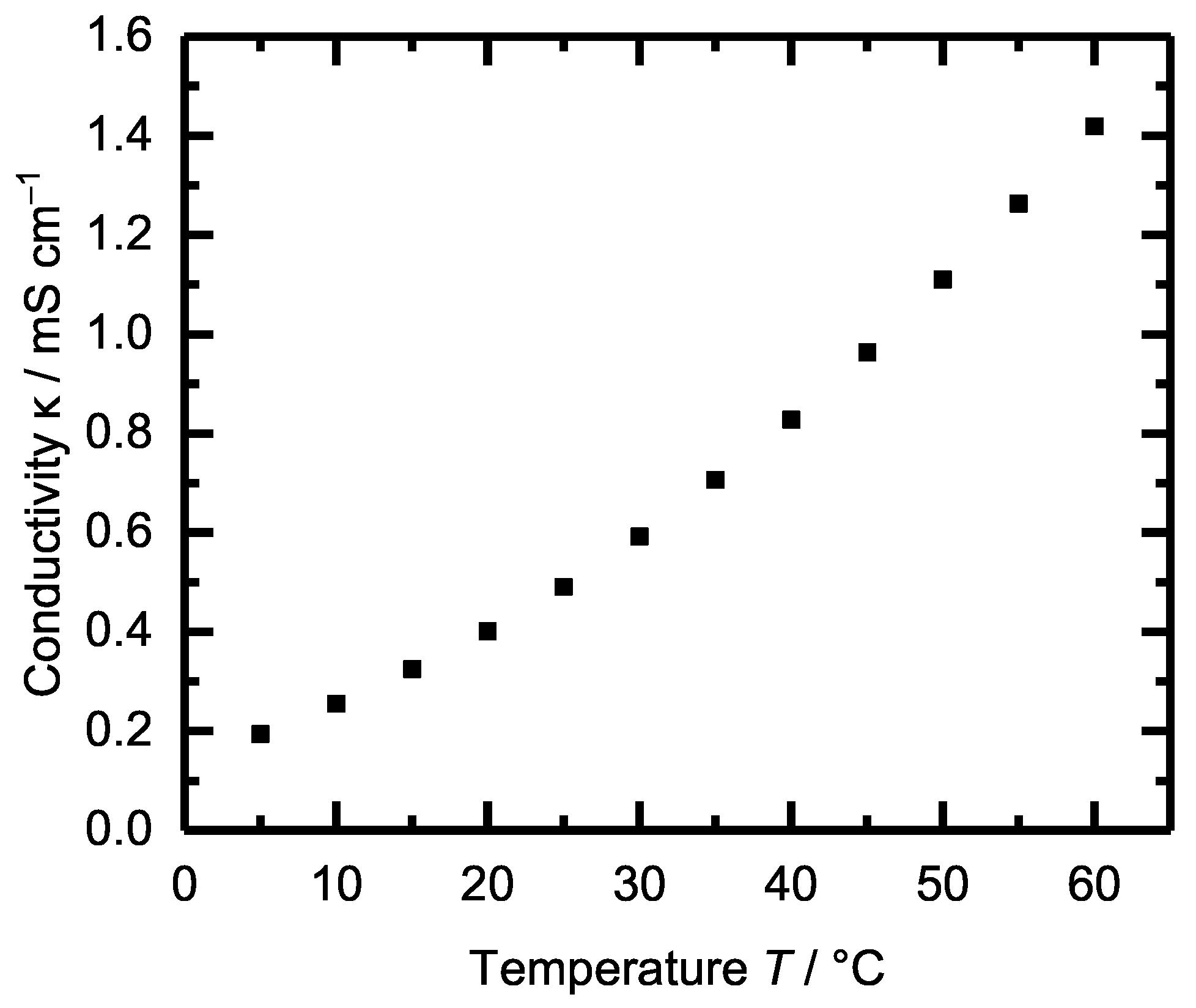
3.1. Flashpoint and Conductivity

The flashpoint of the electrolyte is of particular interest in this study. Conventional electrolytes like LP40 have a flashpoint of about T FP = 37 ° C [46]. Since lithium-ion cells easily reach temperatures above T > 50 ° C during operation, there is a high risk that inflammable gases escape in case the cell is mechanically damaged. The electrolyte measured in this study of 1 M LiTFSI dissolved in GTB:EC 85:15 wt. shows a flashpoint of T FP = 172 ± 1 ° C according to the norm ISO 3679. Compared to LP40, the flashpoint is increased by 135 K. By adding 20% diethyl carbonate or ethyl methyl carbonate to GTB-EC, the flashpoint is reduced to nearly T FP = 50 ± 1 ° C.
Figure 2 shows the conductivity of the new electrolyte (1 M LiTFSI in GTB:EC 85:15 wt.) at different temperatures between 5 ° C < T < 60 ° C. The conductivity of LP40 is about 8 mS/cm at 25 ° C and is about 16 times higher than that of the GTB-based electrolyte [47]. Therefore, electrolytes with GTB as solvents are considered for applications with low power density, such as smartphones and other portable devices.

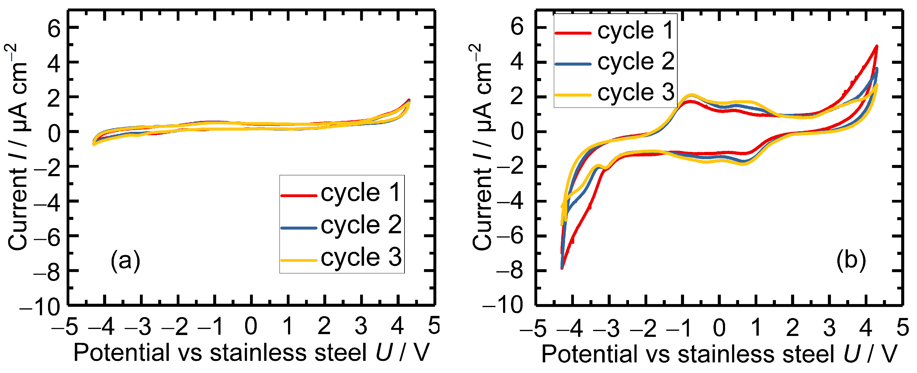
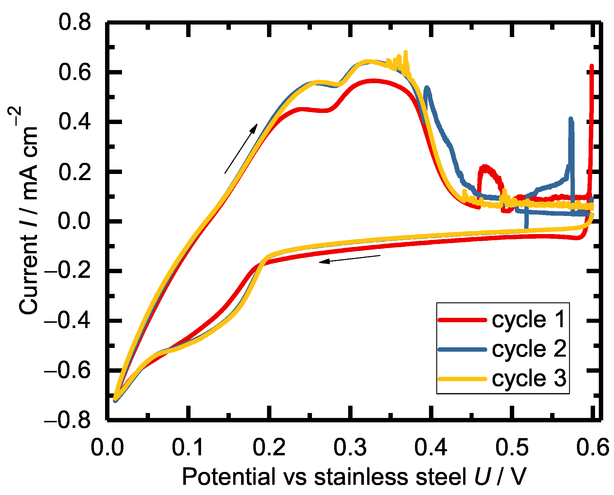
3.2. Cyclic Voltammetry

The electrochemical stability window of 1 M LiTFSI dissolved in GTB:EC 85:15 was determined with CV measurements between electrochemical inert stainless steel electrodes and is presented in Figure 3a. Therefore, the potential of a stainless steel working electrode connected to the electrolyte against stainless steel was scanned at 0.5 mVs 1 . As a reference, the stability window of LP40 was also measured and is shown in Figure 3b. The GTB-based electrolyte shows improved electrochemical stability compared to LP40 and seems stable over the total potential range. At 3.5 V vs. stainless steel, it rises but is still below 2 μ A/cm 2 . The GTB-based electrolyte (a) shows slight signs of oxidation and reduction at about U = 1.5 V and U = 2.5 V. However, the measured current remains less than I = 1 μ A at these points, and the peaks decrease with progressive cycling. Therefore, these peaks are assigned to side reactions triggered by impurities.

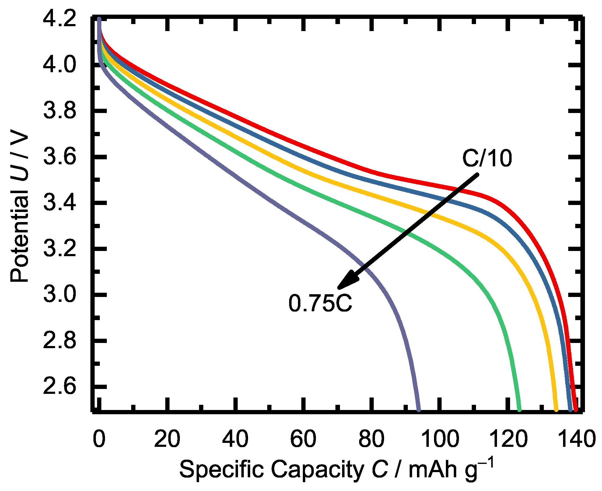
3.3. Life Cycle Test

The lithium salt concentration of 1 M LiTFSI seems to dissolve entirely in GTB. However, in a cell with NCM as the positive electrode and graphite as the negative electrode with LiTFSI in GTB, the Coulombic efficiency of the life cycle test was only about η coul = 10 % . By adding EC, the Coulombic efficiency increased above η coul 90 % . Different amounts of EC between 0% and 50% have been tested. The results are shown in Figure 4a). The best result was achieved with the mixture 1 M LiTFSI in GTB:EC (85:15 wt) with a Coulombic efficiency of η coul = 99.6 % .
Additives such as EMC and FEC were also investigated. GTB was combined with 15% EC and various amounts of FEC and EMC with 1 M LiTFSI. However, the addition of FEC decreased the Coulombic efficiency. The combination with EMC shows comparable results. The addition of EMC is not suitable for the objective of this study because the flashpoint of EMC is only T FP = 24 ° C. Therefore, it was not investigated further. The results are shown in Figure 4b). Here, the combination of 1 M LiTFSI in GTB with 15% EC (green) is used as reference.
Figure 4. Cycling performance of a graphite/NCM cell with (a): 1 M LiTFSI in GTB:EC (0% ≦ proportion of EC ≦ 50%), (b): 1 M LiTFSI in GTB:EC:(FEC or EMC) with a fixed amount of 15% EC. The solution of GTB:EC (85:15 wt) of Figure (a) is used as a reference. First, three formation cycles were performed at C-rate C / 10 followed by five cycles at C / 6 . After that, the cell was charged and discharged at C-rate I charge = C /6 and I discharge = C /4 at T = 25 ° C.
Batteries 09 00348 g004
Figure 5 shows the results of substituting GTB with DEC or DMC compared to the reference electrolyte (green line) with 1 M LiTFSI in GTB:EC (85:15 wt). All electrolytes contain 15% EC.
A higher capacity was taken by adding DMC at the beginning of the measurement. However, the cells show accelerated aging, which is why DMC is unsuitable for this electrolyte. The addition of DEC also significantly increases the removable capacity. DEC also shows higher aging than the reference consisting of GTB:EC (85:15 wt), but it is more stable than the DMC-based electrolyte. Like EMC, DEC has a very low flashpoint of T FP = 25 ° C. Since this work aims to increase the flashpoint, the addition of DEC is not targeted.
Figure 6 shows the cycling test results of a graphite/NCM cell. The left figure shows the electrolyte formulation with 1 M LiTFSI in GTB:EC (85:15 wt), and the right figure shows LP40 as a state-of-the-art reference. First, three cycles were performed at a C-rate of C / 10 , followed by five cycles at C / 6 for formation processes. After that, full cycles were done at a C-rate of I charge = C /6 and I discharge = C /4 for the GTB-based electrolyte and C / 2 for LP40 at T = 25 ° C.
For both electrolytes, the Coulombic efficiency achieved was η coul > 99.6 % . As mentioned earlier, the conductivity of the GTB-based electrolyte is an order of magnitude lower than that of LP40. Therefore, the applied C-rate is lower for the GTB-based electrolyte. The cycle performance of the two electrolytes is comparable. Further cycle life tests were performed with the GTB-based electrolyte at different temperatures. Figure 7 shows the reversible capacity C and Coulombic efficiency η coul at constant ambient temperatures of left: T amb = 10 ° C and right: T amb = 40 ° C. The measurements were performed as before with constant current charge/discharge. The C-rates were I charge = C /6 and I discharge = C /4.
The efficiency of both cells was over η coul > 99 %. At an ambient temperature of T amb = 10 ° C, it took approx. thirty-five cycles for the usable capacity to reach its maximum. This was approx. C = 120 mAh/g and thus corresponds to approx. 80% of the capacity available at T = 25 ° C. The lifetime test at T = 40 ° C is comparable to the results of the T = 25 ° C measurement from Figure 6, with the usable capacity C T = 40 ° C being about 10% higher than at C T = 25 ° C . This is due to the temperature-dependent conductivity. As shown in Figure 2, the conductivity η T = 40 ° C is almost doubled compared to η T = 25 ° C . As a result of the lower overvoltages, the voltage limits are reached later, and more charge can be converted. The charge-discharge profile of the second formation cycle of graphite/NCM cells with 1 M LiTFSI in GTB:EC (85:15 wt, blue) or LP40 (black) at T = 25 ° C at C-rate C / 10 are presented in Figure 8.
Figure 7. Cycling performance of graphite/NCM cells with 1 M LiTFSI in GTB:EC (85:15 wt) as electrolyte at left: T = 10 ° C and right: T = 40 ° C. The cells were cycled at C-rate I charge = C /6 and I discharge = C /4.
Batteries 09 00348 g007
As expected from the conductivity measurement, the cell with the GTB-based electrolyte shows a higher voltage offset than the LP40 electrolyte due to the lower conductivity of GTB. Due to the overvoltage, the end-of-charge voltage is reached earlier for the GTB cell than for the LP40 cell. Since no constant voltage charging was performed, the graphite is not completely lithiated, which is why the voltage drops significantly during the beginning of the discharge. Apart from the voltage offset, the curves are very similar. The different conductivities are also reflected in the EIS measurements. The EIS measurements for graphite/NCM cells with LP40 (blue) and the GTB-based electrolyte (red) are shown in the Nyquist plot in Figure 9.
The ohmic resistance R 0 of LP40 is R 0 = 2 m Ω cm 2 , while the R 0 of the GTB-based electrolyte is R 0 = 20 m Ω cm 2 , which is an order of magnitude higher. One of the reasons for this is the poorer conductivity of LiTFSI compared to LiPF6 [44,48]. The charge transfer resistance ( R c t ) of LP40 is roughly R c t = 1 m Ω cm 2 , the R c t of the GTB-based electrolyte is eight times higher with roughly R c t = 8 m Ω cm 2 . One reason could be poor negative electrode passivation and the corrosion of the aluminum current collector at the positive electrode by LiTFSI [49]. Figure 10 shows the cyclic voltammogram of a graphite/lithium cell with 1 M LiTFSI in GTB:EC (85:15 wt). The first three cycles in the range between 0.6 V and 0.01 V are reported. The first cycle shows a different behavior than the following cycles, which is assigned to the decomposition of EC, leading to the SEI formation on the graphite surface. The voltammogram of the second and third cycles shows that the Li-ion insertion process is highly reversible. Fluctuations in the voltage curve are visible during the deintercalation of the graphite electrode. These are attributed to the chemical instability of GTB against metallic lithium.
Figure 9. Nyquist plot of graphite/NCM cells with LP40 (blue) and 1 M LiTFSI in GTB:EC (85:15 wt, red) at T = 25 ° C.
Batteries 09 00348 g009
Figure 11 shows the discharge capacity and the potential profiles at different temperatures between T = 10   ° C and T = 70   ° C. At 10 ° C, the discharge capacity is reduced due to the reduced conductivity. The temperature range most suitable for this electrolyte is 30 ° C < T < 40 ° C. At temperatures between 50 ° C < T < 70 ° C, the capacity decreases slightly, but it is still above 95% of the total capacity.
Figure 12 shows the discharge capacity and the potential profiles at different C-rates. The applied currents were C/10, C/5, C/3, C/2 and 0.75C. At a current rate of 0.75C, the usable capacity dropped to 65% of the initial capacity.

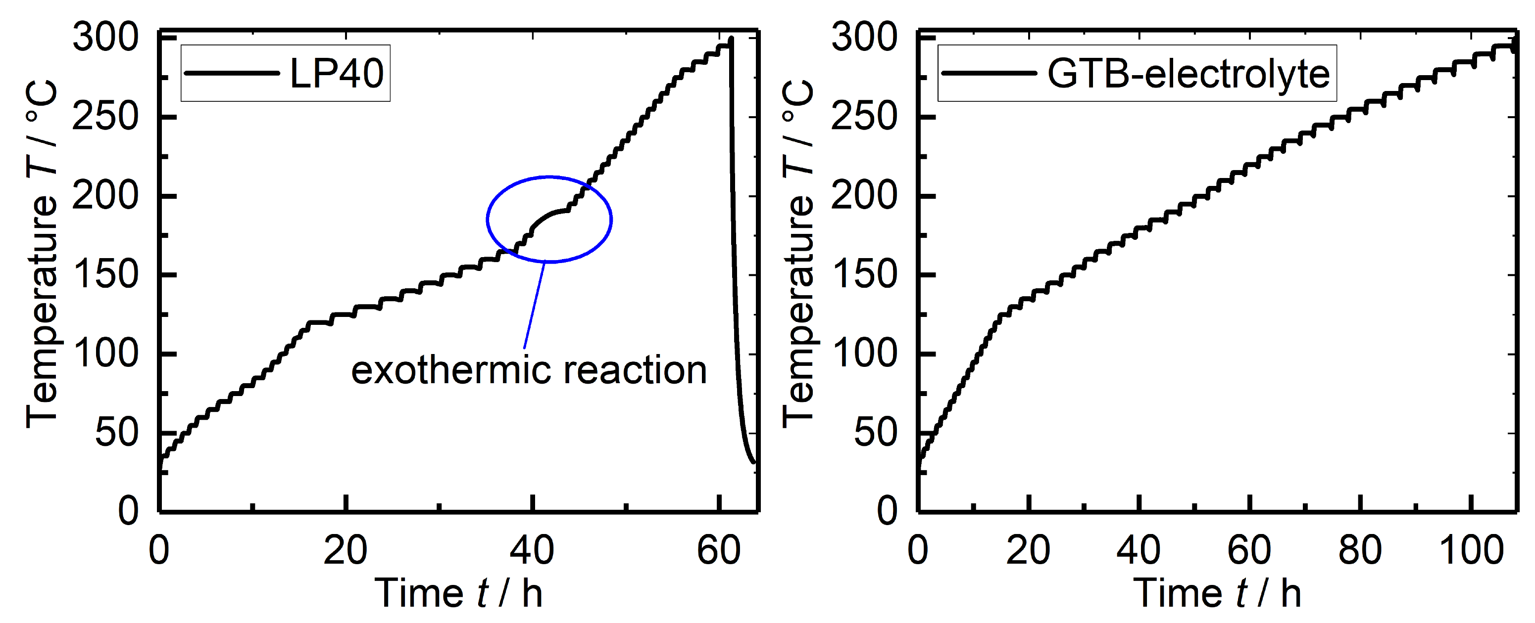
3.4. Thermal Abuse Test

To analyze the thermal safety of the new electrolyte, thermal abuse measurements were performed using the heat-wait-seek test in an accelerating rate calorimeter. For this purpose, graphite/NCM coin cells of the CR2016 format with LP40 or the GTB-based electrolyte (1 M LiTFSI in GTB:EC 85:15) were produced and investigated. The SoC of all cells was at 100%. The cells were heated in Δ T = 5 ° C steps and observed during a 20 min waiting period to see if exothermic reactions occurred. The results are presented in Figure 13. The figure on the left shows the results of the LP40 electrolyte. At approx. T = 170 ° C, a clear temperature increase can be seen. This temperature increase indicates exothermic reactions in the cells, which possibly leads to thermal runaway for cells with higher capacity.
The graph to the right of Figure 13 shows the results for the GTB-based electrolyte. Exothermic reactions or a thermal runaway is not discernible. It is likely that reactions and exothermic processes occur within the cells during heating up to T = 300 ° C, but the thermal energy released is too low to trigger the exothermal mode of the ARC or even a thermal runaway.

4. Discussion

The solution mixture of 1 M LiTFSI in GTB:EC 85:15 wt was developed as a suitable electrolyte composition for lithium-ion cells. The addition of other solvents (DEC, DMC, EMC, and FEC) can lead to an improvement in conductivity, but this is accompanied by a reduction in flashpoints. The combination of FEC and DMC also reduces the cyclic stability. The conducting salt LiPF 6 appears to be chemically incompatible with GTB. However, the conductive salt LiTFSI is preferred anyway since it decomposes at temperatures above T 300 ° C [45]. The solvent GTB is not harmful to the environment and is flame retardant; its flashpoint is at T 174 ° C. The flashpoint of the GTB:EC electrolyte was measured to T 172 ° C, which is significantly higher than that of LP40 ( T 37 ° C). Cycle life measurements of an NCM/graphite cell at a current of I charge = C /6 and I discharge = C /4 give a Coulombic efficiency of 99.6%.
At ambient temperature, the conductivity of GTB is by one order of magnitude lower than that of LP40 but by nearly two orders of magnitudes higher than the conductivity of some solid-state electrolytes. Unlike solid electrolytes such as polyethylene oxide, GTB-based systems do not have to be heated to T = 60 ° C but can also be operated at low temperatures. Compared to conventional liquid electrolytes, the GTB-based electrolyte is more suitable for applications where the power density is less than C/4. In low-power applications, GTB shows some advantages. Based on the cyclic voltammetry measurement, the electrochemical stability of the GTB-based electrolyte seems to be improved compared to LP40. The thermal abuse tests clearly show an improvement in the thermal safety of the new electrolyte compared to the standard LP40 electrolyte, as no exothermic reactions or thermal runaway was observed in cells with an SoC of 100%. Even at temperatures up to T = 300 ° C, no intense exothermic heat release, which might lead to thermal runaway, was observed. Since the electrolyte exhibits stable behavior at ambient temperatures of 30 ° C to 40 ° C degrees, its conductivity increases with rising temperature, and its exceptionally high flashpoint makes it difficult to ignite, it is particularly suitable for high-temperature applications.

5. Conclusions

In this study, we investigated Glyceryl tributyrate as a novel electrolyte solvent for lithium-ion cells. The main advantages of GTB are that it is not harmful to the environment and its flashpoint of T FP = 174 ° C, as well as the boiling point of T BP = 287 ° C are approx. 150 K higher than that of EMC and DEC. The melting point of GTB ( T MP = 75 ° C) is more than 100 K lower than that of EC and, therefore, also suitable for applications at low temperatures. Based on the cyclic voltammetry measurement, the studied electrolyte of 1 M LiTFSI in GTB:EC (85:15 wt.) shows improved electrochemical stability compared to the reference electrolyte LP40. The flashpoint of this mixture was measured to T FP = 172 ° C. No exothermic heat release or thermal runaway were observed during thermal abuse tests. In graphite/NCM cells, the Coulombic efficiency is above η coul = 99.6 % . Thus GTB combined with EC and LiTFSI represents a great step forward in terms of the thermal safety of lithium-ion cells, especially in the field of high-temperature applications.

Author Contributions

Conceptualization, M.S. and K.P.B.; methodology, M.S., L.K., C.Z. and K.P.B.; investigation, M.S., L.K., J.P.-B., P.F. and J.H.; writing—original draft preparation, M.S. and L.K.; writing—review and editing, J.H., J.P.-B., P.F., C.Z. and K.P.B.; visualization, M.S. and L.K.; supervision, K.P.B.; project administration, M.S.; funding acquisition, K.P.B. All authors have read and agreed to the published version of the manuscript.

Funding

This research was funded by the Bundesministerium fuer Bildung und Forschung within the BCT—Battery Cell Technology project (03XP0109H). This research was partly funded by the Helmholtz Association, in the programme Materials and Technologies for the Energy Transition (MTET), and we want to express our gratitude for the funding. This work also contributes to the research performed at CELEST (Center of Electrochemical Energy Storage Ulm-Karlsruhe).

Institutional Review Board Statement

Not applicable.

Informed Consent Statement

Not applicable.

Data Availability Statement

Not applicable.

Acknowledgments

The authors thank Münster Electrochemical Energy Technology for providing the NCM622 electrode material and Varta AG for providing the graphite electrode material. Thanks also go to Jonas Landsgesell for his helpful ideas.

Conflicts of Interest

The authors declare no conflict of interest. The funders had no role in the design of the study; in the collection, analyses, or interpretation of data; in the writing of the manuscript, or in the decision to publish the results.

References

  1. Raijmakers, L.; Danilov, D.; Eichel, R.A.; Notten, P. A review on various temperature-indication methods for Li-ion batteries. Appl. Energy 2019, 240, 918–945. [Google Scholar] [CrossRef]
  2. Surya, S.; Marcis, V.; Williamson, S. Core temperature estimation for a lithium ion 18,650 cell. Energies 2020, 14, 87. [Google Scholar] [CrossRef]
  3. Wang, L.; Lu, D.; Song, M.; Zhao, X.; Li, G. Instantaneous estimation of internal temperature in lithium-ion battery by impedance measurement. Int. J. Energy Res. 2020, 44, 3082–3097. [Google Scholar] [CrossRef]
  4. Ströbel, M.; Pross-Brakhage, J.; Kopp, M.; Birke, K.P. Impedance based temperature estimation of lithium ion cells using artificial neural networks. Batteries 2021, 7, 85. [Google Scholar] [CrossRef]
  5. Jiang, K.; Liao, G.; Jiaqiang, E.; Zhang, F.; Chen, J.; Leng, E. Thermal management technology of power lithium-ion batteries based on the phase transition of materials: A review. J. Energy Storage 2020, 32, 101816. [Google Scholar] [CrossRef]
  6. Deng, K.; Zeng, Q.; Wang, D.; Liu, Z.; Wang, G.; Qiu, Z.; Zhang, Y.; Xiao, M.; Meng, Y. Nonflammable organic electrolytes for high-safety lithium-ion batteries. Energy Storage Mater. 2020, 32, 425–447. [Google Scholar] [CrossRef]
  7. Wang, Q.; Jiang, L.; Yu, Y.; Sun, J. Progress of enhancing the safety of lithium ion battery from the electrolyte aspect. Nano Energy 2019, 55, 93–114. [Google Scholar] [CrossRef]
  8. Yoshino, A.; Sanechika, K.; Nakajima, T. Secondary Battery. Patent US4668595A, 26 May 1987. [Google Scholar]
  9. Yoshino, A. The birth of the lithium-ion battery. Angew. Chem. Int. Ed. 2012, 51, 5798–5800. [Google Scholar] [CrossRef]
  10. Nishi, Y. The dawn of lithium-ion batteries. Electrochem. Soc. Interface 2016, 25, 71. [Google Scholar] [CrossRef]
  11. Xu, K. Nonaqueous liquid electrolytes for lithium-based rechargeable batteries. Chem. Rev. 2004, 104, 4303–4418. [Google Scholar] [CrossRef] [PubMed]
  12. Xu, K. Electrolytes and interphases in Li-ion batteries and beyond. Chem. Rev. 2014, 114, 11503–11618. [Google Scholar] [CrossRef]
  13. MERCK KGaA. Ethyl Methyl Carbonate, CAS Number 623-53-0; Merck KGaA: Darmstadt, Germany, 2022. [Google Scholar]
  14. MERCK KGaA. Dimethyl Carbonate, CAS Number 616-38-6; Merck KGaA: Darmstadt, Germany, 2022. [Google Scholar]
  15. MERCK KGaA. Diethyl Carbonate, CAS Number 105-58-8; Merck KGaA: Darmstadt, Germany, 2022. [Google Scholar]
  16. Hofmann, A.; Hanemann, T. Novel electrolyte mixtures based on dimethyl sulfone, ethylene carbonate and LiPF6 for lithium-ion batteries. J. Power Sources 2015, 298, 322–330. [Google Scholar] [CrossRef]
  17. Hess, S.; Wohlfahrt-Mehrens, M.; Wachtler, M. Flammability of Li-ion battery electrolytes: Flash point and self-extinguishing time measurements. J. Electrochem. Soc. 2015, 162, A3084. [Google Scholar] [CrossRef]
  18. Lisbona, D.; Snee, T. A review of hazards associated with primary lithium and lithium-ion batteries. Process. Saf. Environ. Prot. 2011, 89, 434–442. [Google Scholar] [CrossRef]
  19. Lei, B.; Zhao, W.; Ziebert, C.; Uhlmann, N.; Rohde, M.; Seifert, H.J. Experimental analysis of thermal runaway in 18650 cylindrical Li-ion cells using an accelerating rate calorimeter. Batteries 2017, 3, 14. [Google Scholar] [CrossRef] [Green Version]
  20. Hammami, A.; Raymond, N.; Armand, M. Runaway risk of forming toxic compounds. Nature 2003, 424, 635–636. [Google Scholar] [CrossRef]
  21. Larsson, F. Assessment of Safety Characteristics for Li-Ion Battery Cells by Abuse Testing; Department of Applied Physics, Chalmers University of Technology: Gothenborg, Sweden, 2014; p. 94. [Google Scholar]
  22. Larsson, F.; Andersson, P.; Blomqvist, P.; Lorén, A.; Mellander, B.E. Characteristics of lithium-ion batteries during fire tests. J. Power Sources 2014, 271, 414–420. [Google Scholar] [CrossRef]
  23. Raju, M.M.; Altayran, F.; Johnson, M.; Wang, D.; Zhang, Q. Crystal structure and preparation of Li7La3Zr2O12 (LLZO) solid-state electrolyte and doping impacts on the conductivity: An overview. Electrochem 2021, 2, 390–414. [Google Scholar] [CrossRef]
  24. Vinnichenko, M.; Waetzig, K.; Aurich, A.; Baumgaertner, C.; Herrmann, M.; Ho, C.W.; Kusnezoff, M.; Lee, C.W. Li-Ion Conductive Li1.3Al0.3Ti1.7(PO4)3 (LATP) Solid Electrolyte Prepared by Cold Sintering Process with Various Sintering Additives. Nanomaterials 2022, 12, 3178. [Google Scholar] [CrossRef] [PubMed]
  25. Swiderska-Mocek, A.; Jakobczyk, P.; Rudnicka, E.; Lewandowski, A. Flammability parameters of lithium-ion battery electrolytes. J. Mol. Liq. 2020, 318, 113986. [Google Scholar] [CrossRef]
  26. Kim, G.; Jeong, S.; Joost, M.; Rocca, E.; Winter, M.; Passerini, S.; Balducci, A. Use of natural binders and ionic liquid electrolytes for greener and safer lithium-ion batteries. J. Power Sources 2011, 196, 2187–2194. [Google Scholar] [CrossRef]
  27. Lux, S.F.; Schmuck, M.; Jeong, S.; Passerini, S.; Winter, M.; Balducci, A. Li-ion anodes in air-stable and hydrophobic ionic liquid-based electrolyte for safer and greener batteries. Int. J. Energy Res. 2010, 34, 97–106. [Google Scholar] [CrossRef]
  28. Tsurumaki, A.; Agostini, M.; Poiana, R.; Lombardo, L.; Lufrano, E.; Simari, C.; Matic, A.; Nicotera, I.; Panero, S.; Navarra, M.A. Enhanced safety and galvanostatic performance of high voltage lithium batteries by using ionic liquids. Electrochim. Acta 2019, 316, 1–7. [Google Scholar] [CrossRef]
  29. Navarra, M.A. Ionic liquids as safe electrolyte components for Li-metal and Li-ion batteries. MRS Bull. 2013, 38, 548. [Google Scholar] [CrossRef]
  30. Xu, K.; Ding, M.S.; Zhang, S.; Allen, J.L.; Jow, T.R. Evaluation of fluorinated alkyl phosphates as flame retardants in electrolytes for Li-ion batteries: I. Physical and electrochemical properties. J. Electrochem. Soc. 2003, 150, A161. [Google Scholar] [CrossRef]
  31. Dalavi, S.; Xu, M.; Ravdel, B.; Zhou, L.; Lucht, B.L. Nonflammable electrolytes for lithium-ion batteries containing dimethyl methylphosphonate. J. Electrochem. Soc. 2010, 157, A1113. [Google Scholar] [CrossRef]
  32. Kalhoff, J.; Eshetu, G.G.; Bresser, D.; Passerini, S. Safer electrolytes for lithium-ion batteries: State of the art and perspectives. ChemSusChem 2015, 8, 2154–2175. [Google Scholar] [CrossRef]
  33. Sun, X.G.; Angell, C.A. New sulfone electrolytes for rechargeable lithium batteries: Part I. Oligoether-containing sulfones. Electrochem. Commun. 2005, 7, 261–266. [Google Scholar] [CrossRef]
  34. Xu, K.; Angell, C.A. Sulfone-based electrolytes for lithium-ion batteries. J. Electrochem. Soc. 2002, 149, A920. [Google Scholar] [CrossRef]
  35. MERCK KGaA. Tributyl Acetylcitrat, CAS Number 77-90-7; Merck KGaA: Darmstadt, Germany, 2022. [Google Scholar]
  36. Ströbel, M.; Kiefer, L.; Birke, K.P. Investigation of a novel ecofriendly electrolyte-solvent for lithium-ion batteries with increased thermal stability. Batteries 2021, 7, 72. [Google Scholar] [CrossRef]
  37. MERCK KGaA. Glyceryl Tributyrate, CAS Number 60-01-5; Merck KGaA: Darmstadt, Germany, 2022. [Google Scholar]
  38. Masmeijer, C.; Rogge, T.; van Leenen, K.; De Cremer, L.; Deprez, P.; Cox, E.; Devriendt, B.; Pardon, B. Effects of glycerol-esters of saturated short-and medium chain fatty acids on immune, health and growth variables in veal calves. Prev. Vet. Med. 2020, 178, 104983. [Google Scholar] [CrossRef]
  39. Ohneseit, S.; Finster, P.; Floras, C.; Lubenau, N.; Uhlmann, N.; Seifert, H.J.; Ziebert, C. Thermal and Mechanical Safety Assessment of Type 21700 Lithium-Ion Batteries with NMC, NCA and LFP Cathodes–Investigation of Cell Abuse by Means of Accelerating Rate Calorimetry (ARC). Batteries 2023, 9, 237. [Google Scholar] [CrossRef]
  40. Hofmann, A.; Migeot, M.; Thißen, E.; Schulz, M.; Heinzmann, R.; Indris, S.; Bergfeldt, T.; Lei, B.; Ziebert, C.; Hanemann, T. Electrolyte Mixtures Based on Ethylene Carbonate and Dimethyl Sulfone for Li-Ion Batteries with Improved Safety Characteristics. ChemSusChem 2015, 8, 1892–1900. [Google Scholar] [CrossRef] [PubMed]
  41. Mohsin, I.U.; Ziebert, C.; Rohde, M.; Seifert, H.J. Comprehensive Electrochemical, Calorimetric Heat Generation and Safety Analysis of Na0.53MnO2 Cathode Material in Coin Cells. J. Electrochem. Soc. 2021, 168, 050544. [Google Scholar] [CrossRef]
  42. Ziebert, C.; Melcher, A.; Lei, B.; Zhao, W.; Rohde, M.; Seifert, H. Electrochemical–Thermal Characterization and Thermal Modeling for Batteries. In Emerging Nanotechnologies in Rechargeable Energy Storage Systems; Elsevier: Amsterdam, The Netherlands, 2017; pp. 195–229. [Google Scholar]
  43. MERCK KGaA. Ethylcarbonate, CAS Number 96-49-1; Merck KGaA: Darmstadt, Germany, 2022. [Google Scholar]
  44. Dahbi, M.; Ghamouss, F.; Tran-Van, F.; Lemordant, D.; Anouti, M. Comparative study of EC/DMC LiTFSI and LiPF6 electrolytes for electrochemical storage. J. Power Sources 2011, 196, 9743–9750. [Google Scholar] [CrossRef]
  45. Lu, Z.; Yang, L.; Guo, Y. Thermal behavior and decomposition kinetics of six electrolyte salts by thermal analysis. J. Power Sources 2006, 156, 555–559. [Google Scholar] [CrossRef]
  46. Eshetu, G.G.; Grugeon, S.; Laruelle, S.; Boyanov, S.; Lecocq, A.; Bertrand, J.P.; Marlair, G. In-depth safety-focused analysis of solvents used in electrolytes for large scale lithium ion batteries. Phys. Chem. Chem. Phys. 2013, 15, 9145–9155. [Google Scholar] [CrossRef]
  47. Björklund, E.; Göttlinger, M.; Edström, K.; Brandell, D.; Younesi, R. Investigation of Dimethyl Carbonate and Propylene Carbonate Mixtures for LiNi0.6Mn0.2Co0.2O2-Li4Ti5O12 Cells. ChemElectroChem 2019, 6, 3429–3436. [Google Scholar] [CrossRef]
  48. Nishida, T.; Nishikawa, K.; Fukunaka, Y. Diffusivity Measurement of LiPF6, LiTFSI, LiBF4 in PC. ECS Trans. 2008, 6, 1. [Google Scholar] [CrossRef]
  49. Morita, M.; Shibata, T.; Yoshimoto, N.; Ishikawa, M. Anodic behavior of aluminum current collector in LiTFSI solutions with different solvent compositions. J. Power Sources 2003, 119, 784–788. [Google Scholar] [CrossRef]
Figure 1. Chemical structure of glyceryl tributyrate [37].
Batteries 09 00348 g001
Figure 2. Conductivity of 1 M LiTFSI in GTB:EC 85:15 at temperatures between 5 ° C and 60 ° C.
Batteries 09 00348 g002
Figure 3. Electrochemical stability window of (a) 1 M LiTFSI in GTB:EC (85:15 wt) and (b) LP40 (all with stainless steel as working and counter electrodes). Scan rate 0.5 mVs 1 . The electrochemical stability of LiTFSI in GTB-based electrolyte seems to be improved compared to LP40.
Batteries 09 00348 g003
Figure 5. Cycling performance of a graphite/NCM cell with 1 M LiTFSI in GTB:EC:(DEC or DMC) electrolyte. Each electrolyte contains 15% EC. GTB was partially substituted by DMC or DEC. First, three formation cycles were performed at C-rate C / 10 followed by five cycles at C / 6 . After that, the cell was charged and discharged at C-rate I charge = C /6 and I discharge = C /4 at T = 25 ° C.
Batteries 09 00348 g005
Figure 6. Cycling performance of graphite/NCM cells with left: 1 M LiTFSI in GTB:EC (85:15 wt) and right: LP40 as electrolyte at T = 25 ° C. First, formation cycles were performed at low at C-rate followed by full cycles at C-rate I charge = C /6 and I discharge = C /4 (left) and C / 2 (right).
Batteries 09 00348 g006
Figure 8. Charge-discharge curves of the second formation cycle of graphite/NCM cells with 1 M LiTFSI in GTB:EC (85:15 wt) and LP40 at T = 25 ° C at C-rate C / 10 .
Batteries 09 00348 g008
Figure 10. Cyclic voltammogram of 1 M LiTFSI in GTB:EC (85:15 wt) in a graphite/lithium cell. The cycles are shown in the potential range between 0.6 V and 0.01 V.
Batteries 09 00348 g010
Figure 11. Voltage profiles at different temperatures of a graphite/NCM cell with 1 M LiTFSI in GTB:EC (85:15 wt) electrolyte.
Batteries 09 00348 g011
Figure 12. C-rate performance of a graphite/NCM cell with 1 M LiTFSI in GTB:EC (85:15 wt) electrolyte at T = 25 ° C in the potential range of 2.5–4.2 V. The applied currents were C/10, C/5, C/3, C/2 and 0.75C.
Batteries 09 00348 g012
Figure 13. Thermal abuse data in graphite/NCM cells with left: LP40 and right: 1 M LiTFSI in GTB:EC (85:15). From approx. T = 170 ° C, a clear temperature increase can be seen in the LP40 cell, which indicates exothermic reactions in the cells. No exothermic behavior can be seen with the new GTB-based electrolyte.
Batteries 09 00348 g013
Table 1. Physical properties of GTB [37], EC [43], EMC [13], and DEC [15]. Symbols used: T MP , melting point; T FP , flashpoint; T BP , boiling point.
T MP ( ° C) T FP ( ° C) T BP ( ° C)
GTB−75174287
EC36143248
EMC−5523.9101
DEC−4325126
Disclaimer/Publisher’s Note: The statements, opinions and data contained in all publications are solely those of the individual author(s) and contributor(s) and not of MDPI and/or the editor(s). MDPI and/or the editor(s) disclaim responsibility for any injury to people or property resulting from any ideas, methods, instructions or products referred to in the content.

