Article

The Role of Protective Surface Coatings on the Thermal Stability of Delithiated Ni-Rich Layered Oxide Cathode Materials

by
Friederike Reissig
1,
Joaquin Ramirez-Rico
2,
Tobias Johannes Placke
3,
Martin Winter
1,3,
Richard Schmuch
3,* and
Aurora Gomez-Martin
3,*
1
Helmholtz-Institute Münster, IEK-12, Forschungszentrum Jülich GmbH, Corrensstr. 46, 48149 Münster, Germany
2
Departamento Física de la Materia Condensada, Instituto de Ciencia de Materiales de Sevilla, Universidad de Sevilla—CSIC, Avenida Reina Mercedes SN, 41012 Sevilla, Spain
3
MEET Battery Research Center, Institute of Physical Chemistry, University of Münster, Corrensstr. 46, 48149 Münster, Germany
*
Authors to whom correspondence should be addressed.
Batteries 2023, 9(5), 245; https://doi.org/10.3390/batteries9050245
Submission received: 14 February 2023 / Revised: 19 April 2023 / Accepted: 21 April 2023 / Published: 25 April 2023
(This article belongs to the Special Issue Li-Ion Battery Materials: Latest Advances and Prospects)

Abstract

:
To achieve a broader public acceptance for electric vehicles based on lithium-ion battery (LIB) technology, long driving ranges, low cost, and high safety are needed. A promising pathway to address these key parameters lies in the further improvement of Ni-rich cathode materials for LIB cells. Despite the higher achieved capacities and thus energy densities, there are major drawbacks in terms of capacity retention and thermal stability (of the charged cathode) which are crucial for customer acceptance and can be mitigated by protecting cathode particles. We studied the impact of surface modifications on cycle life and thermal stability of LiNi0.90Co0.05Mn0.05O2 layered oxide cathodes with WO3 by a simple sol–gel coating process. Several advanced analytical techniques such as low-energy ion scattering, differential scanning calorimetry, and high-temperature synchrotron X-ray powder diffraction of delithiated cathode materials, as well as charge/discharge cycling give significant insights into the impact of surface coverage of the coatings on mitigating degradation mechanisms. The results show that successful surface modifications of WO3 with a surface coverage of only 20% can prolong the cycle life of an LIB cell and play a crucial role in improving the thermal stability and, hence, the safety of LIBs.

1. Introduction

With the perspective of the global climate crisis and the necessity to significantly reduce emissions of greenhouse gas (GHG) arises a crucial need to use renewable energies. Therefore, a variety of innovations in many technical fields are required. Storage and usage of electricity generated from renewable, GHG-neutral sources is one key aspect to reaching that goal. While a variety of battery cell chemistries can be considered for stationary storage, there are more demanding requirements for applications in, for example, electric vehicles (EVs) [1,2]. The high degree of technological maturity of rechargeable lithium-ion batteries (LIBs) and their favorable performance characteristics including energy density, power density, energy efficiency, lifetime, and costs render them a good choice for electro-mobility [3,4,5].
However, compared to the state-of-the-art positive electrode (cathode) materials, such as polyanionic LiFePO4 (LFP) or layered LiNi1-x-yCoxMnyO2 (NCM) with Ni contents up to ca. 80%, higher energy densities and lower costs are needed for customer acceptance and complete replacement of combustion engine-powered vehicles, especially for the high-end consumer market [2,4,5,6,7]. At the same time, established NCM materials such as NCM532 and NCM622 contain relatively high amounts of Co, which has been classified as critical material within the European Union and increases resulting cell costs [8].
To reduce the amount of needed Co and at the same time to increase the energy density on the material level, a transition to NCM materials exceeding 80% Ni is being intensively investigated [9,10]. The main challenges for materials with increasing Ni contents that lead to a loss of active material during cycling include moisture sensitivity, particle cracking, surface reconstruction to electrochemically inactive compounds [11], transition metal dissolution and parasitic reactions with the electrolyte [12,13,14,15,16]. This goes along with a lower long-term cycling stability and drawbacks in terms of the thermal stability of delithiated materials. Previous investigations showed a correlation between increasing Ni content and lowered capacity retention as well as impaired thermal stability of NCM materials. The latter is especially critical because it poses a significant safety risk.
Several mitigation strategies are already known and commonly used to improve the long-term stability for Ni-rich NCM cathode materials [17]. Those include single crystal materials [16,18], particle design approaches such as core–shell or concentration gradient secondary particles [19,20,21,22], as well as elemental substitution in the bulk [23,24,25,26,27,28,29,30,31,32] (“doping”) and coatings to protect the surface [23,33,34,35,36,37,38,39,40]. While the latter are commonly being referred to as “surface coatings”, they are in many cases better described by the term surface modification or functionalization [41]. The range of investigated coatings and substituents covers most of the periodic table. Especially for the application of coatings, there is also a large variety of methods that have been evaluated, including dry and wet coating procedures, atomic laser deposition, and in situ coatings [12,42,43,44]. W-containing coatings such as WO3 and Li2WO4 have been reported to be highly promising [38,45,46]. The advantageous properties such as high ionic conductivity, low toxicity, and good thermal stability result in protection of the surface of the positive electrode material, mitigation of side reactions and particle cracking, improved Coulombic efficiencies during cycling and improved interface transport properties [38,47,48]. However, it has never been reported to which extent a material was coated and which proportion of the surface might be still directly exposed to the electrolyte.
Regarding the thermal stability of delithiated materials, a select number of studies have been carried out at different temperatures to investigate structural changes of NCM materials with different stoichiometries [11,49]. Those studies include a detailed investigation of the phase changes from a layered structure via a spinel-type structure to a rock salt structure due to oxygen loss at the surface and cation migration [50]. Furthermore, studies investigated the role of different transition metals by experiments [51] or first-principles calculations [52] or investigated the role of oxygen vacancies [53]. Other studies reported differences regarding the degradation mechanism depending on the electrolyte presence [54]. Some studies also investigated the influence of a surface coating on the resulting thermal stability of the cathode-active material [38,42,55,56]. These studies, however, only include thermal analysis and not the structural changes accompanying the heat flow or weight loss measured via differential scanning calorimetry (DSC) or thermal gravimetric analysis. Therefore, to overcome all mentioned challenges, a combination of multiple mitigation strategies is needed, when considering Ni contents above 80% and the individual effects of certain modification approaches need to be better understood.
In this work, the impact of a WO3 surface coating on LiNi0.90Co0.05Mn0.05O2 (NCM900505) on cycle life and structural changes occurring during thermal decomposition is thoroughly investigated. Therefore, a pristine (unmodified) sample, a WO3-coated sample, and an annealed reference (without coating) are investigated. Material characterization was carried out via synchrotron X-ray powder diffraction (XRD), scanning electron microscopy (SEM), and low-energy ion scattering (LEIS). LEIS is a rather unrecognized but promising method for battery research as it can provide unique information about the topmost surface layer allowing for a quantitative estimation of the surface coverage of the coating on cathode particles, including the study of the prevalent composite electrodes with rough surfaces in state-of-the-art LIBs [57,58]. It was previously reported for the surface coverage estimation of atomic layer deposition (ALD) coatings [59,60]. This work is the first time a quantitative surface coverage for a coating applied on CAM via a sol–gel process is confirmed by analysis. The obtained value opens a question on the function of coatings in terms of shielding the active material from the electrolyte. The coating procedure has previously been applied by Becker et al. [38] with equally positive improvements in electrochemical performance as in this study (see below), and the positive impact of the coating was primarily assigned to the protection of the particle surface. This raises the question whether a more complete coating (better surface coverage) would lead to even more improved results, or if the mechanism of the influence of surface coatings needs to be re-evaluated.

2. Results

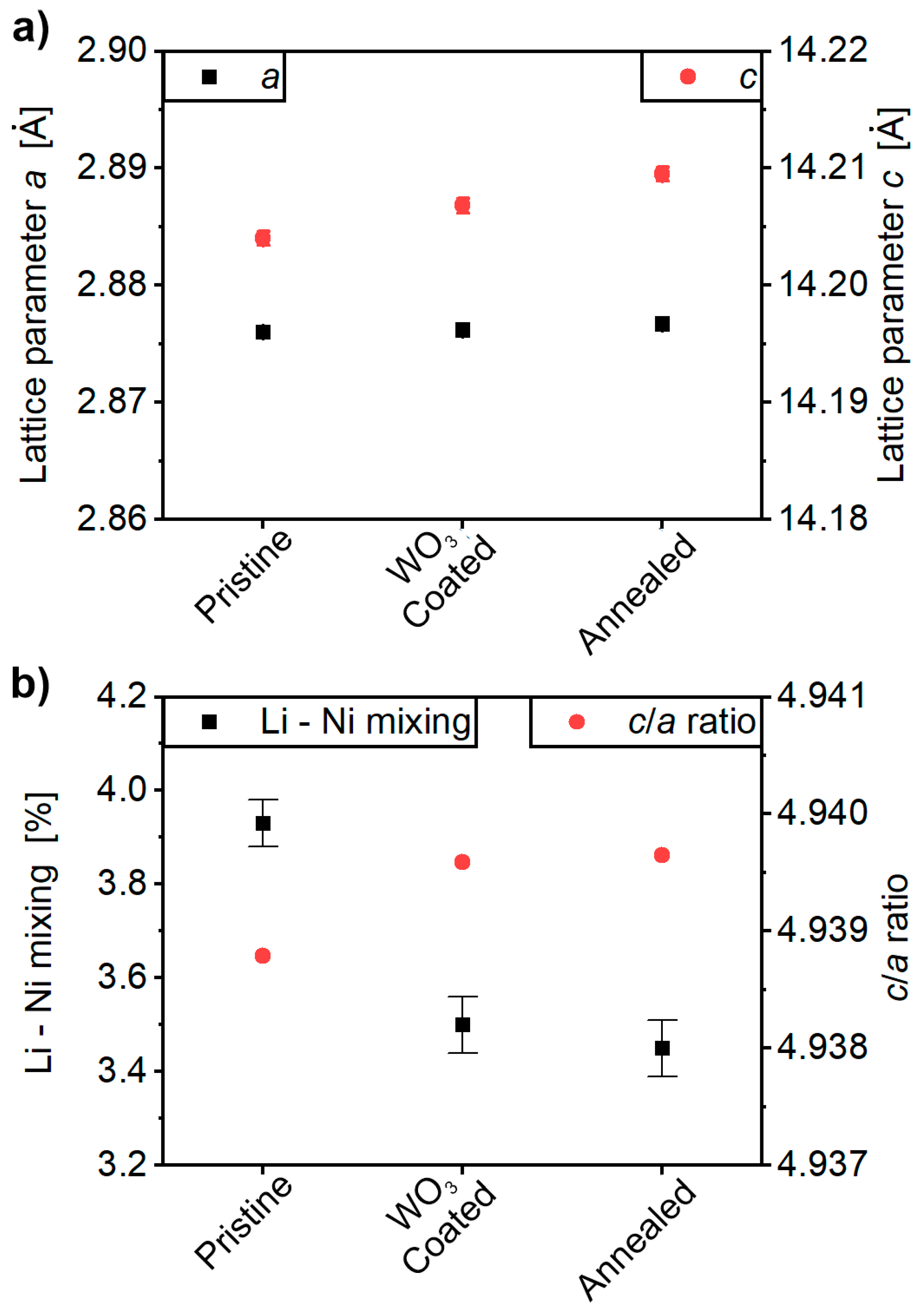
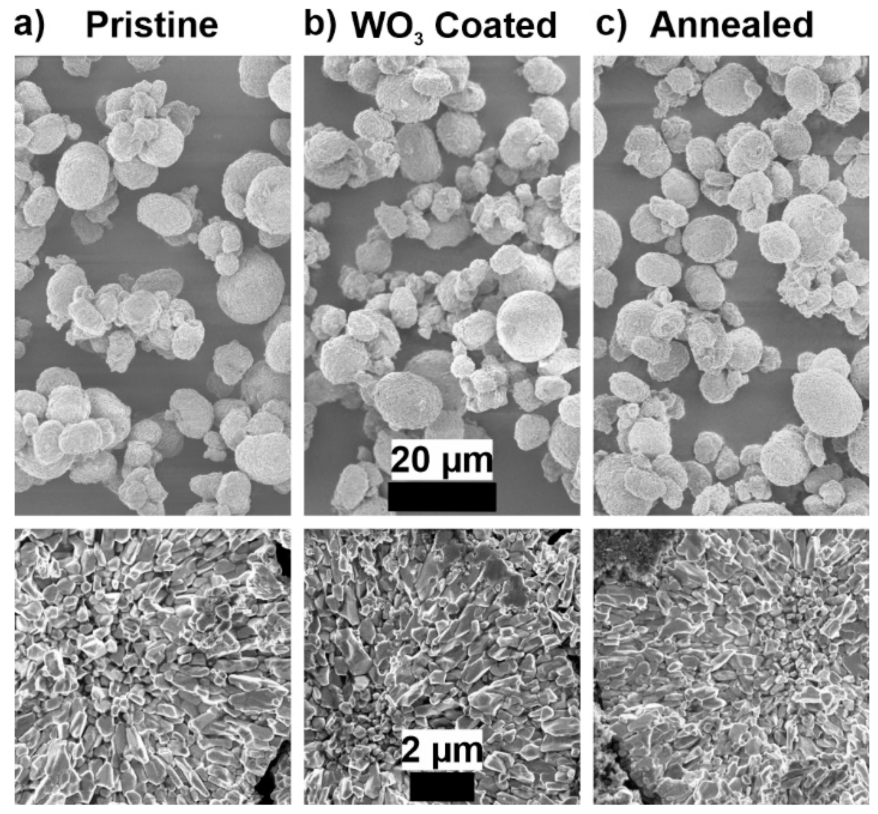
2.1. Characterization of the Cathode-Active Materials (CAMs)

Pristine NCM900505 was surface coated with WO3 (1 wt.%) via a simple sol–gel approach in isopropanol and subsequent annealing at 450 °C in pure oxygen atmosphere. This sample will be further referred to as “WO3 coated”. An annealed reference sample without coating precursor undergoing the same solvent treatment in isopropanol and subsequent annealing at 450 °C in oxygen was synthetized (further referred to as “annealed”) to investigate the influence of the process itself. The obtained powders were characterized via synchrotron XRD measurements at room temperature. The detailed diffractograms can be found in Figure S1. Tables S1 and S2 display the detailed results of the Rietveld refinements. Due to the good quality of the data, a reflection asymmetry could be found and multiple layered NCM phases were needed to obtain a good fit. This reflection asymmetry indicates small concentration gradients throughout the material as previously reported by Binder et al. [61]. The following discussion will only treat the main phase making up for about 70% of the material.
As can be seen in Figure 1a, the a lattice parameter of the investigated NCM materials only undergoes negligible changes, while the c lattice parameter is slightly increased after the treatment. However, this increase is higher for the annealed sample than for the WO3-coated materials, thus, indicating larger changes in the bulk structure if no coating is present. Figure 1b indicates that the change in the c/a ratio seems to be more related to the annealing step than to the coating. The degree of Li–Ni-mixing is decreased from 3.9% to 3.5% after the heat treatment. Up to 3% impurities (e.g., Li2CO3 and Li2SO4) could be found in the high-quality data for all samples, which could not be detected by standard laboratory X-ray diffraction. It is expected that Li2CO3 originated from contact of the CAMs to ambient air and CO2 during sample handling, while Li2SO4 is the result of the residual sulfur content in the hydroxide precursor after the co-precipitation process using transition metal sulfate feeds. The WO3-coated sample additionally showed minor Li2W2O7 and Li2WO4 hydrate impurities, which might be situated at the surface of the secondary particles. The presence of those multiple Li-W-O phases can be explained due to the presence of Li residues on the surface of the pristine material. The Li residues might be incorporated in the coating during the coating process and, hence, cleaning the surface and mitigating the negative effect they can have during charge/discharge cycling.
All cathode powders were analyzed via SEM to verify that the materials did not undergo changes in primary and secondary particle morphology. Top-view and cross-sectional SEM images are shown in Figure 2 and confirm that neither the WO3-coated, nor the annealed sample show any changes in particle morphology. Changes in performance should therefore mainly result from surface changes and the above-mentioned slight changes in the crystal structure.

2.2. Characterization of the Coating Surface Coverage on the CAM

LEIS measurements were performed on all CAM powders. This method gives information on the elemental composition of the topmost atomic layer of a sample with only a minor impact of rough surfaces and is therefore ideal to analyze coatings on the surface of CAM powders and even allows for a quantitative estimation of the surface coverage [58]. It is the only method able to do so for rough surfaces and a large enough quantity of powder to obtain good statistics. A LEIS spectrum shows two different types of information. The peaks in the spectrum represent the composition of the surface (outermost 1 atomic layer) of the sample. They are often referred to as “surface peaks”, or “single scattering peaks”. The backgrounds on the low-energy side of the peak represent the presence of the element below the surface [62,63]. This background in the present LEIS results compared to an exemplary NCM532 sample as shown in Figure S2a suggest that the pristine powder has a quite thick Li2CO3/LiOH surface layer (around 1.8 nm) which is removed for the annealed reference sample. As shown in Figure S2, the surface of the WO3-coated sample clearly shows a W signal proving a successful coating. The surface coverage or layer closure can be estimated compared to the annealed sample, indicating a surface coverage of ≈19%. The surface coverage is estimated by the difference in intensity of the Ni/Co and Mn peaks which is shown in Figure S2c. The pristine sample is covered in the above-mentioned thick layer of surface residues, while the annealed sample shows the highest Ni/Co and Mn signals. The difference between the Ni/Co signal of the annealed sample and the WO3-coated sample are about −19% which results from the tungsten coating as indicated by the clear tungsten signal (Figure S2d). To the best of our knowledge, this is the first time a quantitative surface coverage for a coating applied on CAM via a sol–gel process has been confirmed by analysis. The obtained value opens a question on the function of coatings in terms of shielding the active material from the electrolyte. The coating procedure has been applied before by Becker et al. [38] with equally positive improvements in electrochemical performance as in this study (see below), and the positive impact of the coating was primarily assigned to protection of the particle surface. This raises the question whether a more complete coating (better surface coverage) would lead to even improved results, or if the mechanism of the influence of surface coatings needs to be re-evaluated. The example of Hoskins et al. showed that there is an optimum surface coverage in terms of cycling performance [59].

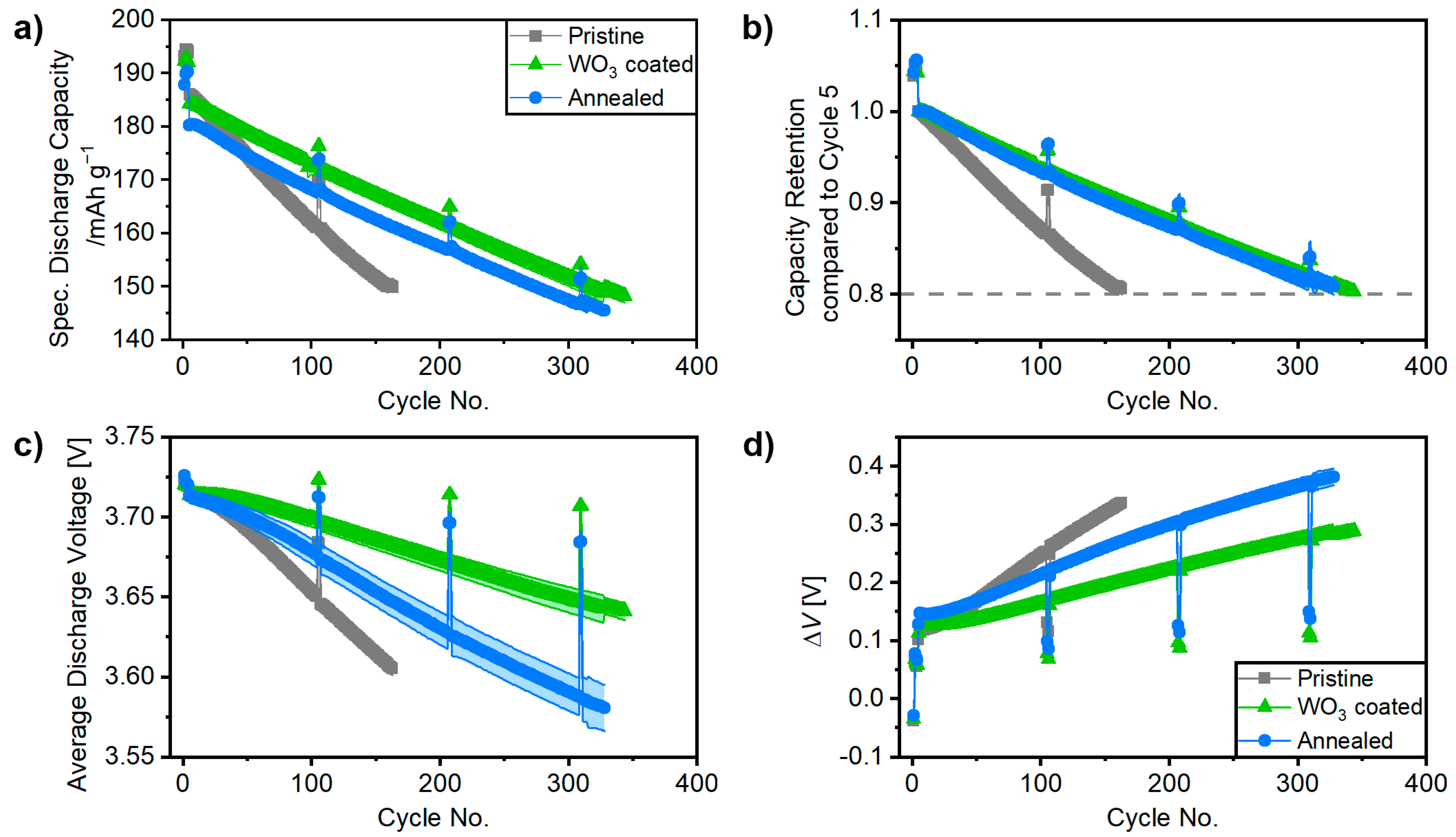
2.3. Electrochemical Charge/Discharge Cycling in Lithium Battery Cells

Two different electrochemical characterizations were carried out with electrodes produced from all three CAM powders. The rate capability was studied in NCM||Li-metal cells to avoid plating of Li metal on the graphite electrode [64] and to separate the influence of the negative electrode material on the overall performance. To minimize inhomogeneous Li-metal plating on the Li-metal anode (e.g., formation of dendritic lithium [65] taking place in organic carbonate electrolytes [66]), the C rate was only varied upon discharge while it was kept constant at 0.2 C during charge. The results of the rate-capability tests are presented in Figure S3. The rate capability of the WO3-coated sample is comparable to the pristine sample but with an improved capacity retention. The annealed material shows slightly lower initial specific capacities as well as a worse rate capability, which might originate from a different surface layer.
NCM||graphite cells were used for long-term charge/discharge cycling until 80% state of health (SOH). (SOH with reference to cycle 5, corresponding to the first discharge capacity at a rate of 0.33 C.) To allow for a reliable comparison between datasets, four formation cycles were performed at 0.1 C (=19 mA g−1) [67], while the following long-term charge/discharge studies took place at 0.33 C with two recovery cycles at 0.1 C, each with 100 cycles. The initial Coulombic efficiencies (CEff), the initial discharge capacities at 0.1 C and 0.33 C as well as the cycle in which the end-of-life criterion of 80% SOH were reached are noted in Table S3. Figure 3 shows a graphical representation of cycling results versus cycle number such as (a) specific discharge capacity, (b) capacity retention, (c) average discharge voltage, and (d) the difference between the average charge and the average discharge voltages (ΔV).
The first cycle CEff for the full cells using the pristine and the coated materials are at almost 86% while it is at only 84% for the cells using the annealed sample. This could result from a minor loss of Li+ during the modification process or changes in the Li+ kinetics. The CEff of all cells during long-term cycling was above 99.99%. The initial discharge capacities at 0.1 C vary only slightly between almost 194 mAh g−1 for cells using the pristine sample, 192 mAh g−1 for the WO3-coated sample and 190 mAh g−1 for the annealed sample. Due to the better rate capability of both the WO3-coated and pristine sample, the capacity gap increases slightly for a C rate of 0.33 C. Regarding the capacity retention, the cells based on the pristine sample show a relatively poor performance and reach 80% SOH after only 163 cycles. This lifetime is doubled for the cells using both the annealed and coated samples, indicating that a removal of the Li2CO3/LiOH surface impurities of the pristine sample alone has a beneficial effect as previously indicated [68,69,70,71].
Figure 3c shows the average discharge voltages, which play a key role for the energy density of a cell, and the specific capacities. While full cells with pristine CAM material exhibit the strongest decay, cells using the annealed sample with less surface impurities due to thermally induced surface reconstruction show slightly improved performance. The highest average discharge voltages can be observed for the cells based on the WO3-coated material, which might be related to improved kinetics at the surface due to the coating with the Li-W-O phases. This is also supported by the difference between charge and discharge voltage (∆V) in Figure 3d, being an indication for the polarization growth and impedance of the cell. This polarization growth is significantly lower for the cells with the WO3-coated sample. Figure S4 displays SEM images of the cathodes of all materials before and after cycling to 80% SOH; however, no significant changes or differences could be observed.

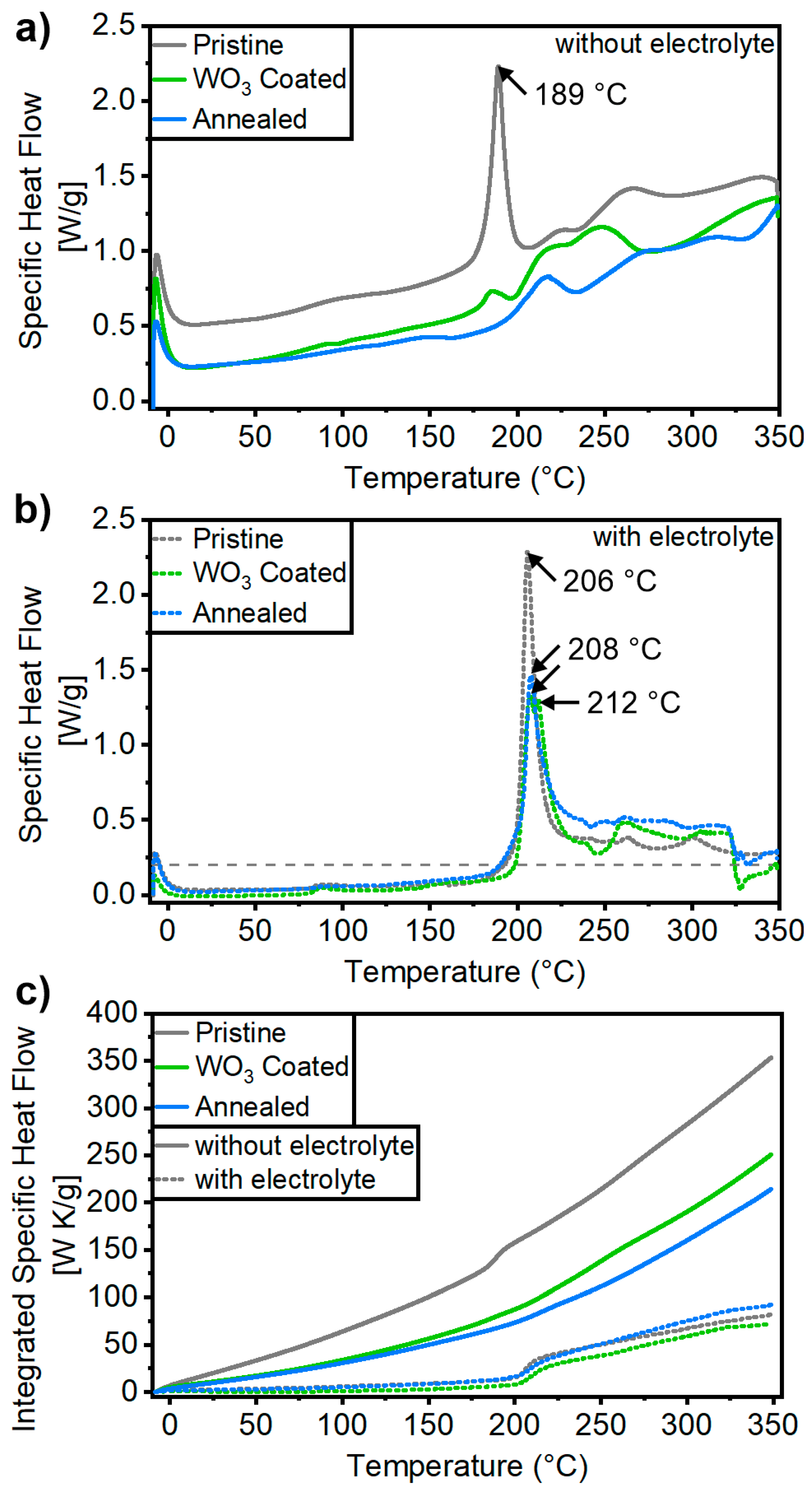
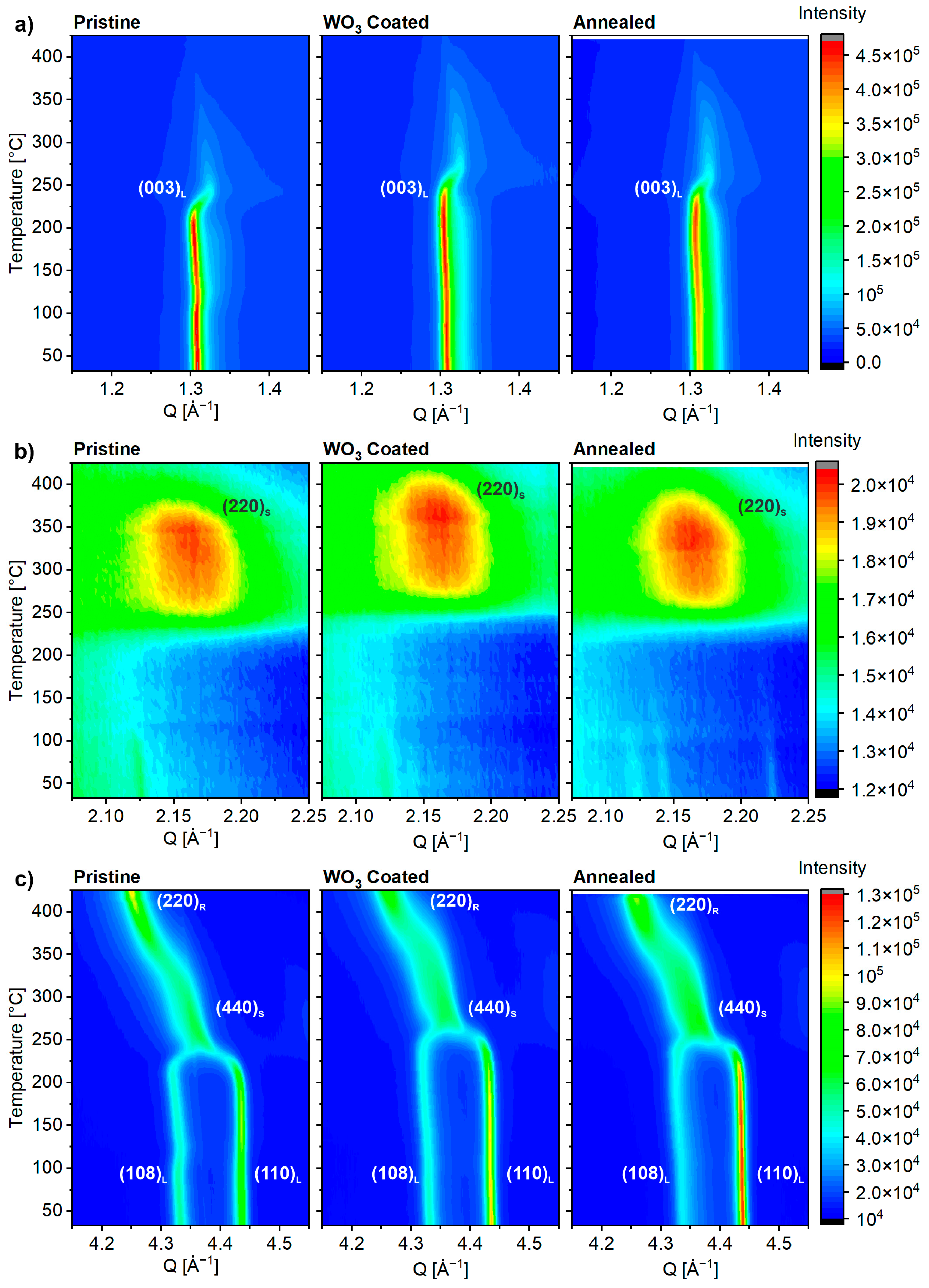
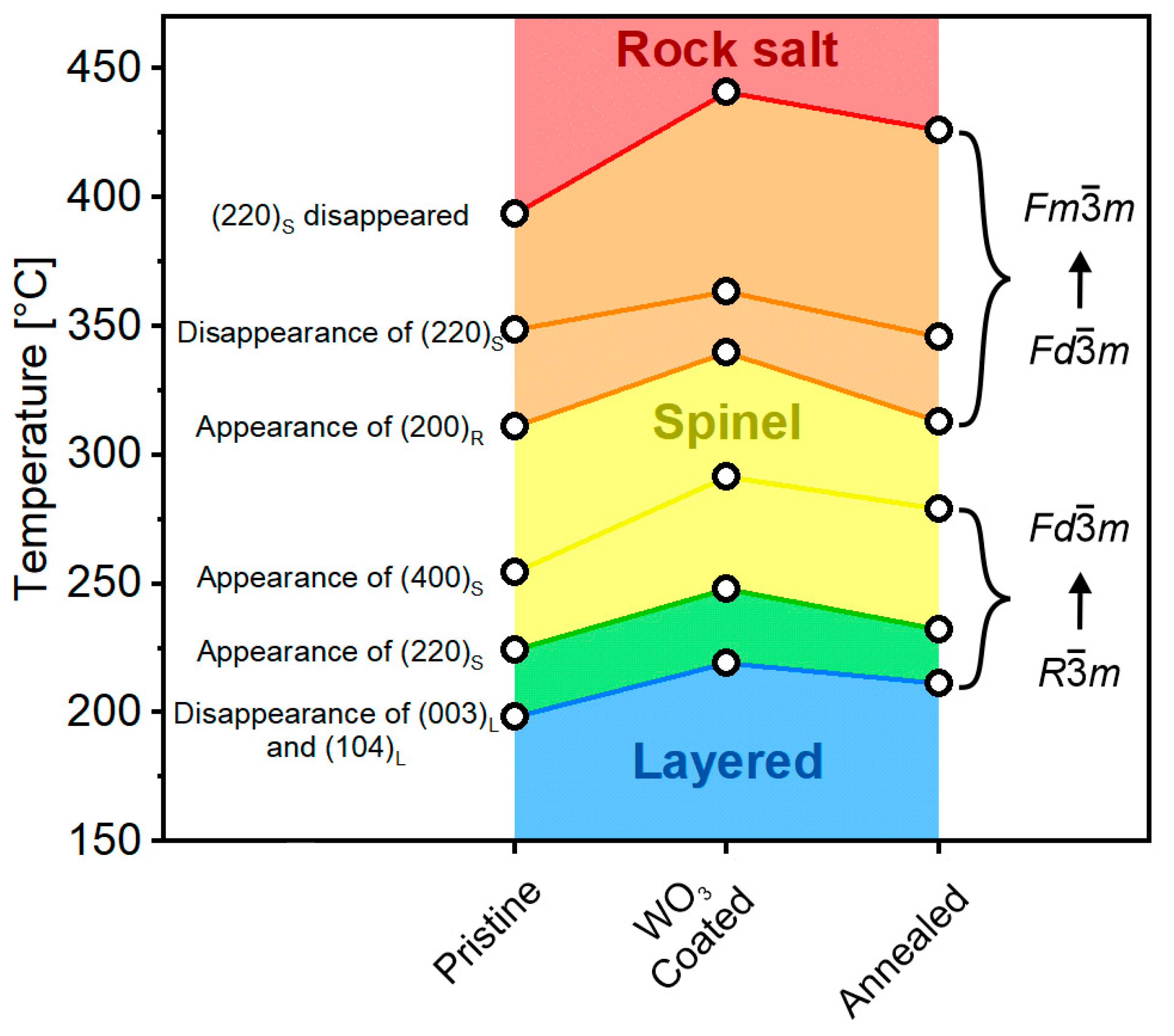
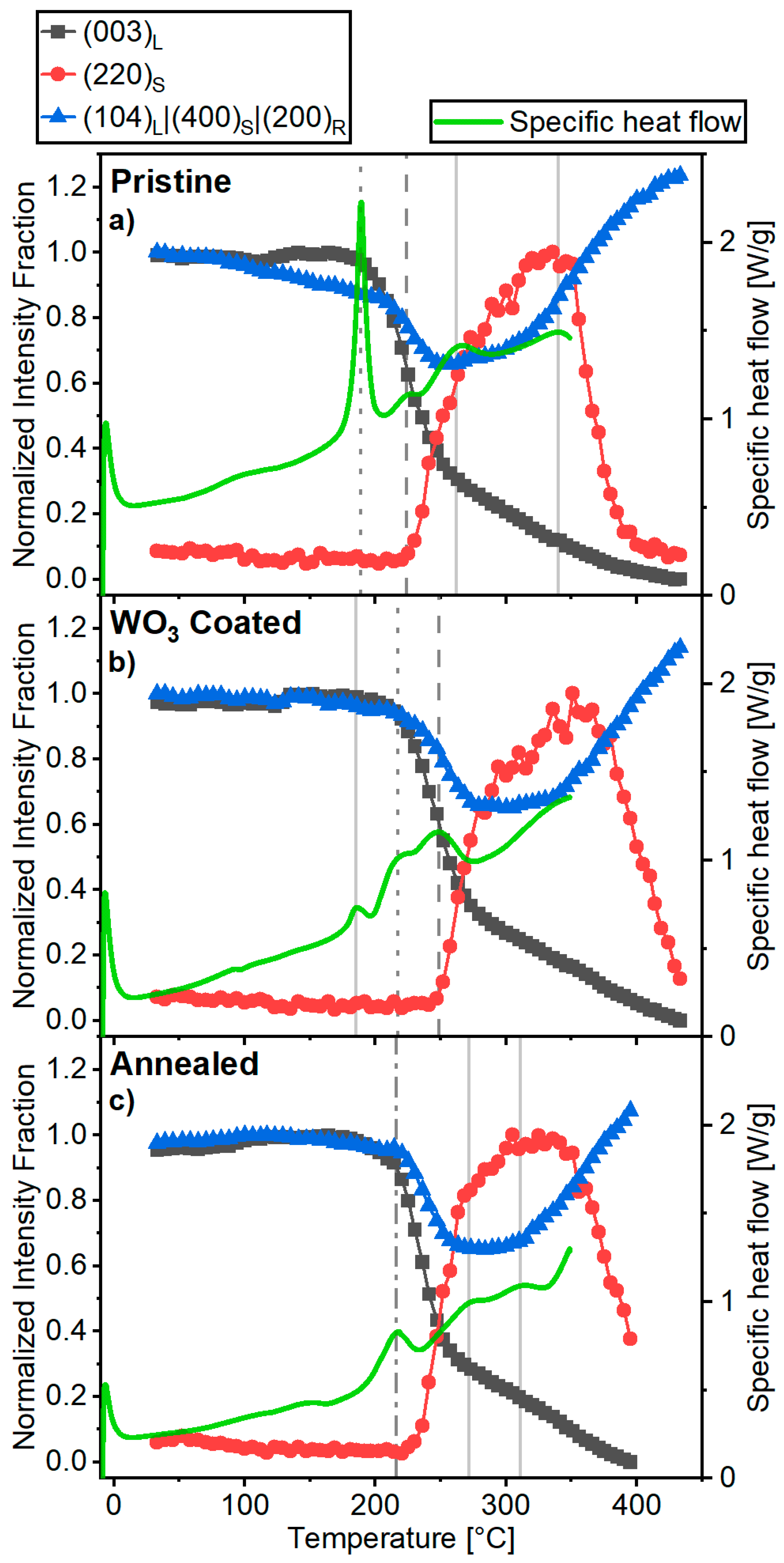
2.4. Thermal Stability of Delithiated Materials

NCM||graphite full cells were charged to a specific capacity of 190 mAh·g−1, which corresponds to the same state of charge and degree of delithiation (≈68% based on the theoretical capacity of 278 mAh g−1 for NCM) for a fair comparison. Therefore, all cathode materials were delithiated to a theoretical composition of Li0.31Ni0.90Co0.05Mn0.05O2 (= 1 C) after the formation cycles and were afterwards investigated regarding their thermal stability (see experimental part for details about sample preparation). Cells were disassembled and the electrodes were scratched off the current collector and measured by DSC. The results of the DSC measurements are shown in Figure 4 and Table 1 as well as in Tables S4 and S5. As expected, there are significant differences between the samples measured with fresh electrolyte and without electrolyte [72,73]. The pristine sample without electrolyte has a very pronounced peak at 189 °C in the specific heat flow, which disappears for the WO3-coated and the annealed samples (as discussed further in Section 3). This also results in a decrease in the integrated heat flow by 29% and 39% as shown in Figure 4c and Table S4.
All delithiated materials heated with the addition of battery electrolyte show exothermic peaks in the specific heat flow curve that might originate from the electrolyte [72]. The peak at 206 °C for the pristine material is shifted to 212 °C for the annealed sample and shifted and split to 208 °C and 212 °C for the WO3-coated sample, as shown in Figure 4b. In addition, the peak maximum is also significantly lower for both treated samples. Another indication is the onset temperature where the specific heat flow exceeds, e.g., 0.2 W g−1. Those onset temperatures are noted in Table 1. and show a small shift towards lower temperatures for the annealed sample, but a more significant shift to higher temperatures for the WO3-coated sample. The integrated heat flow in Figure 4c for the samples measured with electrolyte shows a reduction for the WO3-coated sample, while it displays an increase for the annealed sample. The WO3-coated sample can therefore be regarded as the safest CAM of this study in terms of thermal stability during DSC measurements.
In addition, the structural changes occurring during thermal decomposition of the delithiated materials were investigated via high-temperature synchrotron XRD (30–440 °C). The crystal structures that play a role during the phase transitions of the thermal decomposition are the layered, the spinel, and the rock salt phase. Their crystal structures are shown in Figure S8 and have the same oxygen sublattice. Those phase transitions at high temperatures are important because both transitions (layered to spinel and spinel to rock salt modification) are accompanied by an oxygen release and it is important to elucidate if there are changes in phase transitions when applying surface coatings to the cathode material [11]. This oxygen release is a severe safety risk, as oxygen can accelerate a fire [74]. The summarized results are shown in Figure 5 and Figure 6, while the full patterns are displayed in Figures S5–S7.
Figure 5 shows major reflections that are helpful to monitor the disappearance and appearance of the relevant phases. The letters in subscript behind the given Miller indices of each reflection stand for the respective phases (L = layered; S = spinel; R = rock salt). The selected reflection evolutions are (a) the disappearance of (003)L, (b) the appearance and disappearance of (220)s, and (c) the transformation from (108)L/(110)L via (440)S to (220)R. To monitor the evolution of the reflections quantitatively, the areas of all reflections were calculated numerically, and the results are shown in Figure S9. It must be noted that the integral of the (003)L region also includes the area of the background bump from the quartz capillary. Therefore, the intensity of the last diffractogram was subtracted from all the previous ones for a better representation of the phase evolution of the (003)L reflection in Figure 7. As apparent by the diffraction pattern in Figure 5, the disappearance of the reflections of the layered structure as well as the appearance of the spinels and the rock salt reflections is shifted to higher temperatures, especially for the WO3-coated sample.
To determine the temperatures where phase transitions occur, the turning points of phase disappearances and appearances were determined as intersections of the respective linear fits of the regions before and after each turning point. The results are shown in Figure 6 and reveal a slight shift in the critical phase transitions to higher temperatures for the annealed material and a more pronounced shift for the WO3-coated material. This indicates that simple surface modifications can already delay the phase transformation and, hence, the oxygen release to higher temperatures. For the WO3-coated sample, this temperature difference compared to the pristine material can range from 20 °C for the layered-to-spinel phase transition to 40 °C for the spinel to rock salt phase transition. The strong influence of the surface modifications on the thermal stability is in accordance with investigations from Nam et al. who proposed that the thermal decomposition occurs from the particle surface to the core [75]. Therefore, the presence of a coating on the surface of the particles, even if it only leads to a surface coverage of 19% according to LEIS measurements, is expected to delay the thermal runaway.

3. Discussion

Overall, no significant changes in the bulk properties can be observed after surface modification. Lattice parameters and Li-Ni-mixing are similar for both treated (WO3 coated and annealed) samples. In addition, there is no change in the primary or secondary particle morphology compared to the pristine material. This suggests that improvements in terms of capacity retention during charge/discharge cycling and thermal stability mostly originate from the surface modifications, such as “cleaning” Li impurities and ceramic coating. However, the initial capacity of cells using the WO3-coated material is slightly higher than for the annealed material. This suggests that the coating might prevent Li loss, for example, during the annealing steps and/or improve Li kinetics at the surface.
To link thermal decomposition to the structural changes, the DSC data were plotted with the phase evolution as obtained from in situ synchrotron XRD data versus the temperature, as illustrated in Figure 7. Most DSC peaks can be linked to the disappearance or appearance of a phase observed in the synchrotron data. The only exception is the first small bump in the DSC data of the WO3-coated material, which might be related to the coating itself. In general, a large heat flow (corresponding to an intense peak in the DSC results) can be mitigated for the surface-treated samples. Furthermore, there is always one DSC peak or a small bump at the temperature where the layered reflection starts to fade and the spinel reflection starts to occur. This also corresponds to the first incidence of oxygen loss during the transformation to the spinel phase as reported by Bak et al. [11]. The strong exothermic peak at 189 °C of the pristine sample, for example, which is significantly decreased for the surface-modified samples, correlates to the start of the disappearance of the layered phase. For the surface-modified samples, the corresponding peaks in the DSC results are less pronounced and shifted to higher temperatures. Additional DSC peaks mostly correlate with the regions where either the spinel reflection disappears, or the rock salt phase emerges. This corresponds to the next phase transition that results in oxygen loss. While most phase transitions for all materials are accompanied by thermal decomposition and oxygen release, the specific heat flow is significantly lower for both the WO3-coated and annealed samples than for the pristine sample.

4. Conclusions

In this study, the impact of a surface coating on thermal stability and electrochemical properties on NCM900505 was deeply investigated. Both the WO3-coated and annealed NCM900505 cathode materials exhibit slightly higher lattice parameters and a lower Li–Ni mixing, but the change for the annealed sample is larger. LEIS measurements prove that the surface modifications are successful. The WO3-coated cathode material shows a W signal on the surface, while the surface of the annealed sample is “cleaned” from a significant amount of surface residues, such as LiOH and Li2CO3. With regard to the surface coverage of the WO3 coating, the LEIS results indicate a surface coverage of roughly 20%, which corresponds to the surface coverage. To our knowledge, this is the first time the surface coverage for a sol–gel-type coating is quantified within a scientific study and with regard to the whole powder and not only on the surface of selected particles. It is remarkable that even such an incomplete surface coating can result in such a significant shift in the decomposition temperatures (20–40 °C) without obvious changes in the primary or secondary particle morphology.
The electrochemical performance with respect to rate capability is negatively impacted by the annealing step, but this can be mitigated by the WO3 coating. In long-term charge/discharge cycling studies in NCM||graphite cells, both modified samples showed significantly improved performance. While both the WO3-coated and annealed samples show similar capacity retention, the WO3-coated sample shows a higher initial discharge capacity, a higher average discharge voltage, and a lower polarization growth.
During calorimetric investigations of the delithiated materials, a lower overall heat flow and a mitigation of pronounced peaks can be observed for the modified materials without electrolyte. With fresh electrolyte, a later onset temperature for the WO3-coated sample and later peak maxima for both the WO3-coated and annealed samples can be observed. High-temperature synchrotron XRD investigations show that both surface modifications lead to a shift in the detrimental phase transitions (layered to spinel and rock salt) to higher temperatures. This effect is especially pronounced for the WO3-coated sample. Hence, surface-treated materials still exhibit phase transitions and thermal decomposition, but with a lower specific heat flow and at higher onset temperatures, which in turn result in improved safety.
It can be concluded that a WO3 coating as surface modification can successfully improve cycling properties and the stability of the delithiated materials with a surface coverage of only 20%. It would therefore be interesting to investigate higher amounts of surface coverage with respect to thermal and cycling stabilities in future works.

5. Experimental Section

Material preparation: The synthesis of the Ni-rich hydroxide precursors was carried out in 1 L CTFR (Continuous Taylor Flow Reactor, Tera 3300, Laminar Co. Ltd., Seongnam-si, Republic of Korea) by a continuous co-precipitation process using a, as previously reported [32]. For experimental details of the co-precipitation of the Ni0.90Co0.05Mn0.05(OH)2 precursors, please refer to Gomez-Martin et al. [32].
For the lithiation of the Ni0.90Co0.05Mn0.05(OH)2 precursors, they were mixed homogeneously with LiOH·H2O (98 %, Fisher Chemical, Hampton, NH, USA), and homogenized by mortar and pestle. A lithium/TM molar ratio of 1.02 (Li:(Ni:Co:Mn) of 1.02:1) was used and a total mass of approximately 200 g was targeted. The lithium excess was used to compensate for lithium losses during calcination and prevent lithium deficiency in the product after synthesis. The calcination of the powder mixtures was carried out in a muffle furnace (Nabertherm GmbH (Lilienthal, Germany), equipped with a gas control unit) for 3 h at 480 °C and then for 12 h at 750 °C under pure oxygen atmosphere. A heating rate of 2 °C min−1 was used for all heating periods and an oxygen flow of 50 L h−1 was used during the whole calcination process. The cooling rate was not controlled and hence resulted from natural cooling of the kiln.
The cathode-active material for coating investigations was thus the obtained LiNi0.90Co0.05Mn0.05O2 (NCM900505). As coating precursor, ammonium tungstate ((NH4)10H2(W2O7)6, 99.99%, Sigma-Aldrich, St. Louis, MO, USA) was used for tungsten trioxide (WO3). The purity of the pristine precursor material was verified by PXRD. A schematic illustration of the synthesis conditions can be found in Figure 8. To coat the cathode material, the coating precursor (stoichiometric amounts to achieve a coating of 1 wt.%) was dissolved in isopropanol. Distribution of the coating precursor in the isopropanol was achieved by stirring of the mixture with a magnetic stirrer for ≈1 h at 50 °C. After this period, the active material was added to obtain a solid content of ≈40%. The obtained dispersion was stirred at 50 °C for 16 h. Afterwards, the solvent was evaporated at 60 °C under reduced pressure using a Büchi rotary evaporator. The obtained powder was then calcined under a pure oxygen atmosphere using a muffle furnace (Nabertherm GmbH) at 450 °C for 12 h. The heating rate was set to 5 °C min−1. The cooling rate was not controlled and hence resulted from natural cooling of the kiln. The resulting product was hand-ground with a mortar and pestle for homogenization before further processing. The presence of tungsten on the sample surface was confirmed via LEIS. To study the effect of the surface treatment alone, a reference sample (“annealed”) was prepared. This sample underwent the same solvent treatment followed by drying under reduced pressure and calcination as for the WO3-coated samples but no coating was applied.
Materials characterization: Synchrotron powder X-ray diffraction (PXRD) experiments were performed at the Material Science Powder Diffraction (BL04-MSPD) beamline of the ALBA-CELLS synchrotron [76]. Experiments were carried out with a wavelength of λ = 0.4142 Å (calibrated using a Si NIST standard) using an Si 111 monochromator and an array of MYTHEN position-sensitive detectors. For measurements at room temperature, samples were filled in 0.7 mm borosilicate glass capillaries, which were hermetically sealed and mounted on a spinning sample holder. Data were collected in Debye–Scherrer geometry for 27 different positions of the detector spanning an angular range of 0.3759°–62.1459° in 2θ and a long data acquisition time of 30 s was chosen for each position to obtain high-intensity patterns. Rietveld refinements [77] were carried out with Topas Academic V6 (Bruker AXS GmbH) based on a α-NaFeO2 structure with space group R 3 ¯ m. The fundamental parameters approach was used for peak fitting [78]. Li was assumed to occupy 3a sites, and the 3b sites were assumed to be filled with Ni, Co, and Mn. Additional constraints were used to refine Ni moving from the 3b site to the 3a site and at the same time, Li moving from the 3a site to the 3b site to account for Li–Ni mixing.
High-temperature measurements were carried out in quartz glass capillaries of 1 mm outer and 0.5 mm inner diameters, open on both ends under constant Ar flow by using the ITQ-ALBA capillary flow reaction cell [79] and a hot-air blower from room temperature to 400 °C at a heating rate of 5 °C min−1. The powder was held back by quartz wool on both ends. Temperature calibration was performed by directly measuring the temperature at the sample position by an independent K-type thermocouple. Real temperature was measured for hot blower readings from 50 to 950 °C with 50 °C steps. The calibration data were additionally cross-checked by observing several phase transitions: Na2CO3 monoclinic to hexagonal (483 °C), Na2CO3 melting (851 °C), SiO2 alpha to beta (573 °C), and NaCl melting (801 °C). In all cases, a series of in situ diffraction patterns was collected around phase transition temperature with a heating rate of 2 °C min−1 and measurement time of 30 s/pattern.
The particle morphology of the cathode materials was investigated by scanning electron microscopy (SEM) using a Carl Zeiss AURIGA field emission microscope with a Schottky field emitter as electron source. The typical accelerating voltage was 3 kV. For post-mortem analysis, NCM||graphite cells were disassembled after reaching 80% SOH in the discharged state at 2.8 V. To prepare for analysis, the cathode surfaces were cleaned by rinsing with 200 μL of ethyl methyl carbonate (EMC, BASF SE) inside an argon-filled glove box to eliminate salt impurities. Subsequently, the electrodes were dried under reduced pressure and then transferred into the SEM using a vacuum-sealed sample holder to prevent exposure to atmospheric air.
Low-energy ion scattering (LEIS) measurements were performed by the Tascon GmbH. In a LEIS experiment, light noble gas primary ions scatter from the atoms on and in the sample. The scattering does not exclusively occur with surface atoms. LEIS owes its single atomic layer surface specificity to the use of noble gas ions, combined with electrostatic energy analyzers. The electrostatic energy analyzer makes sure that only ions are detected. The use of noble gas primary ions makes sure that the primary particles are neutralized as soon as they enter the sample and, therefore, cannot be detected anymore. Some of the neutrals that enter the sample scatter form atoms in deeper layers and some of these leave the sample again. A very small fraction of these neutrals is re-ionized as they leave the surface and can be detected. This fraction is much smaller than the survival fraction for an ion scattering from a surface atom, and therefore, their intensity is relatively small. Since these re-ionized noble gas particles have lost energy (through stopping) while traveling through the sample, they show up as a background on the low-energy side of the surface peak. The re-ionization probability is small enough that it does not interfere with the evaluation of the surface peak, but it is large enough, in particular for He scattering from oxidic samples, to allow for an evaluation of these backgrounds. The information is then similar to that of RBS (Rutherford Backscattering Spectroscopy): the intensity axis corresponds to the concentration of the element and the energy axis corresponds to a depth scale. LEIS analysis was performed with a Qtac100 LEIS spectrometer (IONTOF GmbH, Münster, Germany), equipped with a double toroidal analyzer. This instrument analyzes ions scattered at a scattering angle of 145°, collecting a signal from all azimuth angles. As primary ions, 3 keV 4He+ (for an overview of all elements from C and heavier) and 5 keV 20Ne+ (for improved resolution and sensitivity for heavier elements) were used. The samples were prepared by placing the powders in a sample cup and gently compacting them before transferring them to the instrument and pumping down. Due to contact with air, most samples are adsorbing hydrocarbons from air. In addition, mixed oxides containing Li form a Li2CO3 film. Therefore, prior to the analysis, the samples were treated in situ with thermal O atoms, to remove adsorbed hydrocarbons. In addition, the samples were sputtered with a dose of 1 × 10¹⁵ 5 keV 20Ne+ ions/cm2, from the primary ion source. This sputter treatment preferentially removes Li2CO3 from the surface, while limiting the damage to heavier oxides. The 3 keV 4He+ spectra were recorded with a primary ion dose of 1.4 × 10¹⁴ ions/cm2. The 5 keV 20Ne+ spectra were recorded by adding 10 spectra, each with a primary ion dose of 2.8 × 10¹³ ions/cm2.
The thermal stability of the respective cathode materials in their delithiated (i.e., charged) state was evaluated via DSC (Q2000, TA Instruments, New Castle, DE, USA). NMC||graphite full cells were cycled for three formation cycles within the cell voltage range of 2.8–4.2 V, and then charged until the cathodes achieved a capacity of 190 mAh g−1 for a fair comparison and identical de-lithiation degree. The cells were then disassembled in the dry room and rinsed with 300 μL dimethyl carbonate (DMC) to remove residual salt. The cathode was then dried and sealed tightly in a 100 μL high-pressure stainless-steel pan with a gold-plated copper seal with or without 7 μL of fresh electrolyte (1 M LiPF6 in 3:7 vol% EC/EMC + 2 wt% VC, Solvionic, Toulouse, France). The studies were conducted from 30 to 350 °C with a 5 °C min−1 heating rate under argon atmosphere.
Electrode preparation: Electrode preparation and drying of the positive electrodes (cathodes) was carried out as described in our previous work [39]. Cathodes had an average active material mass loading of (i) ≈5.0 ± 0.2 mg cm−2 (investigations in NCM||Li-metal cells) and (ii) 12.0 ± 0.5 mg cm−2 (investigations in NCM||graphite full cells). The resulting areal capacities were (i) 0.95 ± 0.4 mAh cm−2 and (ii) 2.3 ± 0.1 mAh cm−2, respectively, as obtained from the 2nd cycle discharge capacity from NCM||Li-metal cells (at =19 mA g−1, 2.9–4.3 V).
Electrode preparation and drying of the negative electrodes (anodes) used for NCM||graphite full cell investigations was carried out by the in-house battery line as described in our previous work [80]. The negative electrodes had an average active mass loading of ≈7 ± 1 mg cm−2 (≈2.5 ± 0.3 mAh cm−2 areal capacity) based on the practical capacity (≈350 mAh g−1) of graphite obtained from the 2nd cycle discharge capacity from graphite||Li-metal cells.
Cell assembly and electrochemical characterization. Electrochemical investigations were carried out in a two-electrode configuration in coin cells (CR2032, Hohsen Corporation). Two types of cells of the Ni-rich cathode materials were assembled in a dry room atmosphere with a dew point of at least −50 °C (relative humidity of 0.16%). The electrolyte used for both consisted of 1 M LiPF6 in 3:7 vol.% EC:EMC (Solvionic) with 2 wt.% vinylene carbonate (VC, 99.9%) as a solid electrolyte interphase (SEI) additive. The separator (1- layer, 16 mm Ø, Celgard 2500, Celgard, Charlotte, NC, USA) was wetted with 35 μL of electrolyte. For C-rate investigations, NCM||Li-metal cells were used. Long-term cycling stability was investigated in NCM||graphite full cells. To ensure a high reproducibility, we assembled a minimum of three cells per sample. Error bars in the corresponding figures represent the standard deviation between three cells.
For the investigation in NCM||Li-metal cells, a positive electrode (Ø14 mm; 0.95 ± 0.4 mAh cm−2) and a Li-metal negative electrode (Ø15 mm, lithium metal foil, 500 µm; battery grade: purity ≥ 99.9%, China Energy Lithium (CEL Co.)) were used. For NCM||graphite full cell investigations, graphite was used as negative electrode (Ø15 mm) to pair the positive electrode (Ø14 mm; 2.3 ± 0.1 mAh cm−2). A ratio of 1.15:1.00 was used as negative/ positive (N/P) capacity balancing calculated with data from the 2nd cycle discharge capacities from the Li-metal cell investigations.
A Maccor Series 4000 battery tester (Maccor, Inc., Tulsa, OK, USA) was used for electrochemical cycling. The cycling was carried out at 20 °C for all cell types. At a rate of 1 C, 190 mA g−1 was defined as the specific current. For rate capability tests a constant current (CC) charge/discharge cycling in NCM||Li-metal cells was used. The cycling procedure started with a 6 h step at open-circuit voltage (OCV) followed by two formation cycles at 0.1 C. Afterwards, different C rates were tested with three cycles at 0.2 C, and five cycles at 0.33 C, 0.5 C, 1 C, and 3 C each. The discharge rate was limited to 0.2 C, resulting in asymmetric tests resulting in asymmetric tests for charge rates above 0.2 C. After the C-rate investigations, cells were cycled at 0.1 C for two cycles, followed by 15 cycles at 0.33 C. The cell voltage window was between 2.9 and 4.3 V.
NCM||graphite full cells were used to investigate the long-term cycling stability of the cathode materials. For this, a cell voltage range of 2.8–4.2 V vs. Li+||Li was used. The CC cycling was complemented by a constant voltage (CV) step after each charge step. The criterium for this CV step was for the specific current to fall below ≤0.05 C. Interphase formation was carried out during four cycles at 0.1 C. This was followed by cycling until reaching an 80% state of health (SOH) at 0.33 C. For capacity retention evaluation every 100th cycle, cells were cycled for two cycles at 0.1 C.

Supplementary Materials

The following supporting information can be downloaded at: https://www.mdpi.com/article/10.3390/batteries9050245/s1. Figure S1: Rietveld refinements of the NCM materials showing measured (grey), calculated (red) data as well as the difference between them (blue). Rwp, Rexp and goodness of fit (GOF) are shown as well. The inlayer shows the (108)/(110) reflections split up indicating a well-defined layered structure; Figure S2: LEIS results. (a) Comparison of 3 keV 4He+ spectra for the pristine sample and an NCM532 reference before the sputter treatment. The difference in background indicates a thick layer of surface residues. (b) 3 keV 4He+ spectra for the samples in set 2 after the sputter treatment. (c,d) 5 keV 20Ne+ spectra after background subtraction and smoothing. (c) Mn/Co/Ni region and (d) W region; Figure S3: Rate capability investigations in NCM || Li metal cells. Specific discharge capacity vs. cycle number. Cell voltage range: 2.9–4.3 V (1C = 190 mA g−1). Error bars: standard deviation of three cells for each sample. The missing data point in cycle 4 for the annealed sample resulted from a short power outage. 1 C = 190 mA g−1; Figure S4: SEM images with a magnification of 10kx of various electrodes before (left) and after (right) cycling until 80% SOH was reached; Figure S5: Diffraction pattern contour plot of the delithiated pristine material. Cathode powders in a quartz capillary were heated from room temperature to 400 °C using the ITQ-ALBA capillary flow reaction cell; Figure S6: Diffraction pattern contour plot of delithiated WO3-coated material. Cathode powders in a quartz capillary were heated from room temperature to 400 °C using the ITQ-ALBA capillary flow reaction cell; Figure S7: Diffraction patterns contour plot of delithiated annealed material. Cathode powders in a quartz capillary were heated from room temperature to 400 °C using the ITQ-ALBA capillary flow reaction cell; Figure S8: Comparison of the crystallographic structures with the different Li-Ni-O stoichiometries and a cubic close packing oxygen sublattice. Oxygen ions are displayed in red, Li ions are displayed in green and Ni ion are displayed in grey. For reasons of better visibility only Ni is shown as transition metal. Coordination spheres are shown either as transparent octahedra or tetrahedra as ball-stick model; Figure S9: Phase evolutions as derived from the disappearance and appearance of selected characteristic reflections of the layered ((003)L and (104)L), the spinel ((220)S and (400)S) and the rock salt phases (200)R; Table S1: Information on the structural parameters used for the refinement as well as introduction of the refined parameters z(O), Limix, beq(O) and beq(TM); Table S2: Results of the Rietveld refinements: R-weighted pattern (Rwp), R expected (Rexp), goodness of fit (GOF), lattice parameters a and c, unit cell volume (V), Li–Ni mixing (Limix), z-Position and isotropic thermal factors. (beq); Table S3: Results of long-term stability investigation in NCM || graphite full-cells. The given errors are the standard deviation of three cells per sample; Table S4: Results of the differential scanning calorimetry of cathode materials delithiated to Li0.31Ni0.90Co0.05Mn0.05O2. Integrated specific heat flow without and with fresh electrolyte; Table S5: Results of the differential scanning calorimetry of cathode materials delithiated to Li0.31Ni0.90Co0.05Mn0.05O2. Temperatures for the position of the first peak max and where the decomposition onset of 0.2 W g−1 for the specific heat flow is exceeded.

Author Contributions

Conceptualization, F.R. and A.G.-M.; methodology, F.R. and A.G.-M.; validation, F.R. and A.G.-M.; formal analysis, F.R. and A.G.-M.; investigation, F.R.; data curation, F.R.; writing—original draft preparation, F.R.; writing—review and editing, F.R., A.G.-M., R.S., T.J.P. and J.R.-R.; visualization, F.R.; supervision, R.S., T.J.P., J.R.-R. and M.W.; project administration, R.S., A.G.-M. and T.J.P.; funding acquisition, R.S., T.J.P., J.R.-R. and M.W. All authors have read and agreed to the published version of the manuscript.

Funding

This research was funded by the European Union through the project “SeNSE”. This project has received funding from the European Union’s Horizon 2020 research and innovation program under grant agreement No. 875548. Joaquin Ramirez-Rico acknowledges funding from Junta de Andalucía under grant no. P20-01186 (PAIDI 2020) and US-1380856 (FEDER Andalucía 2014-20). Furthermore, he wishes to thank the Spanish Ministry of Science and Innovation under Grant no. PID2019-107019RB-I00 (co-financed with FEDER funds).

Acknowledgments

The authors express their gratitude towards Tascon GmbH for carrying out the LEIS measurements and Debbie Berghus for the DSC measurements. We thank Solvionic for the supply of electrolytes. We also thank Andre Bar for his graphical support. Room and high-temperature in situ XRD experiments were carried out at the MSPD beamline at ALBA Synchrotron with the collaboration of ALBA staff.

Conflicts of Interest

The authors declare no conflict of interest.

References

  1. EUCAR. Battery Requirements for Future Automotive Applications; EUCAR: Etterbeek, Belgium, 2019. [Google Scholar]
  2. Andre, D.; Kim, S.-J.; Lamp, P.; Lux, S.F.; Maglia, F.; Paschos, O.; Stiaszny, B. Future generations of cathode materials: An automotive industry perspective. J. Mater. Chem. A 2015, 3, 6709–6732. [Google Scholar] [CrossRef]
  3. Betz, J.; Bieker, G.; Meister, P.; Placke, T.; Winter, M.; Schmuch, R. Theoretical versus Practical Energy: A Plea for More Transparency in the Energy Calculation of Different Rechargeable Battery Systems. Adv. Energy Mater. 2019, 9, 1900761. [Google Scholar] [CrossRef]
  4. Winter, M.; Barnett, B.; Xu, K. Before Li Ion Batteries. Chem. Rev. 2018, 118, 11433–11456. [Google Scholar] [CrossRef]
  5. Meister, P.; Jia, H.; Li, J.; Kloepsch, R.; Winter, M.; Placke, T. Best Practice: Performance and Cost Evaluation of Lithium Ion Battery Active Materials with Special Emphasis on Energy Efficiency. Chem. Mater. 2016, 28, 7203–7217. [Google Scholar] [CrossRef]
  6. Li, W.; Erickson, E.M.; Manthiram, A. High-nickel layered oxide cathodes for lithium-based automotive batteries. Nat. Energy 2020, 5, 26–34. [Google Scholar] [CrossRef]
  7. Myung, S.-T.; Maglia, F.; Park, K.-J.; Yoon, C.S.; Lamp, P.; Kim, S.-J.; Sun, Y.-K. Nickel-Rich Layered Cathode Materials for Automotive Lithium-Ion Batteries: Achievements and Perspectives. ACS Energy Lett. 2016, 2, 196–223. [Google Scholar] [CrossRef]
  8. Schmuch, R.; Wagner, R.; Hörpel, G.; Placke, T.; Winter, M. Performance and cost of materials for lithium-based rechargeable automotive batteries. Nat. Energy 2018, 3, 267–278. [Google Scholar] [CrossRef]
  9. Noh, H.-J.; Youn, S.; Yoon, C.S.; Sun, Y.-K. Comparison of the structural and electrochemical properties of layered Li[NixCoyMnz]O2 (x = 1/3, 0.5, 0.6, 0.7, 0.8 and 0.85) cathode material for lithium-ion batteries. J. Power Sources 2013, 233, 121–130. [Google Scholar] [CrossRef]
  10. Kasnatscheew, J.; Röser, S.; Börner, M.; Winter, M. Do Increased Ni Contents in LiNixMnyCozO2 (NMC) Electrodes Decrease Structural and Thermal Stability of Li Ion Batteries? A Thorough Look by Consideration of the Li+ Extraction Ratio. ACS Appl. Energy Mater. 2019, 2, 7733–7737. [Google Scholar] [CrossRef]
  11. Bak, S.-M.; Hu, E.; Zhou, Y.; Yu, X.; Senanayake, S.D.; Cho, S.-J.; Kim, K.-B.; Chung, K.Y.; Yang, X.-Q.; Nam, K.-W. Structural Changes and Thermal Stability of Charged LiNixMnyCozO2 Cathode Materials Studied by Combined In Situ Time-Resolved XRD and Mass Spectroscopy. ACS Appl. Mater. Interfaces 2014, 6, 22594–22601. [Google Scholar] [CrossRef]
  12. Li, T.; Yuan, X.-Z.; Zhang, L.; Song, D.; Shi, K.; Bock, C. Degradation Mechanisms and Mitigation Strategies of Nickel-Rich NMC-Based Lithium-Ion Batteries. Electrochem. Energy Rev. 2020, 3, 43–80. [Google Scholar] [CrossRef]
  13. Jung, R.; Metzger, M.; Maglia, F.; Stinner, C.; Gasteiger, H.A. Chemical versus Electrochemical Electrolyte Oxidation on NMC111, NMC622, NMC811, LNMO, and Conductive Carbon. J. Phys. Chem. Lett. 2017, 8, 4820–4825. [Google Scholar] [CrossRef]
  14. Jung, S.-K.; Gwon, H.; Hong, J.; Park, K.-Y.; Seo, D.-H.; Kim, H.; Hyun, J.; Yang, W.; Kang, K. Understanding the Degradation Mechanisms of LiNi0.5Co0.2Mn0.3O2 Cathode Material in Lithium Ion Batteries. Adv. Energy Mater. 2014, 4, 1300787. [Google Scholar] [CrossRef]
  15. Zheng, S.; Hong, C.; Guan, X.; Xiang, Y.; Liu, X.; Xu, G.L.; Liu, R.; Zhong, G.; Zheng, F.; Li, Y.; et al. Correlation between long range and local structural changes in Ni-rich layered materials during charge and discharge process. J. Power Sources 2019, 412, 336–343. [Google Scholar] [CrossRef]
  16. Klein, S.; Bärmann, P.; Fromm, O.; Borzutzki, K.; Reiter, J.; Fan, Q.; Winter, M.; Placke, T.; Kasnatscheew, J. Prospects and limitations of single-crystal cathode materials to overcome cross-talk phenomena in high-voltage lithium ion cells. J. Mater. Chem. A 2021, 9, 7546–7555. [Google Scholar] [CrossRef]
  17. Liao, C.; Li, F.; Liu, J. Challenges and Modification Strategies of Ni-Rich Cathode Materials Operating at High-Voltage. Nanomaterials 2022, 12, 1888. [Google Scholar] [CrossRef] [PubMed]
  18. Langdon, J.; Manthiram, A. A perspective on single-crystal layered oxide cathodes for lithium-ion batteries. Energy Storage Mater. 2021, 37, 143–160. [Google Scholar] [CrossRef]
  19. Sun, Y.-K.; Chen, Z.; Noh, H.-J.; Lee, D.-J.; Jung, H.-G.; Ren, Y.; Wang, S.; Yoon, C.S.; Myung, S.-T.; Amine, K. Nanostructured high-energy cathode materials for advanced lithium batteries. Nat. Mater. 2012, 11, 942–947. [Google Scholar] [CrossRef]
  20. Jun, D.-W.; Yoon, C.S.; Kim, U.-H.; Sun, Y.-K. High-Energy Density Core–Shell Structured Li[Ni0.95Co0.025Mn0.025]O2 Cathode for Lithium-Ion Batteries. Chem. Mater. 2017, 29, 5048–5052. [Google Scholar] [CrossRef]
  21. Myung, S.-T.; Noh, H.-J.; Yoon, S.-J.; Lee, E.-J.; Sun, Y.-K. Progress in High-Capacity Core–Shell Cathode Materials for Rechargeable Lithium Batteries. J. Phys. Chem. Lett. 2014, 5, 671–679. [Google Scholar] [CrossRef]
  22. Wu, K.; Li, Q.; Dang, R.; Deng, X.; Chen, M.; Lee, Y.L.; Xiao, X.; Hu, Z. A novel synthesis strategy to improve cycle stability of LiNi0.8Mn0.1Co0.1O2 at high cut-off voltages through core-shell structuring. Nano Res. 2019, 12, 2460–2467. [Google Scholar] [CrossRef]
  23. Bianchini, M.; Roca-Ayats, M.; Hartmann, P.; Brezesinski, T.; Janek, J. There and Back Again—The Journey of LiNiO2 as a Cathode Active Material. Angew. Chem. Int. Ed. 2019, 58, 10434–10458. [Google Scholar] [CrossRef]
  24. Li, H.; Cormier, M.; Zhang, N.; Inglis, J.; Li, J.; Dahn, J.R. Is Cobalt Needed in Ni-Rich Positive Electrode Materials for Lithium Ion Batteries? J. Electrochem. Soc. 2019, 166, A429. [Google Scholar] [CrossRef]
  25. Xie, Q.; Li, W.; Manthiram, A. A Mg-Doped High-Nickel Layered Oxide Cathode Enabling Safer, High-Energy-Density Li-Ion Batteries. Chem. Mater. 2019, 31, 938–946. [Google Scholar] [CrossRef]
  26. Jeong, M.; Kim, H.; Lee, W.; Ahn, S.J.; Lee, E.; Yoon, W.S. Stabilizing effects of Al-doping on Ni-rich LiNi0.80Co0.15Mn0.05O2 cathode for Li rechargeable batteries. J. Power Sources 2020, 474, 228592. [Google Scholar] [CrossRef]
  27. Yoon, C.S.; Kim, U.H.; Park, G.T.; Kim, S.J.; Kim, K.H.; Kim, J.; Sun, Y.K. Self-Passivation of a LiNiO2 Cathode for a Lithium-Ion Battery through Zr Doping. ACS Energy Lett. 2018, 3, 1634–1639. [Google Scholar] [CrossRef]
  28. Bonda, M.; Holzapfel, M.; de Brion, S.; Darie, C.; Fehér, T.; Baker, P.J.; Lancaster, T.; Blundell, S.J.; Pratt, F.L. Effect of magnesium doping on the orbital and magnetic order in LiNiO2. Phys. Rev. B 2008, 78, 104409. [Google Scholar] [CrossRef]
  29. Sim, S.-J.; Lee, S.-H.; Jin, B.-S.; Kim, H.-S. Improving the electrochemical performances using a V-doped Ni-rich NCM cathode. Sci. Rep. 2019, 9, 8952. [Google Scholar] [CrossRef] [PubMed]
  30. Schipper, F.; Dixit, M.; Kovacheva, D.; Talianker, M.; Haik, O.; Grinblat, J.; Erickson, E.M.; Ghanty, C.; Major, D.T.; Markovsky, B.; et al. Stabilizing nickel-rich layered cathode materials by a high-charge cation doping strategy: Zirconium-doped LiNi0.6 Co0.2Mn0.2O2. J. Mater. Chem. A 2016, 4, 16073–16084. [Google Scholar] [CrossRef]
  31. Park, K.; Ham, D.J.; Park, S.Y.; Jang, J.; Yeon, D.-H.; Moon, S.; Ahn, S.J. High-Ni cathode material improved with Zr for stable cycling of Li-ion rechargeable batteries. RSC Adv. 2020, 10, 26756–26764. [Google Scholar] [CrossRef] [PubMed]
  32. Gomez-Martin, A.; Reissig, F.; Frankenstein, L.; Heidbüchel, M.; Winter, M.; Placke, T.; Schmuch, R. Magnesium Substitution in Ni-Rich NMC Layered Cathodes for High-Energy Lithium Ion Batteries. Adv. Energy Mater. 2022, 12, 2103045. [Google Scholar] [CrossRef]
  33. Neudeck, S.; Walther, F.; Bergfeldt, T.; Suchomski, C.; Rohnke, M.; Hartmann, P.; Janek, J.; Brezesinski, T. Molecular Surface Modification of NCM622 Cathode Material Using Organophosphates for Improved Li-Ion Battery Full-Cells. ACS Appl. Mater. Interfaces 2018, 10, 20487–20498. [Google Scholar] [CrossRef]
  34. Li, C.; Zhang, H.P.; Fu, L.J.; Liu, H.; Wu, Y.P.; Rahm, E.; Holze, R.; Wu, H.Q. Cathode materials modified by surface coating for lithium ion batteries. Electrochim. Acta 2006, 51, 3872–3883. [Google Scholar] [CrossRef]
  35. Mohan, P.; Kalaignan, G.P. Electrochemical performance of La2O3-coated layered LiNiO2 cathode materials for rechargeable lithium-ion batteries. Ionics 2012, 19, 895–902. [Google Scholar] [CrossRef]
  36. Mohan, P.; Kalaignan, G.P. Electrochemical behaviour of surface modified SiO2-coated LiNiO2 cathode materials for rechargeable lithium-ion batteries. J. Nanosci. Nanotechnol. 2013, 13, 2765–2770. [Google Scholar] [CrossRef]
  37. Cho, J.; Kim, T.-J.; Kim, Y.J.; Park, B. High-Performance ZrO2-Coated LiNiO2 Cathode Material. Electrochem. Solid-State Lett. 2001, 4, A159. [Google Scholar] [CrossRef]
  38. Becker, D.; Börner, M.; Nölle, R.; Diehl, M.; Klein, S.; Rodehorst, U.; Schmuch, R.; Winter, M.; Placke, T. Surface Modification of Ni-Rich LiNi0.8Co0.1Mn0.1O2 Cathode Material by Tungsten Oxide Coating for Improved Electrochemical Performance in Lithium-Ion Batteries. ACS Appl. Mater. Interfaces 2019, 11, 18404–18414. [Google Scholar] [CrossRef] [PubMed]
  39. Reissig, F.; Lange, M.A.; Haneke, L.; Placke, T.; Zeier, W.G.; Winter, M.; Schmuch, R.; Gomez-Martin, A. Synergistic Effects of Surface Coating and Bulk Doping in Ni-Rich Lithium Nickel Cobalt Manganese Oxide Cathode Materials for High-Energy Lithium Ion Batteries. ChemSusChem 2022, 15, e202102220. [Google Scholar] [CrossRef]
  40. Bi, Y.; Liu, M.; Xiao, B.; Jiang, Y.; Lin, H.; Zhang, Z.; Chen, G.; Sun, Q.; He, H.; Huang, F.; et al. Highly stable Ni-rich layered oxide cathode enabled by a thick protective layer with bio-tissue structure. Energy Storage Mater. 2020, 24, 291–296. [Google Scholar] [CrossRef]
  41. Weber, D.; Tripković, Đ.; Kretschmer, K.; Bianchini, M.; Brezesinski, T. Surface Modification Strategies for Improving the Cycling Performance of Ni-Rich Cathode Materials. Eur. J. Inorg. Chem. 2020, 2020, 3117–3130. [Google Scholar] [CrossRef]
  42. Shi, Y.; Zhang, M.; Qian, D.; Meng, Y.S. Ultrathin Al2O3 Coatings for Improved Cycling Performance and Thermal Stability of LiNi0.5Co0.2Mn0.3O2 Cathode Material. Electrochim. Acta 2016, 203, 154–161. [Google Scholar] [CrossRef]
  43. Herzog, M.J.; Gauquelin, N.; Esken, D.; Verbeeck, J.; Janek, J. Increased Performance Improvement of Lithium-Ion Batteries by Dry Powder Coating of High-Nickel NMC with Nanostructured Fumed Ternary Lithium Metal Oxides. ACS Appl. Energy Mater. 2021, 4, 8832–8848. [Google Scholar] [CrossRef]
  44. Loeffler, N.; Kim, G.T.; Mueller, F.; Diemant, T.; Kim, J.K.; Behm, R.J.; Passerini, S. In Situ Coating of Li[Ni0.33Mn0.33Co0.33]O2 Particles to Enable Aqueous Electrode Processing. ChemSusChem 2016, 9, 1112–1117. [Google Scholar] [CrossRef]
  45. Rathore, D.; Geng, C.; Zaker, N.; Hamam, I.; Liu, Y.; Xiao, P.; Botton, G.A.; Dahn, J.; Yang, C. Tungsten Infused Grain Boundaries Enabling Universal Performance Enhancement of Co-Free Ni-Rich Cathode Materials. J. Electrochem. Soc. 2021, 168, 120514. [Google Scholar] [CrossRef]
  46. Geng, C.; Heino, D.; Zaker, N.; Phattharasupakun, N.; Liu, Y.; Botton, G.; Dahn, J.R. Impact of Dry Particle Fusion Coating of Tungsten Oxide on Ni-Based Positive Electrode Materials for Li-Ion Batteries. ECS Meet. Abstr. 2021, MA2021-02, 369. [Google Scholar] [CrossRef]
  47. Hayashi, T.; Okada, J.; Toda, E.; Kuzuo, R.; Matsuda, Y.; Kuwata, N.; Kawamura, J. Electrochemical effect of lithium tungsten oxide modification on LiCoO2 thin film electrode. J. Power Sources 2015, 285, 559–567. [Google Scholar] [CrossRef]
  48. Aida, T.; Tsutsui, Y.; Kanada, S.; Okada, J.; Hayashi, K.; Komukai, T. Ammonium tungstate modified Li-rich Li1+xNi0.35Co0.35Mn0.30O2 to improve rate capability and productivity of lithium-ion batteries. J. Solid State Electrochem. 2017, 21, 2047–2054. [Google Scholar] [CrossRef]
  49. Liu, X.; Xu, G.L.; Yin, L.; Hwang, I.; Li, Y.; Lu, L.; Xu, W.; Zhang, X.; Chen, Y.; Ren, Y.; et al. Probing the Thermal-Driven Structural and Chemical Degradation of Ni-Rich Layered Cathodes by Co/Mn Exchange. J. Am. Chem. Soc. 2020, 142, 19745–19753. [Google Scholar] [CrossRef] [PubMed]
  50. Liu, X.; Ren, D.; Hsu, H.; Feng, X.; Xu, G.-L.; Zhuang, M.; Gao, H.; Lu, L.; Han, X.; Chu, Z.; et al. Thermal Runaway of Lithium-Ion Batteries without Internal Short Circuit. Joule 2018, 2, 2047–2064. [Google Scholar] [CrossRef]
  51. Jung, S.; Kim, H.; Song, S.H.; Lee, S.; Kim, J.; Kang, K. Unveiling the Role of Transition-Metal Ions in the Thermal Degradation of Layered Ni–Co–Mn Cathodes for Lithium Rechargeable Batteries. Adv. Funct. Mater. 2022, 32, 2108790. [Google Scholar] [CrossRef]
  52. Wang, L.; Maxisch, T.; Ceder, G. A First-Principles Approach to Studying the Thermal Stability of Oxide Cathode Materials. Chem. Mater. 2007, 19, 543–552. [Google Scholar] [CrossRef]
  53. Lee, E.; Muhammad, S.; Kim, T.; Kim, H.; Lee, W.; Yoon, W. Tracking the Influence of Thermal Expansion and Oxygen Vacancies on the Thermal Stability of Ni-Rich Layered Cathode Materials. Adv. Sci. 2020, 7, 1902413. [Google Scholar] [CrossRef] [PubMed]
  54. Muhammad, S.; Lee, S.; Kim, H.; Yoon, J.; Jang, D.; Yoon, J.; Park, J.H.; Yoon, W.S. Deciphering the thermal behavior of lithium rich cathode material by in situ X-ray diffraction technique. J. Power Sources 2015, 285, 156–160. [Google Scholar] [CrossRef]
  55. Kaneda, H.; Koshika, Y.; Nakamura, T.; Nagata, H.; Ushio, R.; Mori, K. Improving the cycling performance and thermal stability of LiNi0.6Co0.2Mn0.2O2 cathode materials by Nb-doping and surface modification. Int. J. Electrochem. Sci. 2017, 12, 4640–4653. [Google Scholar] [CrossRef]
  56. Cho, W.; Kim, S.M.; Song, J.H.; Yim, T.; Woo, S.G.; Lee, K.W.; Kim, J.S.; Kim, Y.J. Improved electrochemical and thermal properties of nickel rich LiNi0.6Co0.2Mn0.2O2 cathode materials by SiO2 coating. J. Power Sources 2015, 282, 45–50. [Google Scholar] [CrossRef]
  57. Analysis of Coatings on NMC Cathode Materials|Tascon.Eu. Available online: https://www.tascon.eu/en/analysis-of-NMC-cathode-materials.html (accessed on 1 December 2022).
  58. Téllez, H.; Aguadero, A.; Druce, J.; Burriel, M.; Fearn, S.; Ishihara, T.; McPhail, D.S.; Kilner, J.A. New perspectives in the surface analysis of energy materials by combined time-of-flight secondary ion mass spectrometry (ToF-SIMS) and high sensitivity low-energy ion scattering (HS-LEIS). J. Anal. At. Spectrom. 2014, 29, 1361–1370. [Google Scholar] [CrossRef]
  59. Hoskins, A.L.; McNeary, W.W.; Millican, S.L.; Gossett, T.A.; Lai, A.; Gao, Y.; Liang, X.; Musgrave, C.B.; Weimer, A.W. Nonuniform Growth of Sub-2 Nanometer Atomic Layer Deposited Alumina Films on Lithium Nickel Manganese Cobalt Oxide Cathode Battery Materials. ACS Appl. Nano Mater. 2019, 2, 6989–6997. [Google Scholar] [CrossRef]
  60. Moryson, Y.; Walther, F.; Sann, J.; Mogwitz, B.; Ahmed, S.; Burkhardt, S.; Chen, L.; Klar, P.J.; Volz, K.; Fearn, S.; et al. Analyzing Nanometer-Thin Cathode Particle Coatings for Lithium-Ion Batteries—The Example of TiO2 on NCM622. ACS Appl. Energy Mater. 2021, 4, 7168–7181. [Google Scholar] [CrossRef]
  61. Binder, J.O.; Culver, S.P.; Pinedo, R.; Weber, D.A.; Friedrich, M.S.; Gries, K.I.; Volz, K.; Zeier, W.G.; Janek, J. Investigation of Fluorine and Nitrogen as Anionic Dopants in Nickel-Rich Cathode Materials for Lithium-Ion Batteries. ACS Appl. Mater. Interfaces 2018, 10, 44452–44462. [Google Scholar] [CrossRef] [PubMed]
  62. Brongersma, H.H. Low-Energy Ion Scattering. Charact. Mater. 2012. [Google Scholar] [CrossRef]
  63. Van Leerdam, G.C.; Ackermans, P.A.J.; Groenen, P.A.C.; Brongersma, H.H.; Schmitz, J.E.J. The surface of tungsten/silicon compounds studied by low-energy ion scattering. Nucl. Instrum. Methods Phys. Res. Sect. B Beam Interact. Mater. Atoms 1988, 35, 500–503. [Google Scholar] [CrossRef]
  64. Münster, P.; Diehl, M.; Frerichs, J.E.; Börner, M.; Hansen, M.R.; Winter, M.; Niehoff, P. Effect of Li plating during formation of lithium ion batteries on their cycling performance and thermal safety. J. Power Sources 2021, 484, 229306. [Google Scholar] [CrossRef]
  65. Zhang, M.; Gui, A.L.; Sun, W.; Becking, J.; Riedel, O.; He, X.; Berghus, D.; Siozios, V.; Zhou, D.; Placke, T.; et al. High Capacity Utilization of Li Metal Anodes by Application of Celgard Separator-Reinforced Ternary Polymer Electrolyte. J. Electrochem. Soc. 2019, 166, A2142–A2150. [Google Scholar] [CrossRef]
  66. Wood, K.N.; Noked, M.; Dasgupta, N.P. Lithium Metal Anodes: Toward an Improved Understanding of Coupled Morphological, Electrochemical, and Mechanical Behavior. ACS Energy Lett. 2017, 2, 664–672. [Google Scholar] [CrossRef]
  67. Long, B.R.; Rinaldo, S.G.; Gallagher, K.G.; Dees, D.W.; Trask, S.E.; Polzin, B.J.; Jansen, A.N.; Abraham, D.P.; Bloom, I.; Bareño, J.; et al. Enabling High-Energy, High-Voltage Lithium-Ion Cells: Standardization of Coin-Cell Assembly, Electrochemical Testing, and Evaluation of Full Cells. J. Electrochem. Soc. 2016, 163, A2999–A3009. [Google Scholar] [CrossRef]
  68. Faenza, N.V.; Bruce, L.; Lebens-Higgins, Z.W.; Plitz, I.; Pereira, N.; Piper, L.F.J.; Amatucci, G.G. Growth of Ambient Induced Surface Impurity Species on Layered Positive Electrode Materials and Impact on Electrochemical Performance. J. Electrochem. Soc. 2017, 164, A3727–A3741. [Google Scholar] [CrossRef]
  69. Sicklinger, J.; Metzger, M.; Beyer, H.; Pritzl, D.; Gasteiger, H.A. Ambient Storage Derived Surface Contamination of NCM811 and NCM111: Performance Implications and Mitigation Strategies. J. Electrochem. Soc. 2019, 166, A2322–A2335. [Google Scholar] [CrossRef]
  70. Pritzl, D.; Teufl, T.; Freiberg, A.T.S.; Strehle, B.; Sicklinger, J.; Sommer, H.; Hartmann, P.; Gasteiger, H.A. Washing of Nickel-Rich Cathode Materials for Lithium-Ion Batteries: Towards a Mechanistic Understanding. J. Electrochem. Soc. 2019, 166, A4056–A4066. [Google Scholar] [CrossRef]
  71. Chen, Z.; Dahn, J.R. Improving the Capacity Retention of LiCoO2 Cycled to 4.5 V by Heat-Treatment. Electrochem. Solid-State Lett. 2004, 7, A11. [Google Scholar] [CrossRef]
  72. Huang, Y.; Lin, Y.-C.; Jenkins, D.M.; Chernova, N.A.; Chung, Y.; Radhakrishnan, B.; Chu, I.-H.; Fang, J.; Wang, Q.; Omenya, F.; et al. Thermal Stability and Reactivity of Cathode Materials for Li-Ion Batteries. ACS Appl. Mater. Interfaces 2016, 8, 7013–7021. [Google Scholar] [CrossRef]
  73. MacNeil, D.D.; Dahn, J.R. The Reaction of Charged Cathodes with Nonaqueous Solvents and Electrolytes: I. Li0.5CoO2. J. Electrochem. Soc. 2001, 148, A1205. [Google Scholar] [CrossRef]
  74. Dahn, J.R.; Fuller, E.W.; Obrovac, M.; von Sacken, U. Thermal stability of LixCoO2, LixNiO2 and λ-MnO2 and consequences for the safety of Li-ion cells. Solid State Ion. 1994, 69, 265–270. [Google Scholar] [CrossRef]
  75. Nam, K.W.; Bak, S.M.; Hu, E.; Yu, X.; Zhou, Y.; Wang, X.; Wu, L.; Zhu, Y.; Chung, K.Y.; Yang, X.Q. Combining in situ synchrotron X-Ray diffraction and absorption techniques with transmission electron microscopy to study the origin of thermal instability in overcharged cathode materials for lithium-ion batteries. Adv. Funct. Mater. 2013, 23, 1047–1063. [Google Scholar] [CrossRef]
  76. Fauth, F.; Peral, I.; Popescu, C.; Knapp, M. The new Material Science Powder Diffraction beamline at ALBA Synchrotron. Powder Diffr. 2013, 28, S360–S370. [Google Scholar] [CrossRef]
  77. Rietveld, H.M. A profile refinement method for nuclear and magnetic structures. J. Appl. Crystallogr. 1969, 2, 65–71. [Google Scholar] [CrossRef]
  78. Coelho, A.A. TOPAS and TOPAS-Academic: An optimization program integrating computer algebra and crystallographic objects written in C++: An. J. Appl. Crystallogr. 2018, 51, 210–218. [Google Scholar] [CrossRef]
  79. Chupas, P.J.; Chapman, K.W.; Kurtz, C.; Hanson, J.C.; Lee, P.L.; Grey, C.P. A versatile sample-environment cell for non-ambient X-ray scattering experiments. J. Appl. Crystallogr. 2008, 41, 822–824. [Google Scholar] [CrossRef]
  80. Reissig, F.; Puls, S.; Placke, T.; Winter, M.; Schmuch, R.; Gomez-Martin, A. Investigation of Lithium Polyacrylate Binders for Aqueous Processing of Ni-Rich Lithium Layered Oxide Cathodes for Lithium-Ion Batteries. ChemSusChem 2022, 15, e202200401. [Google Scholar] [CrossRef]
Figure 1. (a) Lattice parameters and (b) c/a ratio and degree of cationic Li-Ni mixing of studied cathode materials obtained from Rietveld refinements.
Batteries 09 00245 g001
Figure 2. SEM images of the (a) pristine, (b) WO3-coated, and (c) annealed NCM900505 cathode powders before cycling, as well as cross sectional images of single particles at different magnifications. The bottom images correspond to the same materials as in the upper row at a higher magnification.
Batteries 09 00245 g002
Figure 3. The graphs show electrochemical characterization results of NCM||graphite full cells with an upper cut-off voltage of 4.2 V. The first four cycles were conducted at 0.1 C (1 C = 190 mA g−1), while the subsequent long-term cycling was performed at 0.33 C with two cycles at 0.1 C conducted every 100th cycle. (a) Specific discharge capacities vs. cycle number. (b) Calculated capacity retentions based on the specific capacity achieved in the 5th cycle as SOH determination. (c) Average discharge voltages. (d) Polarization growths (ΔV = Vaverage,charge − Vaverage,discharge) during charge/discharge cycling.
Batteries 09 00245 g003
Figure 4. Differential scanning calorimetry of the CAM delithiated to Li0.31Ni0.90Co0.05Mn0.05O2. in NCM||graphite full cells. Specific heat flow of electrodes (a) without electrolyte and (b) with fresh electrolyte. (1 M LiPF6 in 3:7 vol.% EC:EMC + 2 wt.% VC.) (c) Integrated specific heat flow without electrolyte and with fresh electrolyte. The dashed horizontal line in (b) marks the defined decomposition onset of 0.2 W g−1.
Batteries 09 00245 g004
Figure 5. (a) Evolution of the (003) reflection of the layered phase of the pristine, the WO3 coated, and the annealed samples as a function of the temperature for comparison. (b) Evolution of the (220) reflection of the spinel phase of the pristine, WO3-coated, and annealed sample in comparison. (c) Evolution of the (108)/(110) reflection of the layered phase, the (440) reflection of the spinel phase, and the (220) reflection of the rock salt phase of the pristine, WO3-coated, and annealed sample for comparison.
Batteries 09 00245 g005
Figure 6. Temperatures for the phase evolutions presented as derived from the disappearance and appearance of selected characteristic reflections of the layered, spinel and rock salt phase for pristine, WO3-coated, and annealed NCM900505 cathode materials. The background colors indicate the main phase present (blue = layered; yellow = spinel; red = rock salt) or a phase transformation between two regions (green = layered to spinel; orange = spinel to rock salt).
Batteries 09 00245 g006
Figure 7. Specific heat flow compared to phase evolutions (normalized intensity fraction) as derived from the disappearance and appearance of selected characteristic reflections of the layered ((003)L and (104)L), the spinel ((220)S, and (400)S) and the rock salt phases (200)R for (a) pristine, (b) WO3-coated, and (c) annealed NCM900505 cathode materials.
Batteries 09 00245 g007
Figure 8. Coating procedure of cathode-active materials. The graph depicts the procedure for applying the coating. A coating content of 1 wt.% was targeted using a dispersion of the coating precursor in isopropanol, followed by the addition of the active material (Ni-rich NCM900505). The resulting dispersion has a solid content of approximately 40%. Subsequently, the mixture is gently stirred at 50 °C for 16 h, and the solvent is evaporated under reduced pressure at 60 °C. Finally, the coated active materials are annealed in oxygen at 450 °C. Figure is adapted from Reissig et al. [39], as published in ChemSusChem in 2021 and taken with permission by the Creative Commons Attribution License 4.0 (https://creativecommons.org/licenses/by/4.0/, accessed on 1 December 2022).
Batteries 09 00245 g008
Table 1. Results of DSC analysis with fresh electrolyte of cathode materials delithiated to Li0.31Ni0.90Co0.05Mn0.05O2. Temperature at which the decomposition onset of 0.2 W g−1 for the specific heat flow is exceeded.
Onset T [°C]
Pristine192
WO3 coated199
Annealed190
Disclaimer/Publisher’s Note: The statements, opinions and data contained in all publications are solely those of the individual author(s) and contributor(s) and not of MDPI and/or the editor(s). MDPI and/or the editor(s) disclaim responsibility for any injury to people or property resulting from any ideas, methods, instructions or products referred to in the content.

