Article

High-Performance Anodes Made of Metallic Lithium Layers and Lithiated Silicon Layers Prepared by Vacuum Technologies

Fraunhofer Institute for Organic Electronics, Electron Beam and Plasma Technology FEP, Winterbergstraße 28, 01277 Dresden, Germany
*
Author to whom correspondence should be addressed.
Batteries 2023, 9(2), 75; https://doi.org/10.3390/batteries9020075
Submission received: 13 October 2022 / Revised: 11 January 2023 / Accepted: 18 January 2023 / Published: 22 January 2023
(This article belongs to the Special Issue Anodes for High-Performance Li-Ion Batteries)

Abstract

:
Replacing conventional electrode materials is one of the most pressing challenges for next-generation lithium-ion batteries since state-of-the-art systems have almost reached their limitations for performance gains. For anodes, ambitious candidates include lithium and silicon because of their extremely high capacity. In this paper, a physical vapor deposition process for the preparation of pure metallic lithium layers and lithiated silicon layers in the layer thickness range of 1–20 µm is demonstrated. The lithium layers were deposited by thermal evaporation. Static coating rates up to 120 nm/s and dynamic deposition rates up to 1 µm·m/min were realized. Furthermore, the deposition of lithiated silicon alloy layers with various compositions was performed via the co-evaporation of lithium and silicon, where silicon was evaporated by an electron beam. The process was characterized regarding the deposition rate, heat loads, and effects of substrate pre-treatment. To achieve a porous microstructure, the layer morphology needed to be manipulated by adapting process parameters. Stripping experiments revealed high electrochemical activity of the lithium up to 85 %. The innovative approach carried out via vacuum processing showed capabilities for overcoming the current bottlenecks experienced with high-capacity anode materials in combination with the potential for upscaling to high throughput production.

Graphical Abstract

1. Introduction

Energy storage efficiency plays a key role in the continuous and intense usage of regenerative energy resources and replacing traditional energy sources based on fossil fuels. Accordingly, significant worldwide research activities are being carried out to accomplish more efficient energy storage methods, such as batteries. In order to substitute conventional graphite anodes in rechargeable Li-ion batteries, materials based on silicon (Si) and metallic lithium (Li) are attractive alternatives that allow for extremely high capacities beyond 3600 mAh/g. Despite their advantages, numerous issues remain to be addressed.
The volume change in electrode materials during charging and discharging causes large anisotropic stress, leading to cracks, pulverization, and loss of electrical contact to the current collector, resulting in capacity fade [1]. In extreme cases, such as those observed in silicon, the volume expansion during lithiation can exceed 300%. To compensate for stress, several concepts to structure Si anodes have been pursued in the past. They include the deposition of amorphous silicon layers with a reduced film thickness [2], the use of structured substrates [3], the deposition of Si nanoparticles [4] implemented in binders [5], the growth of Si nanowires [6], and the generation of porous Si by galvanic treatment [7,8] or via the vacuum dealloying of silicon compound layers [9,10]. The fabrication of lithium–silicon compound layers represents an interesting alternative and shows the potential for sufficient cycle stability [11]. Due to the ability to optimize the composition, the required electrode volume can be tuned initially prior to battery cell operation. Furthermore, an almost relaxed anode will be created in the initial state, and consequently, only tensile stress will occur during delithiation. The preparation of Li-Si compound layers was demonstrated impressively by physical vapor deposition (PVD) via co-sputtering using a deflected ion beam, even though this process is connected with low deposition rates [12].
Dendrite growth on Li metal anodes causes severe safety concerns due to potential short circuits [13]. Furthermore, for pure Li metal anodes, volume changes during galvanic deposition are challenging [14]. It is well known that by applying a lower current density, the tendency for dendritic growth can be suppressed [15,16]. Dendrite growth can be minimized by realizing a porous lithium framework, thus reducing current density [17]. The large internal surface of the porous morphology is beneficial for the compensation of volume change and for decreasing the current density during cycling without having to accept low charging times. Structuring the electrodes has been demonstrated by producing a porous matrix of a host material such as foams of copper [18] or nickel [19]. Furthermore, freestanding Li metal foam can be prepared by chemical etching [20].
Compact and thin lithium foils are commercially available in thickness ranges as low as 20 µm and are produced by rolling techniques, which generally require the use of lubricants. Recently, it was shown by Ho et al., that the level of impurities in rolled lithium metal films is two orders of magnitude higher than that in thermally evaporated lithium [21]. Alternatively, thinner lithium films in the thickness range of 1–30 µm can be prepared via a roll-to-roll dip coating process from the molten state, as demonstrated recently by Schönherr et al. [22].
However, vacuum thin film technologies are particularly suitable to produce very pure lithium coatings with very low amounts of contaminating substances. Industry-scale vacuum technologies for the deposition of lithium thin films in the thickness range of 2–40 µm started to be promoted in 2001 [23,24]. In general, vacuum deposition technology offers a huge potential for high-throughput production by applying roll-to-roll processes at widths of 400 mm or more, coating rates up to several 10 µm/s, and continuous operation times of up to one week [25]. Furthermore, vacuum technologies offer a wide range of different approaches for the further development of lithium-ion batteries that both exploit the advantages of these deposition techniques and address present challenges. Therefore, innovations are required for resource-efficient technologies that enable cost-effective and scalable manufacturing processes. In order to exploit the whole potential of vacuum processing, this study contributes to achieve a deeper understanding of the layer fabrication mechanism. In order to overcome the drawbacks of conventional anode technologies and to address demands for fabrication methods, a bottom-up approach based on the PVD process is proposed to synthesize a porous anode. The method is focused on two optional routes (Figure 1):
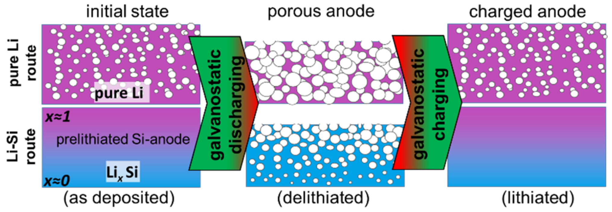
  • Pure Li route: Lithium thin films with a porous morphology are deposited in a special manner by applying an adequate plasma pre-treatment prior to the coating process.
  • Li-Si route: Lithiated Si layers with varying compositions in the growth direction are prepared.
Figure 1. Concept for the synthesis of porous films by PVD of Li (purple) and Li-Si (purple-blue).
Batteries 09 00075 g001

2. Materials and Methods

In order to cover all areas for the preparation and evaluation of high-performance thin-film anodes, multifunctional equipment is required. At least in the development phase of coating technologies, the experimental setup usually must provide more than one coating technology. At the same time, high-throughput and high-quality deposited layers must be ensured. To fulfill the demands for the preparation experiments and subsequent characterization, several Fraunhofer facilities were connected for this work.

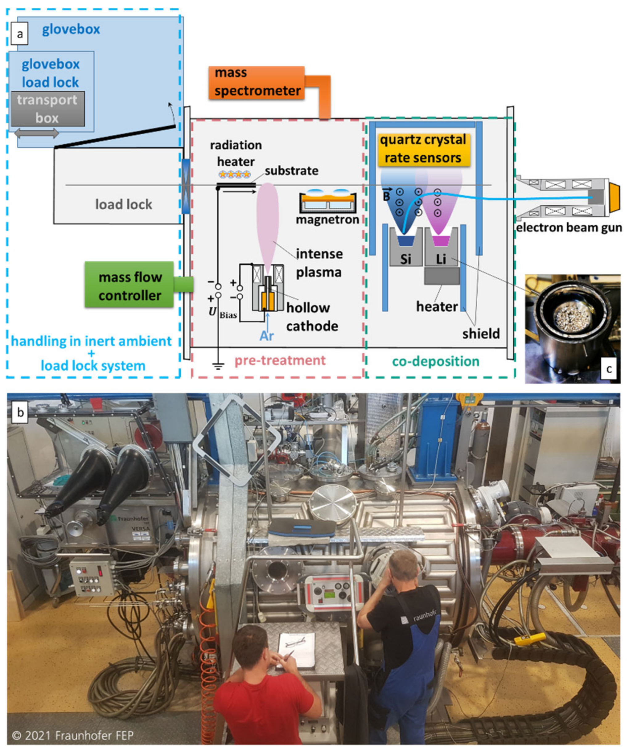
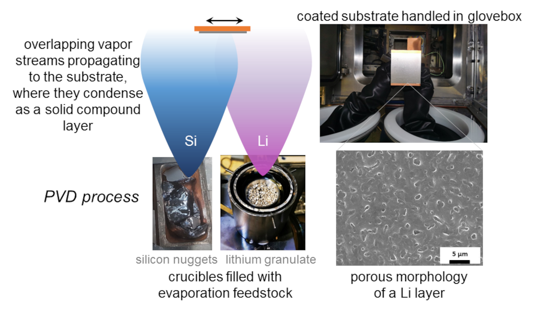
2.1. Coating Preparation

For the coating experiments, the Fraunhofer FEP high vacuum tool VERSA was prepared (Figure 2). The machine can be evacuated either by a turbo pump, by a cryogenic pump system, or by an oil diffusion pump, reaching a base pressure of 2 10 6   mbar . Additionally, process gases such as Ar can be introduced into the vacuum vessel via a mass flow controller to adjust the process pressure p p in the range up to 1 mbar.
Stainless steel and copper sheets as well as copper foil pieces that were 12 µm thick were used as substrates. Stainless steel was chosen, as it is a resilient and cheap model substrate that is easy to handle to ensure the uneventful commissioning of the whole process line. The substrates could be heated up to a defined temperature (20–200 °C) by a rear-side radiation heater. Substrate temperature measurements were realized using rear-side welded thermocouples (type K). By using a steel substrate as a calorimeter probe, the integral heat flux was obtained via the evaluation of the substrate temperature curve T S t [26]. The inward heat flux density q ˙ in can be calculated using the substrate’s specific heat capacity c S , thickness d S , and material density ρ S according to (1).
q ˙ in     =     c S d S ρ S T S t
Within the vacuum chamber, different devices were installed. For substrate pre-treatment, a plasma process was carried out in situ using a hollow cathode arc discharge source generating Ar ions and accelerating them towards the substrate by applying a bias voltage U Bias . The plasma source was placed at a vertical distance to the substrate of 14.5 cm and operated at a chamber pressure of p c = 3 10 4   mbar , at a constant discharge current of 100 A, and at a discharge voltage of 32 V and was enhanced by an annular arranged magnetic field, resulting in a saturation ion current density to substrate of approximately 40 mA/cm2. The deposition of various materials was realized by individual coating stations.
There are some challenges to overcome when using lithium as a material, because lithium strongly reacts with the humidity in the air, or even with nitrogen. Therefore, job safety analysis as well as maintaining sufficient vacuum conditions and an inert transfer of coated substrates and even of Li feedstock material are essential. To realize this, the machine was equipped with an additional self-made glovebox surrounding the load lock’s vacuum chamber (Supplementary Materials Video S1). This allowed the transfer of sensitive materials into a separate external glovebox from SylaTech (Kirkbymoorside, UK) filled with an inert Ar gas atmosphere (O2, H2O < 0.1 ppm) for preparation and also for post-processes (Supplementary Materials Figure S1a). Li granulate was used as an evaporation feedstock (supplier: Fischer Scientific, Loughborough, UK, purity >99.0%, delivered under Ar atmosphere). The granulate was transferred via a container fixed at the substrate transport carrier (Figure S1b) and was released into the evaporation crucible, which was placed at a vertical distance of h Sub = 28.5   cm from the substrate level. The crucible consisted of stainless steel forming a cone-shaped reservoir with a vapor-emitting surface of A c 7   cm 2 and providing a feedstock capacity of 50 cm3 (Figure 2c). The crucible was equipped with a resistive heater controlled to constant temperatures of 500–700 °C to realize lithium evaporation. The static coating process was implemented by placing the substrate over the vapor source for a defined time t . For dynamic deposition, the substrate was moved through the coating zone at a constant velocity v .
The deposition of Li-Si compound layers was realized by the co-evaporation of both materials. Due to the lower saturation vapor pressure of silicon, a more powerful heating method was required for the feedstock material to achieve a significant evaporation rate. Hence for silicon, an electron beam-physical vapor deposition (EB-PVD) process was applied using an axial electron beam gun with a separate vacuum pumping system. Silicon feedstock (5N) was placed in a water-cooled crucible and heated by a dynamically scanning electron beam at a power of 10 kW, leading to melting and evaporation. Both the vapor streams for silicon and lithium were superposed, and consequently, a compound layer was deposited and showed varying concentrations in relation to the relative lateral coating position x S .
Furthermore, a magnetron was installed providently, giving us the opportunity to investigate the suitability of various materials as passivation or encapsulation layers in perspective studies.

2.2. Characterization

The samples were weighed using scales (Mettler XS204, Mettler Toledo GmbH, Gießen, Germany) with an accuracy of 0.1 mg after being placed in a separate Ar glovebox (Figure S1a). Sample transfer was carried out under inert conditions using sealed transport boxes. The mass differences in the substrates Δ m S were measured by weighing the samples before and after each process step, followed by the determination of plasma etching removal r by considering the processed substrate area A S and the mass density ρ S of the substrate material, according to (2).
r = Δ m S A S ρ S
Furthermore, for coating experiments, the distribution of the static deposition rate R x S in relation to the coating position was determined according to (3) by evaluating the layer mass loadings   M x S of substrates arranged side-by-side by considering the layer material mass density ρ , as already introduced previously [10].
R x S = M x S t ρ = 1 t ρ Δ m S x S A S
Moreover, the static deposition rate R Li , 0 vertically above the Li vapor source was measured in situ using a quartz crystal rate sensor that was installed centrally above of the Li-filled crucible. R Li , 0 was calibrated using previously determined reference data of mass loading M obtained by weighing the substrates.
For electrochemical characterization, porous lithium layers were prepared on copper discs of Ø = 14.5 mm. As it will be described in Section 3.3.3 and discussed in Section 4.3, the usage of thin copper foils without applying sufficient substrate cooling is correlated with an intolerable temperature increase. Therefore, for samples prepared for electrochemical characterization, copper discs that were 1–2 mm thick with a higher heat capacity were used in order to avoid substrate temperatures being too high during vapor deposition. Focusing on consistency, 2–5 samples were prepared under comparable conditions. After coating, the samples were transferred to the Fraunhofer IWS under inert conditions using sealed KF vacuum components (Figure S2). Electrochemical tests were carried out in a half-cell configuration in CR2032 coin cells (MTI Corp., Richmond, USA). Within a separate argon-atmosphere glovebox (MBraun glovebox, Garching, Germany, <0.1 ppm O2 and H2O), and the coated samples were assembled using a lithium counter electrode (MTI Corp., Richmond, VA, USA, 99.0%, diameter: 16.5 mm). Both electrodes were separated by a stack of polyethylene/glass fiber separators. Next, 100 µL of LP30, a mixture of 1M LiPF6 in EC:DMC (1:1, v:v), was used. All the cells were electrochemically tested with a BaSyTec, Asselfingen, Germany, Cell Test System at 24 ± 2 °C. For the stripping tests, the cells were galvanostatically discharged at a current density of 0.5 mA/cm2 until reaching the cell voltage of 1.5 V.
Reference samples were transferred to the Fraunhofer IWS under equivalent inert conditions and were inserted into a JEOL JSM-6610LV, Freising, Germany scanning electron microscope (SEM) under an Ar atmosphere. The surface topography was imaged using the secondary electron signal.

3. Results

The preparation of the coatings was realized via subsequent vacuum processes, including transferring the substrate and the feedstock material into the vacuum, in situ cleaning of the coating side, tempering the substrate, depositing the thin film, and unloading the coated substrate under inert conditions.

3.1. Substrate Pre-Treatment

Generally, to ensure high-quality thin films, an appropriate pre-treatment procedure is essential prior to vacuum deposition. In this study, a plasma process was carried out in situ utilizing a hollow cathode arc discharge source to generate argon ions that were accelerated towards the substrate by a bias voltage U Bias . The cleaning effect is based on sputtering off the top layers of atoms [27]. Figure 3 shows the static material removal r vs. the process time t for the substrate materials used: copper and stainless steel, at a constant bias voltage of U Bias = 200   V .
The substrates were placed centrally above of the hollow cathode plasma source for the defined process time. The lines in Figure 3 represent linear data fits, indicating a higher removal rate for copper due to a higher sputter yield. For the determination of the dynamic removal rates, corresponding additional experiments were carried out with and without applying a bias voltage U Bias , and by applying a constant substrate movement velocity v (Table 1). As a result, a dynamic plasma pre-treatment process with optimized default parameters of v = 4.3   mm / s and U Bias = 200   V was applied before subsequent deposition, leading to a material removal of approximately 35 nm for stainless steel and of approximately 140 nm for copper. During this standard plasma pre-treatment process, the substrate temperature T S of sheets that were 1 mm in thickness increased by approx. 115 K for both of the substrate materials used in these experiments.

3.2. Deposition of Pure Lithium Layers

In-vacuum evaporation is a wide-spread and important PVD method for the production of thin films. For this process, the feedstock material is heated to temperatures high enough to evaporate it at a significant rate. Depending on the material saturation vapor pressure curve, suitable heating methods are required. Lithium evaporates at moderated temperatures of 500 °C and above. Hence, resistive heating of the crucible is appropriate. Sufficient vacuum conditions are essential to allow vapor particles to propagate directly to the substrate, where they condense as a solid layer. Several parameters influence the process, such as the crucible temperature T c , the chamber pressure p c , the vertical distance h Sub between the vapor source and substrate, and the relative lateral position x S in relation to the vapor source.

3.2.1. Lithium Deposition Characteristics

For a given distance, the maximum static deposition rate R Li , 0 is achieved vertically above the lithium vapor source. It was measured in situ by a quartz crystal rate sensor positioned vertically along the axis with the crucible. As expected, a disproportional dependency of the deposition rate on the crucible’s evaporation temperature T c was observed experimentally, as indicated by the red symbols in Figure 4. Within the investigated temperature range, a maximum static deposition rate of 120 nm/s and a corresponding dynamic deposition rate of 1 µm·m/min was achieved. The information for the dynamic deposition rate (right ordinate in Figure 4) was estimated by integrating the fit of the lateral-rate distribution over the coating zone (cf. Section 3.3.1.) and was confirmed experimentally by additional dynamic coating trials. Nevertheless, in the temperature range of T c = 600 650   ° C , a sectional linear fit can be approximated (dashed blue line), which is beneficial for controlling the deposition rate via the crucible temperature. However, in general, the agreeing black solid curve in Figure 4 represents a theoretical calculation for the geometric conditions of the coating facility by considering that n originated from the exponent in the characteristic of vapor flux density as well as distance to the substrate h Sub , as in (4):
R 0 = n + 1 m ˙ ρ h Sub 2 2 π .  
Equation (4) shows a linear correlation between the static deposition rate R 0 and evaporation rate m ˙ of the feedstock material [28,29]. Moreover, m ˙ is proportional to the respective coefficients for evaporation α v and for vapor transmission τ to the vapor-emitting area A c of the lithium pool as well as the evaporant’s saturated vapor pressure p s ~   exp 1 / T c , and it contains the molecular weight of the evaporant M D , the universal gas constant R , and the crucible temperature T c . It can be determined by the Knudsen–Langmuir relation in (5) [29,30]:
m ˙ = α v τ A c p s T c   M D 2 π R T c   .
Due to the low molecular weight of lithium, scattering effects with residual gas atoms become dominant, even at relatively low process pressures, affecting the static deposition rate. The red symbols in Figure 5 represent the measured static deposition rate R Li , 0 at changing process pressures p p by varying the Ar gas flow rate into the recipient. The detected values of R Li , 0 drop down to approximately 50%, even for a slightly increased process pressure ranging from 3 10 5   mbar to 9 10 5   mbar . In particular, this is relevant for controlling the deposition rate when there are process irregularities, as they may occur in sophisticated operation conditions, such as co-evaporation.

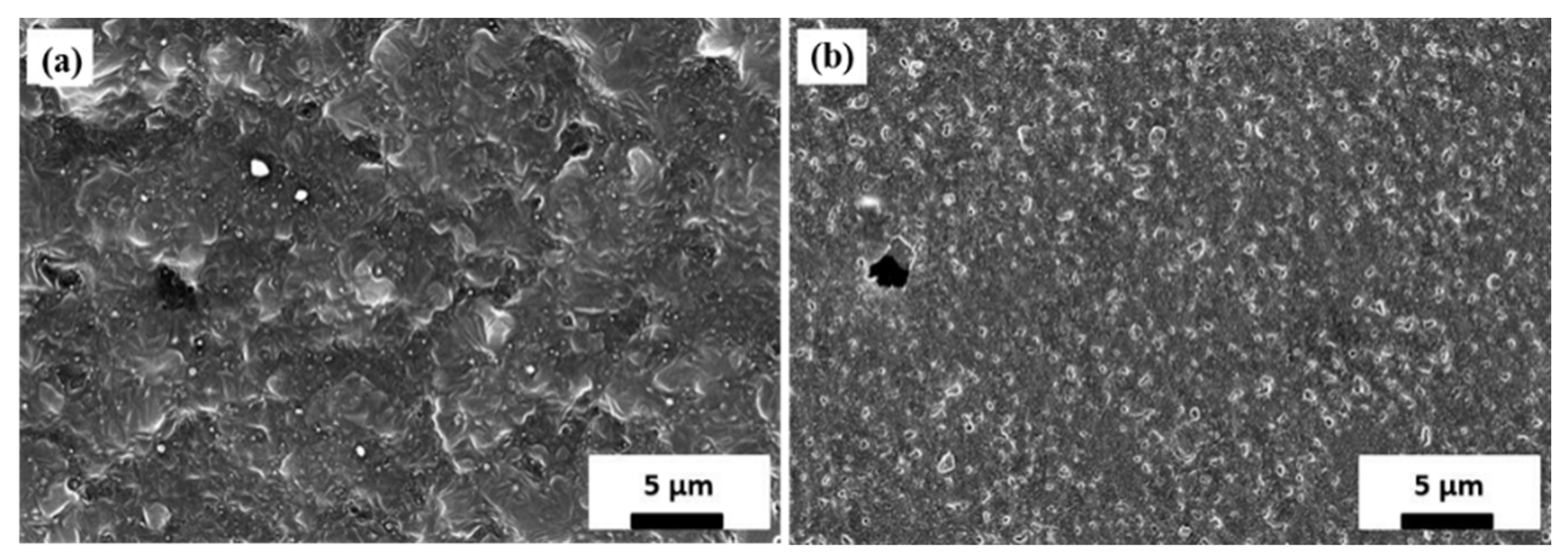
3.2.2. Lithium Layer Morphology

The deposited lithium layers prepared on copper substrates that were 2 mm in thickness were analyzed by SEM. As Figure 6 reveals, a porous layer morphology was achieved by applying a plasma pre-treatment prior to deposition. At a moderate substrate temperature during coating of nearly T S 50   ° C , a median pore diameter of 0.95 µm becomes apparent (Figure 6a), whereas at a higher substrate temperature of T S 150   ° C , an increased median pore diameter of 1.25 µm is achieved (Figure 6b). This reveals that pore size can be manipulated by adapting the substrate temperature. The key feature for preparing a porous structure originates in the plasma pre-treatment process, as shown in Figure 6. Contrary to that, the samples for the micrographs in Figure 7 were prepared under comparable temperature conditions, but without applying a plasma pre-treatment prior to coating. These samples show an almost compact morphology, which is changed slightly by raising the substrate temperature from ≈50 °C (Figure 7a) to ≈150 °C (Figure 7b).

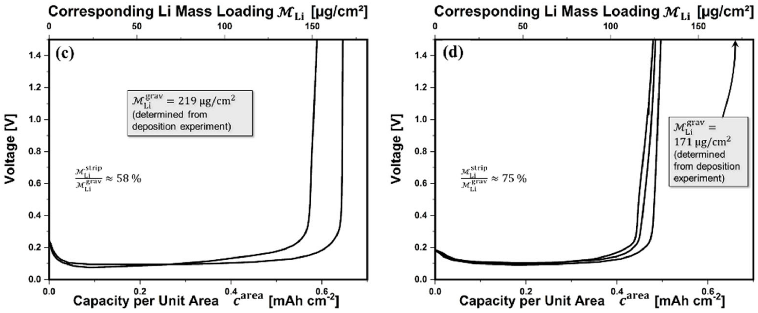
3.2.3. Electrochemical Properties of Pure Lithium Layers

The electrochemical performance of lithium layers synthesized on copper discs of about 1–2 mm in thickness was investigated. Lithium mass loadings in the range of 150 µg/cm2–219 µg/cm2 and with equivalent layer thicknesses of 2.8 µm–4.1 µm, respectively, were deposited. The samples were assembled to coin cells and were discharged at a constant current within stripping experiments. The capacity per unit area c area was calculated from the extracted absolute charge amount by integrating the extracted current density over time. According to the lower abscissa within the diagrams of Figure 8, the voltage vs. capacity c area measurements of several equivalent samples with a porous and an almost compact lithium layer are shown. After consuming all of the available lithium, the voltage increased, and the provided capacity could be determined. The upper abscissa represents the corresponding lithium mass loadings M Li . According to (6), the M Li strip associated with stripping experiments was calculated from the theoretical specific gravimetric capacity of lithium c Li grav = 3861   mAh / g determined according to Faraday’s laws of electrolysis:
M Li strip = c area / c Li grav   .
From the deposition experiments, the gravimetric mass loadings M Li grav were measured separately via weight determination using Relation (3). The corresponding values for M Li grav are annotated within the diagrams of Figure 8. Furthermore, the ratio of both values M Li strip / M Li grav is given in the diagrams of Figure 8. For the porous layers in Figure 8b in particular, the ratio indicates that up to 85% of the Li coating is electrochemically active within the first cycle, i.e., this material is available in batteries for chemical reactions to store energy.

3.3. Deposition of Li-Si Compound Layers

Depositing alloys consisting of lithium and silicon reveals some challenges due to the different material properties. Due to the immense differences in the saturation vapor pressure for these elements ranging over several orders of magnitude, evaporation from multiple separate vapor sources is suitable. In turn, by passing the substrate along the vapor source configuration successively, graded layers can be produced in a simple manner.

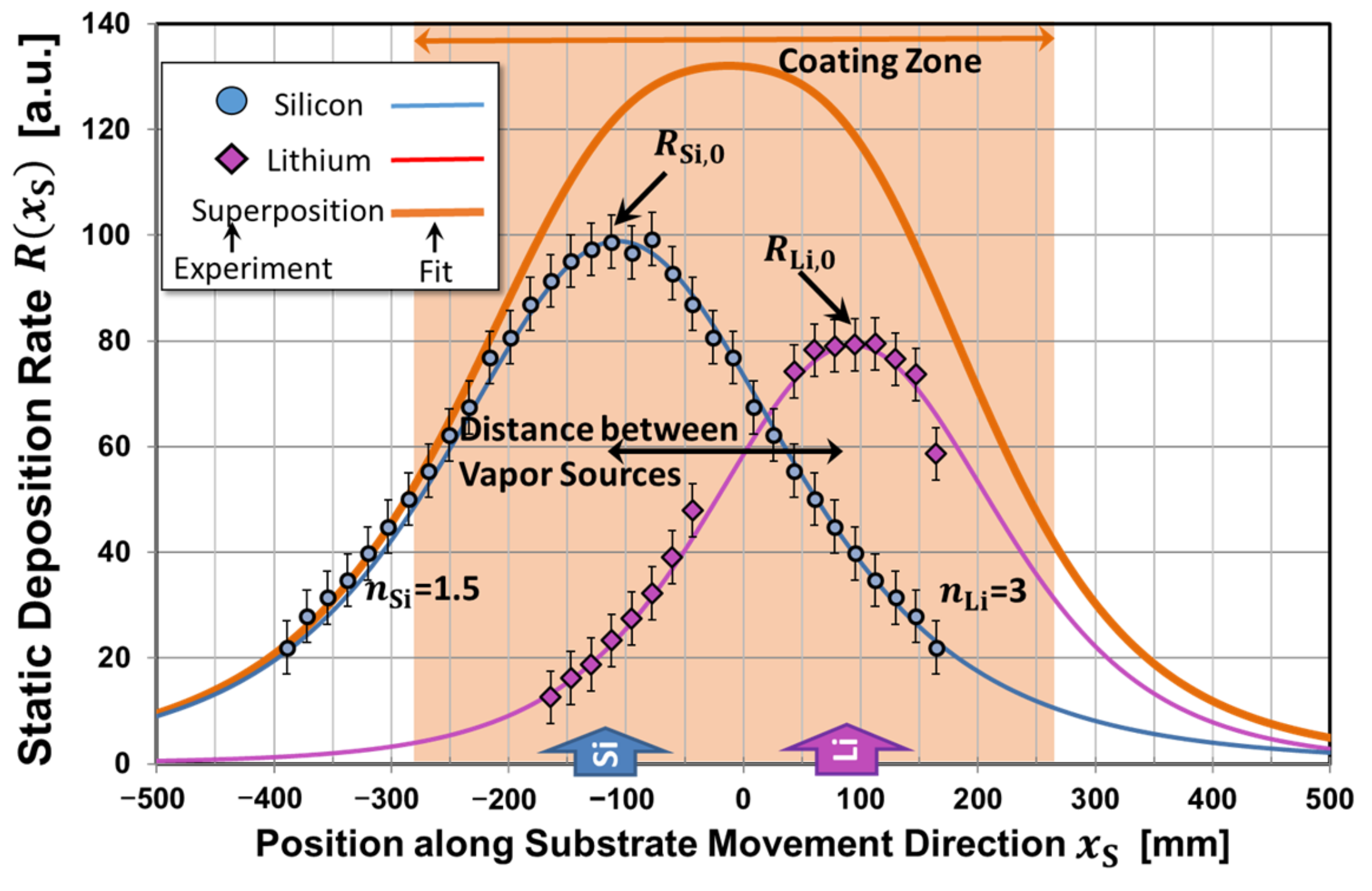
3.3.1. Li-Si Deposition Characteristics

As mentioned before, the static deposition rate depends on the relative substrate position x S . This fact is of importance for the co-evaporation of different materials from several vapor sources. In further experiments, the distributions of static deposition rates R x S were evaluated individually. Experimental data obtained for evaporating Li and Si are displayed in Figure 9.
The lateral distribution can be described according to the well-understood mechanisms of vapor propagation [29] (pp. 173–185), and data approximation can be achieved by curve fitting (thin curves in Figure 9). The vapor flux density of each source depends on the angle ϑ between the vapor propagation direction and the normal of the vapor-emitting surface and is proportional to a cos n ϑ term. Thus, the deposition rate R x S   from one vapor source differs for the lateral position x S of substrates in a side-by-side arrangement, according to (7) and according to generalized Relation (8) [29] (p. 177).
R x S = R 0 cos n + 3 ϑ x S
R x S = R 0 1 1 + x S x 0 h Sub 2 n + 3 2
In addition, coating experiments were conducted during the simultaneous evaporation of Li and Si on 2 mm thick copper sheets at deposition rates of R Li , 0 = 80   nm / s and R Si , 0 = 100   nm / s . The relatively high coating rates were chosen intentionally because at these conditions, a reduction of the parasitic heat ratio α (ref. to Section 3.3.3) is expected [31]. Unfortunately, extensive delamination of the compound layer was observed (Figure S3). Attempts were made to overcome the challenges of layer adhesion by further methodical variation of coating parameters, such as substrate material, the substrate temperature, the deposition rate, the total layer thickness, and the layer composition and the pretreatment procedure. Parameter ranges were evaluated in which tendencies for sufficient layer adhesion became apparent (Figure S3a). However, it turned out that this challenge represents a higher-level development task, which could not be solved sufficiently within the available experimental period. Therefore, a deeper characterization of the Li-Si compound layer was not possible.

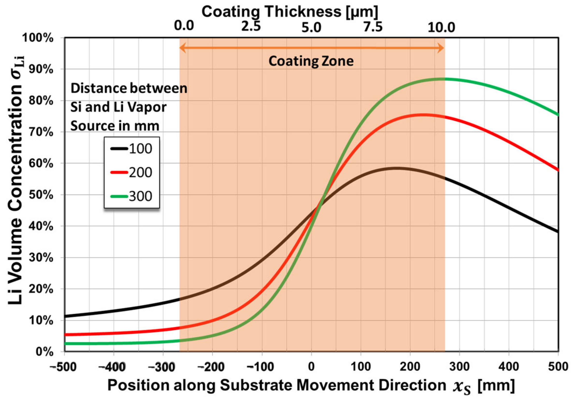
3.3.2. Li-Si Composition

During the co-deposition process, the vapor stream is mixed in the coating region, and a compound material condenses on the substrate. Consequently, the lateral distribution of the total coating rate on a flat substrate results in the distribution having a superposition for single components with shifted vapor source positions x 0 , as illustrated by the thick orange curve in Figure 9. Based on the particular fit of the rate distribution in Figure 9, for a co-deposition, the resulting Li volume concentration σ Li can be estimated as:
σ Li x S = R Li   x S / R Li   x S + R Si   x S .
Figure 10 shows the estimated layer composition, i.e., the volume concentration σ Li vs. the coating position during a static deposition process for three different distances of the vapor sources. For a corresponding dynamic deposition of an exemplary layer that is 10 µm in thickness, the substrate moves at a constant velocity of v 3   mm / s within the coating zone. Consequently, the substrate will be moved through regions with different vapor compositions, and a layer with a concentration gradient will be formed, which is depicted by the upper abscissa in Figure 10. Due to insufficient layer adhesion, this concentration profile could not be evidenced by layer analytics.

3.3.3. Heat Load to Substrate

For the deposition of a layer with a desired film thickness, it is essential to consider substrate heating. In particular, for thin copper foils, a larger temperature rise has to be taken into account due to lower heat capacity at reduced substrate thicknesses. In order to avoid substrate damage or insufficient layer properties, the substrate temperature has to be restricted below critical values. Hence, the resulting heat flux density to the substrate q ˙ in was investigated according to Equation (1) in Section 2.1. For evaluation, a reference deposition rate of R 0 = 120   nm / s was considered. The evaluated values are listed in Table 2, together with the comparison values obtained for the estimated heat flux density of the deposition q ˙ depo and parasitic heat ratio α = q ˙ in / q ˙ depo . The value of q ˙ depo was calculated according to (10) from the materials’ specific enthalpy of fusion h fus [32,33], specific enthalpy of condensation h cond [33,34], mass density ρ , and static deposition rate R 0 .
q ˙ depo     =     h fus + h cond ρ R 0
Compared to Si, the heat flux density of Li seems to be small. Nevertheless, to minimize substrate heating in the samples prepared for characterization (ref. to Section 3.2.2 and Section 3.2.3), copper discs that were 1–2 mm in thickness with a higher heat capacity were used. By using substrates of this thickness, the temperature increase due to the process heat was limited to 4 K and 2 K, respectively. Contrary to that, depositing a 3 µm lithium coating on a copper foil that was 12 µm thick resulted partially in a droplet-shaped layer morphology that looked similar to dew, which could even be seen by the naked eye (Figure S4). This reveals that without adequate cooling equipment, the temperature of the Cu foil exceeds the lithium melting point of 180 °C very easily.

4. Discussion

4.1. Substrate Pre-Treatment

It is well known that water vapor and hydrocarbon vapors are the dominant residual gas species in vacuum systems. Without any conditioning, exposed surfaces such as the substrate-coating side will become contaminated, even after hours of pumping [35] (p. 152). This contamination can influence layer properties, such as composition or adhesion, significantly. In the case of lithium especially, due to its high reactivity, a chemical transformation of the coating material is expected at the interface. The most common in situ cleaning procedure used in PVD processing is plasma cleaning. Therefore, prior to deposition experiments, an intense Ar plasma process was applied, in which Ar ions were accelerated to the substrate, resulting in the material removal of several tens of nm. This should ensure that the substrate surface has consistent properties and should ensure an almost completely clean interface. Such a high removal rate will not be necessary for a perspective fabrication process, and optimization will be necessary regardless.
Nevertheless, by applying this pre-treatment process, surface modifications have to be taken into account. This includes increasing the surface roughness as well as the surface activation by means of plasma exposure. However, as observed in this study, plasma pre-treatment also influences the growth of the lithium layer significantly, leading to a porous morphology. To the best of the authors’ knowledge, a comparable effect has not been reported as of yet. One explanation for the formation of the porous structure is the different thermal expansion behavior between the Cu substrate and the Li layer. For instance, at room temperature, the coefficient of linear thermal expansion differs by a factor of 2.8 (Cu: 16.5 × 10 6   K 1 [36], Li: 46 × 10 6   K 1 [37]). Therefore, considerable shrinking of the Li coating is expected when cooling down from the deposition temperature, which may result in a plastic deformation in the soft lithium as well as in pore formation. Conceivably, without substrate pre-treatment, an interface layer, such as lithium hydroxide, may be built, which acts as promoter for stress relaxation.
Further investigations of the influence of the pre-treatment procedure (e.g., substrate material, the formation of defects on the substrate surface, reachable interface purity, layer adhesion, the resulting layer stress, and attributes for porous layer growth) have not been performed in detail as of yet, and will be the subject of further research work within prospective studies.
Despite of the minimization of parasitic heat load effects, e.g., thermal radiation, by reducing α , and even via the application of a pre-treatment process, layer adhesion became a major challenge for depositing Li-Si compound layers. This was unexpected because in general, sufficient layer adhesion is attributed to the positive effects of plasma pre-treatment. In an earlier study, very thick pure Si layers that were up to 180 µm in thickness could be deposited without layer delamination occurring, and this was due to plasma pre-treatment in particular [38]. One explanation for insufficient layer adhesion is also the different thermal expansion behavior of Li-Si coatings, which may depend on the composition concentration. However, chemical reactions with the substrate may also occur. This has to be addressed in upcoming studies by investigations in a more systematic manner.

4.2. Lithium Coating Process

With the prepared experimental setup, the deposition process of pure lithium was established by thermal evaporation in an almost reproducible manner, and the static deposition rate varied in the range of a few nm/s up to 120 nm/s. As the exponential approximation curve in Figure 4 indicates, very low but also tremendously high deposition rates up to several hundred nm/s seem to be feasible by adapting the crucible temperature. However, for this extended parameter range, particular aspects have to be taken into account.
If the crucible temperature is below 550 °C, the observed coating rate is too low for the deposition of metallic lithium layers in the thickness range of several µm. However, low crucible temperatures are suitable to deposit thin lithium coatings as seed layers [39] or for adding small amounts of lithium to electrodes to compensate for Li consumption during the first formation cycle [40].
If the crucible temperature is above about 800 °C, small temperature differences of about 1 K cause very significant changes in the evaporation rate. Moreover, in this temperature range, external influences due to small changes in process conditions such as thermal radiation may result in drastically inconstant heat dissipation from the vapor source. Consequently, the precise control of the crucible temperature is associated with great technical effort. In particular, in this study, a crucible temperature in the range of about 600–650 °C was preferred because it resulted in the technical advantage of the evaporation rate being able to be approximated by a linear function, and consequently, it could be regulated very precisely via the crucible temperature by a conventional proportional–integral–derivative controller.
However, for overheated crucibles, there is a higher risk of the formation of splashes out of the melt pool, resulting in layer defects. Furthermore, at temperatures near the melting point of the used crucible material, chemical reactions with the side wall may occur. This may result in a higher wear and tear as well as a higher tendency for contamination input. Within the experimental period with over 60 heat-up ramps, the stainless steel crucible showed sufficient performance, with minor decomposition at the side walls, which is consistent with the literature review by Jeppson et al. [33]. On the other hand, some equipment suppliers recommend the use of refractory metals such as tantalum [41]. In additional lithium evaporation experiments, boron nitride and alumina were tested as alternative materials. However, the materials showed total decomposition of the crucible, including the spilling out of the melted lithium, even during the first heat-up trial (Figure S5). This is not unexpected according to literature review by Jeppson et al. [33], but it disagrees with other recommendations for boron nitride from evaporator system suppliers, as per work by the Kurt J. Lesker Company [41], as well as with reported observations for alumina by Vanleeuw et al. [42]. However, for long-term experiments, optimization of the geometric design and material would be necessary. Additionally, in general, for the long-term deposition processes, the feeding of the evaporants has to be taken into account. For lithium, the adaption of existing technical solutions via siphon [43] is suitable, and for silicon, the feeding of Si nuggets into the melting pool is conceivable.
Nevertheless, it has to be mentioned that a relatively large vertical distance h Sub between the vapor source and substrate was implemented within the coating chamber to facilitate the co-deposition experiments. This deprives the achievable deposition rate because, according to Relation (4), the R scales with ~ 1 / h Sub 2 . In a processing tool for coating lithium exclusively, a much smaller distance would be favored.
In Figure 5, the reduction of the Li deposition rate as the process pressure increased was revealed for the central position located vertically above the Li vapor source. Due to scattering effects with the residual gases, it was expected that the rate distribution would change, and that larger variance will be gained. Furthermore, for ideal evaporation, the assumption of α v = τ 1 in (5) is only valid at a low process pressure. Therefore, a reduction of the total evaporation rate m ˙ Li is expected for lithium at higher process pressures. These effects have to be studied in detail in further experiments by introducing different kinds of working gases. Regardless, the results obtained up until now reveal the advantages of thermal evaporation in obtaining an achievable deposition rate in comparison to magnetron sputtering where, in general, higher process pressures become apparent.
Figure 9 reveals variation in the deposition rate over the coating position, leading to an inhomogeneous layer thickness distribution. It is well known that thickness deviations can be homogenized by applying a dynamic deposition process in combination with superposing vapor streams from multiple sources arranged along the motion direction of the substrate [31].

4.3. Substrate Temperature Regime

The substrate temperature became a parameter that affected the manipulation of the layer morphology and presumably layer adhesion. Due to an inward heat flux density q ˙ in , a temperature rise T S / t was observed within the experiments. This effect was particularly pronounced for thin substrates such as metal foils. With regard to Relation (1), the temperature rise can be reduced by increasing the substrate thickness d S . For the coating experiments within the current study, this fact was exploited to avoid temperatures that were too high during vapor deposition without the implantation of additional substrate cooling. By using copper substrates in the thickness range of 1–2 mm, a temperature increase below 4 K was complied. This resulted in the possibility of easily investigating the dependency of layer formation on the substrate temperature. For the application case, thin copper foils have to be processed, for which substrate cooling becomes a challenge despite the low heat flux density during Li. To approach this issue, equipment for the effective cooling of metal strips is necessary, as already demonstrated by Heinß et al. [44]. This is of increased importance for co-deposition with Si, for which an additional heat load has to be considered. Compared to lithium, silicon’s parasitic heat ratio α is amplified by a factor of 3.7 (cf. to Table 2). For EB-PVD processes, the heat load imparted on the substrate is mainly caused by backscattered electrons [29]. Their effect can be reduced by trapping them with a magnetic field above the crucible and by keeping the current of backscattered electrons down by applying a lower EB power. The former can be achieved using hot ceramic crucibles or even through the use of a crucible-free configuration. This is consistent for Si when comparing the results of a former study applying a crucible-free EB-PVD process and reaching a lower parasitic heat ratio of α 3.5 at a reference deposition rate of R Si , 0 = 120   nm / s [31].

4.4. Electrochemical Performance

The stripping experiments in Figure 8 only show small deviations between the measurement curves of each sample set. Furthermore, in Figure 8b, the dashed lines corresponding to the samples prepared using the copper discs that were 1 mm in thickness also show minor differences compared to the other curves within the accuracy of measurements. This indicates that the substrate thickness and the consequently small deviations in the substrate temperature to below 4 K have no major influence on the electrochemical properties. Contrary to that, the capacity values of the different sets of samples differ even more. This is mainly caused by the different lithium thicknesses and the corresponding different lithium mass loadings realized during the different deposition experiments. The corresponding ratios M Li strip / M Li grav show almost comparable values between 58% and 85%. It is supposed that the deposition parameter affect marginally the proportion, which is electrochemically active. Rather, different conditions during sample storage and transport may also have affected the dissimilarities. This has to be investigated and optimized by further experimental work.
In this study, the prepared lithium layers revealed an areal capacity of 0.4–0.6 mAh/cm2. For perspective applications as an anode material, a higher capacity of up to 4 mAh/cm2 would be attractive. This could be achieved by increasing the lithium layer thickness to 20 µm and above. For this, evaluations of electrochemical performance under a relatively thick deposition depth and evaluations of the electrochemical reversibility should be the subject of further investigations.
In the introduction section, it was mentioned that a porous morphology is beneficial during changes to avoid the formation of Li dendrites and to relax the mechanical stress in the Si matrix while the intermetallic phase (LixSi) is being built. Due to insufficient layer adhesion, this has not been proven via adequate galvanostatic charging and discharging in cycling tests that have been conducted up until now. This has to be investigated in detail in prospective research work in combination with the postmortem characterization of the morphology. However, Uxa et al., already provided the general proof of concept by demonstrating the stability of Li0.4Si films for up to 100 cycles [11]. In addition, in this study, a more techno-economical preparation method was demonstrated, enabling sufficient throughput for a perspective production process in principle.
Nevertheless, the results of the electrochemical tests of pure lithium layers are very encouraging on account of the high proportion of electrochemically active material. A further increase above 90% could be feasible by further optimizing the processing steps. This improvement includes various processes for substrate cleaning and pre-treatment, the coating technology itself, the conditions during sample transfer, and refinement processes through post-treatments such as encapsulation. The reduction of so-called “dead lithium” is an essential key to increasing efficiency in batteries, and this aspect is a current subject of intensive international research [45].

4.5. General Consideration of Vacuum Processing and Upscaling Potential

So far, vacuum processes have hardly been used in battery technology. However, a number of general advantages of this methodology have already been pointed out by D. Mattox, e.g., the ability to deposit high-purity films [35] (ch. 5.10). Early critical consideration is essential to evaluate whether the vapor deposition of Li or Si has sufficient potential for industrial-scale application in Li-ion battery production. Therefore, some specifics of the PVD processes will be discussed in this section. A crucial parameter for the productivity of a roll-to-roll coating system is the deposition rate. It is well known that, depending on the evaporation material, very high deposition rates of several micrometers per second can be achieved by PVD [25]. Based on the experience obtained in the present study, static deposition rates of 1–1.5 µm/s or correspondingly high dynamic deposition rates of 20–30 µm·m/min seem to be feasible for Li and Si. This also includes compound layers, which can be produced by mixing vapor streams of Si and Li.
The deposition of vapor is generally accompanied by the transfer of heat to the substrate. A significant and unavoidable portion is contributed by the condensation enthalpy, which is 385 kJ/mol for silicon and 136 kJ/mol for lithium. The heat flux density is to the order of 1–25 W/cm2 at the above-mentioned deposition rates. The cooling of thin battery foils is therefore absolutely necessary to avoid excessively high temperatures during vapor deposition. This was already considered in the early 2000s by Affinito et al., via model predictions for the PVD of lithium on temperature-sensitive substrates such as PET [46,47]. The authors showed that at the production-relevant dynamic deposition rate of 4 μm·m/min and the corresponding heat flux density of 0.92 W/cm2, the web temperature could be limited to below 100 °C by using a cooling drum and by realizing a heat transfer coefficient of 100 W/m2K. As shown by Heinß et al., heat transfer values that are up to 10 times higher are feasible, even for metal strips in a vacuum [44]. After solving the challenges mentioned above, from today’s point of view, a prospective productivity can be estimated hypothetically. With the stated conditions for the coating rate and strip cooling and by assuming a layer thickness of 10 µm, an annual production capacity to the order of 1 million m2 would be quite realistic for an industrial strip evaporation plant.

5. Conclusions

An experimental setup was prepared for handling materials under inert conditions for depositing Li-Si compound layers with a static rate up to 120 nm/s via thermal evaporation for Li and EB-PVD technology for Si. The lithium evaporation process was studied in detail regarding the deposition rate characteristics, heat loads, and the effects of the substrate pre-treatment. Metallic Li thin films and Li-Si compound layers were prepared by applying an innovative approach via vacuum processing with the capability of upscaling to high-throughput production. The feasibility of obtaining porous Li layers with high electrochemical activity was demonstrated. The results are greatly encouraging but also offer space for optimization, especially for the LixSi system regarding the improvement of layer adhesion. Further investigations concerning pore size distribution and its influence on electrochemical performance are necessary in order to further appraise cycle stability. Fraunhofer FEP is open for any cooperation to transfer the results into high-performance products.

6. Patents

For the possibility of manipulating the microstructures of lithium thin films through the application of an adequate substrate pre-treatment, a patent application has been submitted to the German Patent and Trademark Office by the inventors S. Saager, L. Decker and M. Tenbusch with the title “Verfahren zur Herstellung einer porösen Lithiumschicht” under file number DE 10 2022 104 935.3 on 2 March 2022.

Supplementary Materials

The following supporting information can be downloaded at https://www.mdpi.com/article/10.3390/batteries9020075/s1: Video S1. Process steps and their working principles; Figure S1. Experimental setup for pre- and post-processing of Li materials in inert Ar atmosphere; Figure S2. Lithium coating with equivalent layer thickness of 2.8 µm deposited on copper discs that were 2 mm in thickness. To take the photo, the sample was placed on the sealing ring of the KF vacuum transport container; Figure S3. Different types of substrates coated by Li-Si compound layer with various Li contents; Figure S4. Attached copper foil that was 12 µm in thickness prior (a) and after (b) deposition of a Li coating that was 3 µm thick; Figure S5. Ceramic crucibles tested for lithium evaporation.

Author Contributions

Conceptualization, S.S.; methodology, S.S. and L.D.; validation, S.S., L.D., T.K., B.S. and B.Z.; formal analysis, S.S. and L.D.; investigation, S.S. and L.D.; resources, T.K.; data curation, S.S. and L.D.; writing—original draft preparation, S.S.; writing—review and editing, L.D., T.K., B.S. and B.Z.; visualization, S.S.; supervision, S.S. and T.K.; project administration, T.K.; funding acquisition, S.S. All authors have read and agreed to the published version of the manuscript.

Funding

Essential results were obtained in the public project “nextBatt“, funded by the BMBF/German Federal Ministry of Education and Research (funding reference L1FHG42421). Term: 1 February 2021–31 December 2021.

Data Availability Statement

Not applicable.

Acknowledgments

The authors thank Matthias Tenbusch for his technical assistance in addition to his commitment as well as Jens-Peter Heinß for the critical review of the manuscript. We also acknowledge Florian Hoffmann from Fraunhofer IWS for the electrochemical characterization of the lithium layers and Leonid Gerdt from Fraunhofer IWS for the SEM measurements.

Conflicts of Interest

The authors declare no conflict of interest.

Abbreviations and Symbols

Abbreviations
EB-PVDElectron beam-physical vapor deposition
FEPFraunhofer Institute for Organic Electronics, Electron Beam and Plasma
Technology FEP
IWSFraunhofer Institute for Material and Beam Technology IWS
PETPolyethylene terephthalate
PVDPhysical vapor deposition
SEMScanning electron microscope
Symbols
A c Vapor-emitting surface at evaporation crucible
A S Processed substrate area
α Parasitic heat ratio
α v Evaporation coefficient (ideal: α v 1 )
c area Electrochemical capacity per unit area of the electrode
c Li grav Theoretical specific gravimetric capacity of lithium
c S Substrate’s specific heat capacity
d S Substrate thickness
h cond Specific enthalpy of condensation
h fus Specific enthalpy of fusion
h Sub Vertical distance between vapor source and substrate
ϑ Angle of vapor propagation
M D Molecular weight of the evaporant
M , M Li ,   Mass loading
M Li grav Mass loading determined by weight difference
M Li strip Mass loading determined by stripping experiments
m ˙ Evaporation rate
m S Substrate mass
n Exponent in the characteristic of vapor flux density
p c Pressure within the vacuum vessel
p s T c Saturated vapor pressure at a temperature T c
q ˙ depo Heat flux density of deposition
q ˙ in Heat flux density to the substrate
R Universal gas constant
R Si , 0 , R Li , 0 , R 0 Deposition rate vertically above vapor source
R x S Distribution of deposition rate in lateral direction
r Thickness of material removal after pre-treatment
ρ Mass density
ρ S Substrate material density
σ Li Li volume concentration in layer
T c Absolute temperature of the evaporant
T S Substrate temperature
t Process time
τ Vapor transmission coefficient (ideal: τ 1 )
U Bias Bias voltage applied to plasma source
v Substrate moving velocity during process
x S Relative substrate position along movement direction
x 0 Lateral vapor source positions
ØDiameter of copper disc assembled to coin cells

References

  1. Koerver, R.; Zhang, W.; Biasi, L.d.; Schweidler, S.; Kondrakov, A.O.; Kolling, S.; Brezesinski, T.; Hartmann, P.; Zeier, W.G.; Janek, J. Chemo-mechanical expansion of lithium electrode materials—On the route to mechanically optimized all-solid-state batteries. Energy Environ. Sci. 2018, 11, 2142–2158. [Google Scholar] [CrossRef]
  2. Li, J.; Dozier, A.K.; Li, Y.; Yang, F.; Cheng, Y.-T. Crack Pattern Formation in Thin Film Lithium-Ion Battery Electrodes. J. Electrochem. Soc. 2011, 158, A689. [Google Scholar] [CrossRef]
  3. Sun, L.; Wang, X.; Susantyoko, R.A.; Zhang, Q. Copper–silicon core–shell nanotube arrays for free-standing lithium ion battery anodes. J. Mater. Chem. A 2014, 2, 15294. [Google Scholar] [CrossRef]
  4. Si, Q.; Hanai, K.; Imanishi, N.; Kubo, M.; Hirano, A.; Takeda, Y.; Yamamoto, O. Highly reversible carbon–nano-silicon composite anodes for lithium rechargeable batteries. J. Power Sources 2009, 189, 761–765. [Google Scholar] [CrossRef]
  5. Choi, J.W.; Aurbach, D. Promise and reality of post-lithium-ion batteries with high energy densities. Nat. Rev. Mater. 2016, 1, 16013. [Google Scholar] [CrossRef] [Green Version]
  6. Chan, C.K.; Peng, H.; Liu, G.; McIlwrath, K.; Zhang, X.F.; Huggins, R.A.; Cui, Y. High-performance lithium battery anodes using silicon nanowires. Nat. Nanotechnol. 2008, 3, 31–35. [Google Scholar] [CrossRef]
  7. Kim, Y.-L.; Sun, Y.-K.; Lee, S.-M. Enhanced electrochemical performance of silicon-based anode material by using current collector with modified surface morphology. Electrochim. Acta 2008, 53, 4500–4504. [Google Scholar] [CrossRef]
  8. Quiroga-González, E.; Carstensen, J.; Föll, H. Good cycling performance of high-density arrays of Si microwires as anodes for Li ion batteries. Electrochim. Acta 2013, 101, 93–98. [Google Scholar] [CrossRef]
  9. Saager, S.; Scheffel, B.; Zywitzki, O.; Modes, T.; Piwko, M.; Doerfler, S.; Althues, H.; Metzner, C. Porous silicon thin films as anodes for lithium ion batteries deposited by co-evaporation of silicon and zinc. Surf. Coat. Technol. 2019, 358, 586–593. [Google Scholar] [CrossRef]
  10. Saager, S.; Scheffel, B.; Modes, T.; Zywitzki, O. Synthesis of porous silicon, nickel and carbon layers by vapor phase dealloying. Surf. Coat. Technol. 2021, 427, 127812. [Google Scholar] [CrossRef]
  11. Uxa, D.; Hüger, E.; Dörrer, L.; Schmidt, H. Lithium-Silicon Compounds as Electrode Material for Lithium-Ion Batteries. J. Electrochem. Soc. 2020, 167, 130522. [Google Scholar] [CrossRef]
  12. Strauß, F.; Hüger, E.; Heitjans, P.; Trouillet, V.; Bruns, M.; Schmidt, H. Li–Si thin films for battery applications produced by ion-beam co-sputtering. RSC Adv. 2014, 5, 7192–7195. [Google Scholar] [CrossRef] [Green Version]
  13. Liu, Y. Overview of the Recent Progress of Suppressing the Dendritic Growth on Lithium Metal Anode for Rechargeable Batteries. J. Phys. Conf. Ser. 2022, 2152, 12060. [Google Scholar] [CrossRef]
  14. Ren, Y.; Ma, J. Metal Electrodes for Battery Technologies; IOP Publishing: Bristol, UK, 2021. [Google Scholar]
  15. Seong, I.W.; Hong, C.H.; Kim, B.K.; Yoon, W.Y. The effects of current density and amount of discharge on dendrite formation in the lithium powder anode electrode. J. Power Sources 2008, 178, 769–773. [Google Scholar] [CrossRef]
  16. Kühnle, H.; Knobbe, E.; Figgemeier, E. In Situ Optical and Electrochemical Investigations of Lithium Depositions as a Function of Current Densities. J. Electrochem. Soc. 2022, 169, 40528. [Google Scholar] [CrossRef]
  17. Zhang, R.; Li, N.-W.; Cheng, X.-B.; Yin, Y.-X.; Zhang, Q.; Guo, Y.-G. Advanced Micro/Nanostructures for Lithium Metal Anodes. Adv. Sci. 2017, 4, 1600445. [Google Scholar] [CrossRef]
  18. Cai, Y.; Qin, B.; Lin, J.; Li, C.; Si, X.; Cao, J.; Qi, J. Self-Assembly Lightweight Honeycomb-Like Prussian Blue Analogue on Cu Foam for Lithium Metal Anode. ACS Appl. Mater. Interfaces 2021, 13, 23803–23810. [Google Scholar] [CrossRef]
  19. Eom, J.-Y.; Choi, S.H.; Kang, J.-H.; Eom, G.H.; Moon, J.; Park, M.-S. Rational Design of a 3D Li-Metal Electrode for High-Energy Lithium Batteries. ACS Appl. Energy Mater. 2021, 4, 1936–1941. [Google Scholar] [CrossRef]
  20. Yang, T.; Sun, Y.; Qian, T.; Liu, J.; Liu, X.; Rosei, F.; Yan, C. Lithium dendrite inhibition via 3D porous lithium metal anode accompanied by inherent SEI layer. Energy Storage Mater. 2020, 26, 385–390. [Google Scholar] [CrossRef]
  21. Ho, A.S.; Westover, A.S.; Browning, K.; Maslyn, J.A.; Parkinson, D.Y.; Sahore, R.; Dudney, N.; Balsara, N.P. Comparing the Purity of Rolled versus Evaporated Lithium Metal Films Using X-ray Microtomography. ACS Energy Lett. 2022, 7, 1120–1124. [Google Scholar] [CrossRef]
  22. Schönherr, K.; Schumm, B.; Hippauf, F.; Lissy, R.; Althues, H.; Leyens, C.; Kaskel, S. Liquid lithium metal processing into ultrathin metal anodes for solid state batteries. Chem. Eng. J. Adv. 2022, 9, 100218. [Google Scholar] [CrossRef]
  23. Swisher, R.; Yadin, E.; Pipkevich, G. Progress in Vacuum Deposited Lithium Metal Anode Structures. In Proceedings of the 18th International Seminar & Exhibit on Primary and Secondary Batteries, Ft. Landerdale, FL, USA, 5 March 2001. [Google Scholar]
  24. Swisher, R.; Yadin, E.; Pipkevich, G. Web Coating with Lithium—Technical Solution for Metal Anode Structures in Li Batteries. In Proceedings of the 45th Proceedings of the Annual Technical Conference—Society of Vacuum Coaters, Albuquerque, NM, USA, 23–28 June 2002; pp. 535–538. [Google Scholar]
  25. Schiller, S.; Goedicke, K.; Metzner, C. Plasma-activated high-rate electron-beam evaporation for coating metal strips. Mater. Sci. Eng. A 1993, 163, 149–156. [Google Scholar] [CrossRef]
  26. Kersten, H.; Deutsch, H.; Steffen, H.; Kroesen, G.; Hippler, R. The energy balance at substrate surfaces during plasma processing. Vacuum 2001, 63, 385–431. [Google Scholar] [CrossRef]
  27. Heinß, J.-P.; Klose, L. High-Rate Sputter Etching of Substrates Using Hollow-Cathode Arc Discharge Sources. In Proceedings of the 65th Annual Technical Conference Proceedings—Society of Vacuum Coaters, Los Angeles, CA, USA, 30 April–5 May 2022. [Google Scholar] [CrossRef]
  28. Holland, L. Vacuum Deposition of Thin Films; Chapman and Hall: London, UK, 1963. [Google Scholar]
  29. Schiller, S.; Ullrich, H.; Panzer, S. Electron Beam Technology; Verlag Technik GmbH: Berlin, Germany, 1995. [Google Scholar]
  30. Langmuir, I. The Vapor Pressure of Metallic Tungsten. Phys. Rev. 1913, 2, 329. [Google Scholar] [CrossRef]
  31. Saager, S.; Scheffel, B.; Heinß, J.-P. High-rate deposition of high-pure silicon thin films for PV-Absorber layers by crucible-free electron beam physical vapor deposition. Surf. Coat. Technol. 2019, 378, 125019. [Google Scholar] [CrossRef]
  32. Desai, P.D. Thermodynamic Properties of Iron and Silicon. J. Phys. Chem. Ref. Data 1986, 15, 967–983. [Google Scholar] [CrossRef]
  33. Jeppson, D.W.; Ballif, J.L.; Yuan, W.W.; Chou, B.E. Lithium Literature Review: Lithium’s Properties and Interactions; HEDL-TME-78-15; Hanford Engineering Development Lab.: Richland, WA, USA, 1978. Available online: https://www.osti.gov/biblio/6885395-lithium-literature-review-lithium-properties-interactions (accessed on 14 April 2021).
  34. Zulehner, W.; Neuer, B.; Rau, G. Silicon. In Ullmann’s Encyclopedia of Industrial Chemistry; John Wiley & Sons: Hoboken, NJ, USA, 2000. [Google Scholar] [CrossRef]
  35. Mattox, D.M. Handbook of Physical Vapor Deposition (PVD) Processing, 1st ed.; Noyes Publications: Saddle River, NJ, USA, 1998. [Google Scholar]
  36. Nix, F.C.; MacNair, D. The Thermal Expansion of Pure Metals: Copper, Gold, Aluminum, Nickel, and Iron. Phys. Rev. 1941, 60, 597–605. [Google Scholar] [CrossRef]
  37. Winter, M.; University of Sheffield and WebElements Ltd. WebElements Periodic Table Lithium Physical Properties. Available online: https://web.archive.org/web/20220721070335/https://www.webelements.com/lithium/physics.html (accessed on 21 July 2022).
  38. Heinß, J.-P.; Pfefferling, B.; Saager, S.; Temmler, D. High Purity Deposition of Silicon Layers with Rates ≥300 nm/s. In Proceedings of the 31st European Photovoltaic Solar Energy Conference and Exhibition, Hamburg, Germany, 14–18 September 2015; pp. 1022–1025. [Google Scholar] [CrossRef]
  39. Huang, Z.; Zhou, G.; Lv, W.; Deng, Y.; Zhang, Y.; Zhang, C.; Kang, F.; Yang, Q.-H. Seeding lithium seeds towards uniform lithium deposition for stable lithium metal anodes. Nano Energy 2019, 61, 47–53. [Google Scholar] [CrossRef]
  40. Adhitama, E.; Dias Brandao, F.; Dienwiebel, I.; Bela, M.M.; Javed, A.; Haneke, L.; Stan, M.C.; Winter, M.; Gomez-Martin, A.; Placke, T. Pre-Lithiation of Silicon Anodes by Thermal Evaporation of Lithium for Boosting the Energy Density of Lithium Ion Cells. Adv. Funct. Mater. 2022, 32, 2201455. [Google Scholar] [CrossRef]
  41. Kurt, J.; Lesker Company. Lithium Li Evaporation Process Notes. Available online: https://web.archive.org/web/20220721064742/https://www.lesker.com/newweb/deposition_materials/deposition-materials-notes.cfm?pgid=li1 (accessed on 21 July 2022).
  42. Vanleeuw, D.; Sapundjiev, D.; Sibbens, G.; Oberstedt, S.; Salvador Castiñeira, P. Physical vapour deposition of metallic lithium. J. Radioanal. Nucl. Chem. 2014, 299, 1113–1120. [Google Scholar] [CrossRef]
  43. Jahnke, A.; Boger, R.; Götze, T. Method for Refilling an Evaporation Chamber. Google Patents EP 2369033A1, 26 March 2010. [Google Scholar]
  44. Heinß, J.-P.; Lang, P.; Ruppelt, P. Temperature control of metal strip during high-rate vacuum coating. Surf. Coat. Technol. 2016, 290, 39–42. [Google Scholar] [CrossRef]
  45. Chen, K.-H.; Wood, K.N.; Kazyak, E.; LePage, W.S.; Davis, A.L.; Sanchez, A.J.; Dasgupta, N.P. Dead lithium: Mass transport effects on voltage, capacity, and failure of lithium metal anodes. J. Mater. Chem. A 2017, 5, 11671–11681. [Google Scholar] [CrossRef]
  46. Affinito, J.D.; McCann, M.J.; Sheehan, C. Thermal Evaporation of Li: Experiment and a Novel Thermodynamic Model. In Proceedings of the 14th International Conference on Vacuum Web Coating; 2000; pp. 77–94. Available online: https://www.researchgate.net/publication/313139367_Thermal_evaporation_of_Li_experiment_and_a_novel_thermodynamic_model (accessed on 21 July 2022).
  47. Affinito, J.; McCann, M.; Sheehan, C.; Bullock, S. Web Substrate Heating and a Thermodynamic Calculation Method for Li Film Thickness in a Thermal Evaporation System. In Proceedings of the 44th Annual Technical Conference Proceedings—Society of Vacuum Coaters, Philadelphia, PA, USA, 21–26 April 2001; pp. 492–497. [Google Scholar]
Figure 2. Schematic of the experimental setup used for PVD of lithium and silicon (a); picture of the prepared high-vacuum tool, VERSA (b); crucible filled with lithium granulate as evaporation feedstock (c).
Batteries 09 00075 g002
Figure 3. Static material removal r vs. process time t for the used substrate materials copper and stainless steel.
Batteries 09 00075 g003
Figure 4. Measured static deposition rate of Li (left ordinate) and corresponding determined dynamic deposition rate (right ordinate) at a process pressure of 3 10 5   mbar . The black solid curve represents data determined from the saturation vapor pressure of lithium and the geometric conditions of the coating facility according to (4) and (5). In the temperature range of T c = 600 650   ° C , a sectional linear fit can be approximated by the blue dashed curve.
Batteries 09 00075 g004
Figure 5. Li’s static deposition rate at varying process pressures. The dashed line represents the expected trend.
Batteries 09 00075 g005
Figure 6. SEM micrographs of as-deposited pure Li layer surfaces fabricated by applying a plasma pre-treatment prior to coating. The pore size grows by increasing the substrate temperature from ≈50 °C (a) to ≈150 °C (b).
Batteries 09 00075 g006
Figure 7. SEM micrographs of as-deposited pure Li layer surfaces fabricated under comparable conditions, as for the samples in Figure 6, but without applying a plasma pre-treatment prior to coating. The almost compact morphology changes slightly by increasing the substrate temperature from ≈50 °C (a) to ≈150 °C (b).
Batteries 09 00075 g007
Figure 8. Capacity vs. voltage measurements of several equivalent samples with a porous Li layer (a,b) (corresponding to Figure 6a,b) and with an almost compact Li layer (c,d) (corresponding to Figure 7a,b). Data from dashed lines and solid lines correspond to samples prepared using Cu substrates that were 1 mm and 2 mm in thickness, respectively. The M Li axis was calculated from the lithium theoretical specific capacity. This leads to the conclusion that up to 85% of the Li is electrochemically active.
Batteries 09 00075 g008aBatteries 09 00075 g008b
Figure 9. Measured lateral distribution of static deposition rate for silicon and lithium together with fits and their superposition.
Batteries 09 00075 g009
Figure 10. Calculated Li content in terms of substrate position for three distances of vapor sources during static deposition (cf. to fits of Figure 9). For a dynamic deposition of a layer 10 µm in thickness within the coating zone, the curves correspond to the depth vs. concentration profiles in the layer-growth direction (upper abscissa).
Batteries 09 00075 g010
Table 1. Determined dynamic removal rates for the substrate materials stainless steel and copper in relation to bias voltage.
Substrate MaterialWithout Bias U Bias = 200   V
Stainless steel 0.05   nm m / s 0.15   nm m / s
Copper 0.13   nm m / s 0.58   nm m / s
Table 2. Heat flux density to the substrate q ˙ in , expected heat flux density of deposition q ˙ depo , and parasitic heat ratio α = q ˙ in / q ˙ depo at a reference deposition rate of R 0 = 120   nm / s .
Coating Material q ˙ in q ˙ depo α
lithium 0.18   W / cm 2 0.13   W / cm 2 1.38
silicon 2.2   W / cm 2 0.43   W / cm 2 5.12
Disclaimer/Publisher’s Note: The statements, opinions and data contained in all publications are solely those of the individual author(s) and contributor(s) and not of MDPI and/or the editor(s). MDPI and/or the editor(s) disclaim responsibility for any injury to people or property resulting from any ideas, methods, instructions or products referred to in the content.

