Gravure Printing for Lithium-Ion Batteries Manufacturing: A Review


ENEA, Italian National Agency for New Technologies, Energy and Sustainable Economic Development, 80055 Portici, Italy
*
Authors to whom correspondence should be addressed.
Batteries 2023, 9(11), 535; https://doi.org/10.3390/batteries9110535
Submission received: 3 August 2023
/
Revised: 5 September 2023
/
Accepted: 16 October 2023
/
Published: 27 October 2023
(This article belongs to the Section Battery Processing, Manufacturing and Recycling)
Abstract
:Interest in printed batteries is growing due to their applications in our daily lives, e.g., for portable and wearable electronics, biomedicals, and internet of things (IoT). The main advantages offered by printing technologies are flexibility, customizability, easy production, large area, and high scalability. Among the printing techniques, gravure is the most appealing for the industrial manufacture of functional layers thanks to its characteristics of high quality and high speed. To date, despite its advantages, such technology has been little investigated, especially in the field of energy since it is difficult to obtain functionality and adequate mass loading using diluted inks. In this review, the recent results for printed lithium-ion batteries are reported and discussed. A methodology for controlling the ink formulation and process based on the capillary number was proposed to obtain high printing quality and layer functionality. Specific concerns were found to play a fundamental role for each specific material and its performance when used as a film. Considering all such issues, gravure can provide high performance layers. A multilayer approach enables the desired layer mass loading to be achieved with advantages in terms of bulk homogeneity. Such results can boost the future industrial employment of gravure printing in the field of printed batteries.
1. Introduction
The invention of printing was very important for the spread of information, with economic and social consequences. Since then, the printing industry has had large development from the point of view of products and technology. In recent years, traditional printing techniques used in the graphic arts industry have been extensively explored as a new method for low-cost electronics manufacturing thanks to their additive nature, low thermal budget, atmospheric conditions processing, high throughput, use of flexible substrates, roll-to-roll (R2R) compatibility, and potential industrial scalability [1,2]. Unlike conventional one-dimensional coating techniques, traditional printing allows two-dimensional (2D) pattering at high resolution and reproducibility [3].
More recently, an increasing demand for miniaturized, cost-effective, and reliable batteries for feeding small portable and wearable electronics, biomedical devices, and the emerging internet of things (IoT), together with the development of smart and multifunctional materials, have increased the interest in printing technologies as low-cost and easy-to-scale-up methods for battery manufacturing. The commonly used coating production methods limit the flexibility and customizability of devices, impeding their integration with complex geometry [4]. Moreover, the main drawback of coating techniques is the inhomogeneity of the produced layer, which has consequences on their performance in devices, especially in the case of batteries, such as preferential accumulation, the possibility of dendrite formation, and the consequent short-circuits, or the decrease of the available active material and the short cycle life. The 2D printing technologies are particularly appealing for the manufacture of such layered devices since they allow layers of controlled thickness on different substrates to be obtained. Thanks to their recent advances, 3D printing technologies have also been increasingly investigated for battery manufacturing [4,5].
Printed batteries, having a volume below 10 mm3 and a capacity in the range of 5–10 mAh cm−2, have at least one component that is realized by printing technologies, composed of an anode and a cathode, both deposited on current collectors, which are generally not printed, and a separator containing the electrolyte between the electrodes, able to ensure the ion transport [6,7]. Their main advantages are lightweight, flexibility, customizability, possibility to be produced in a large area and the possibility to be interconnected. Printed batteries can be thinner than 1 mm and lighter than 1 g, mechanically flexible and stretchable, foldable, and/or rollable making them also appropriate for smart dust applications [6,8,9]. The geometry and the architecture of these devices are able to influence their performance, especially improving the ion transport; for this reason, different printed designs have been explored, such as the interdigitate or batteries stack. In general, the printed components are the electrodes or the electrolyte [7].
Printing such components requires complex formulation of specific multicomponent inks, involving materials of different nature and size [7]. In fact, functional ink formulation is one of the main challenges for printing batteries since the inks have to be tailored for each printing technique in order to obtain high-energy-density devices with crack-free mechanical flexibility.
Screen printing is the most used and investigated printing technology thanks to the use of concentrated ink formulation (slurry), which easily allow thick layers to be obtained. The already commercially available printed batteries are mainly non-rechargeable, while the printed batteries suitable for portable electronics are rechargeable lithium-ion types [4,6]. Recently, research has been devoted to rechargeable batteries, especially lithium-ion batteries (LiBs), which cover 75% of the market [4].
Among traditional printing techniques, gravure is considered the most efficient, combining very high printing speed (up to 600 m min−1) with high resolution (features down to linewidths and spacing below 2 μm) and high overlay printing registration accuracy (below 20 μm) [10,11,12]. Moreover, gravure printing allows the process to be scaled up to a level higher than other printing technologies [12]. However, gravure is still a challenging technique for printed batteries, essentially due to the high ink requirements, namely low viscosity, causing relatively thin layer formation and low mass loading, making layer functionality also difficult to obtain [13,14].
In this review, the most recent progress in using gravure for printed battery manufacturing is presented. First, the gravure printing process is introduced, illustrating the underlying physics and the features necessary to obtain high printing quality. Then, a methodology, based on the Capillary number (Ca), able to control the process, and the ink formulation, is presented. Following this, the main experimental results are reported, divided into cathode and anode sections based on the involved active material. Finally, a discussion of the experimental work is provided, including general results that are also useful for the gravure printing of different functional layers. Introducing new routes for addressing the main challenges that, to date, have limited the development of gravure printing in this field, this work may pave the way for gravure printing manufacture of different functional layers and possible industrial scale-up, offering many advantages in terms of sustainability, low costs, versatility, and high quality, which can be finally exploited. Future prospects are also outlined.
2. Gravure Printing Process
2.1. Overview of Gravure Printing
Gravure is an industrial mature printing technology that represents the second most commonly used process in Europe and the Far East and the third in the USA [15,16,17]. At present, it is the highest throughput printing technique, showing the highest resolution for printing consumer packaging, long-run magazines, newspapers, catalogs, wallpapers, and postage stamps [15,16,18]. R2R web-fed presses are usually more effective and widely used than sheet-fed gravure ones, due to the large printing runs [16].
Thanks to its appealing characteristics, gravure was investigated during the last decade as a potential route for high throughput functional thin film deposition in several application fields, such as organic electronics (for preparing OTFTs, OLEDs, OPVs), smart packaging, RFID tags, multi-touch sensors, supercapacitors, and energy harvesting devices [2,10,18,19,20,21,22,23].
The simple basic operating principle of the gravure printing process is illustrated in Figure 1 for a single-printing unit. In its most common roll-based configuration, gravure is characterized by direct fluid (ink) transfer from micro-engraved cells of image-carrying motor-driven roll (gravure cylinder) onto a flexible substrate by the pressure of a counter rubber-covered roll (impression cylinder) [24].
Gravure cylinders are usually made of steel and their surface is plated with copper to hold the desired image/pattern, which is etched or engraved in the form of individual cells separated by cell walls [16]. Such cells are typically engraved onto the surface of the printing cylinder using electronic data files by electromechanical engraving using a diamond stylus or a laser procedure [15,26]. By the first method, pyramidal shaped cells are commonly produced, while laser-engraved cells are of semicircular shape [15]. Aspect ratio (AR), defined as depth per width/diameter of the cell, is a fundamental parameter for the interaction processes between ink, cell, and substrate; the typical optimal range is 0.1 < AR < 0.5 [26]. Gravure cell sizes (width and depth) are typically in the range of 10–100 μm, that are engraved on rolls having a diameter exceeding 200 mm [27,28]. Gravure can vary the ink tones by varying the size of each cell. After the copper is etched or engraved, the cylinder is plated with chrome to obtain durability [16].
As shown in Figure 1, the conventional gravure printing process consists of a sequence of sub-processes as follows. (1) Inking: microcells are filled with ink through the partial immersion of the printing cylinder. (2) Doctoring: a doctor blade removes the excess ink from the non-patterned areas leaving ink only in the cells. (3) Transfer: ink is transferred from the surface of the patterned cylinder to the substrate in the form of individual droplets by physical contact. (4) Spreading: a continuous ink film is formed by single droplet coalescence. (5) Drying: the final arrangement of the printed layer is obtained by removing solvents from the film. Each one of such sub-processes has its own ideal operating regime, that concurs to determine the final quality of the printed layer [29]. Industrially, multiple printing units are arranged in series in a press for obtaining multicolor prints, making gravure a wet-on-dry method. Solvents are usually recovered resulting in a highly sustainable process. Register is the ability to print one color directly on the top of the previous color and is maintained by photo-electric electronic motor control systems in the web direction [30].
2.2. Operating Rules for High Quality Gravure Printing Films
To avoid time consuming trial-and-error testing, it is desirable to have a gravure printing model able to predict the optimal conditions for printing high quality layers [31]. Although the operating gravure printing principle is mechanically simple, theoretical modelling is extremely challenging, since the full flow domain is three-dimensional, time-dependent, including the free surface, and moving the contact lines [32,33]. A further challenge is represented by the different length scales involved in the gravure process, that vary from the microns of the typical features up to the centimeters of the cylinder diameter [34]. Moreover, several factors including capillarity, gravity, inertia, viscoelasticity, and solvent evaporation can strongly affect the gravure printing process, making fluid mechanics very complex, and involving several coupled nonlinear phenomena [27,31,34]. As a consequence, rather than consider the gravure printing process in its full complexity, simplified model problems have been proposed to isolate specific phenomena to understand the fundamental aspects of gravure [27,28,32,34,35,36,37,38]. However, the real complex interplay among all the involved phenomena, parameters and different gravure printing sub-processes suggests a process design guided by general considerations [39]. To this aim, dimensional analysis is a useful approach for simplifying the study of the complex multi-physical system behavior. The forces acting on the ink are gravity, inertia, surface tension, and viscous forces [40]. The following dimensionless number can be used for representing the relative magnitudes of such forces:
where Δρ is the density difference between the two phases, g is the gravitational acceleration, L is a problem characteristic length scale, γ is the ink surface tension, U is a problem characteristic speed and η is the ink viscosity. At a printing speed below 1 m s−1 and at the real scale of the problem (L scales down to the microscale), gravity and inertial forces are negligible compared to surface tension and viscous forces, which are therefore the most important forces at the microscopic level [38,40]. Essentially, surface tension forces are the driving forces for ink flow, while viscous ones impede it. Their balance governs printed pattern morphology and fidelity [41]. Such balance is described by the Capillary number (Ca), giving the strength of viscous over surface tension forces, which represent the relevant dimensionless number for ink flow at a particular printing speed (U) [24,28,29]. Most of gravure printing sub-processes (inking, doctoring, transfer) are controlled by Ca, exhibiting different dependencies on it [29]. Exemplifying, low capillary numbers limit the lubrication residue, but the pattern fidelity can be degraded by the ink drag-out from the cells (due to ink wicking up the doctor blade); high capillary numbers prevent drag-out, but ineffective doctoring can leave ink in the non-engraved areas [24,42,43]. In practice, the optimal compromise is reached by adjusting the ink parameters and the printing speed to achieve a Ca ≈ 1 [41]. However, since the final print quality depends on the efficiency of all sub-processes and on the complex interplay of all involved parameters, especially in the case of viscoelastic inks, deviations could be considered to optimize the printing [23,24,29,43]. However, when the cylinder and substrate parameters are fixed (see Table 1) and a Newtonian ink is used, the main parameters are well described by Ca, so that Ca ≈ 1 can be effectively used as a practical rule to guide the ink formulation and the choice of printing speed. In such conditions, macroscopic defects, such as missing dots, incomplete coverage, and streaks, are generally avoided, achieving high quality print.
Nevertheless, when applied to functional printing, such a fluid-dynamic criterion of graphic print quality is also not sufficient to guarantee a high functional quality, which is influenced by additional specific parameters, as discussed below in the case of printed batteries.
2.3. Ink Formulation for Gravure Printed Batteries
Printing requires materials to be deposited in liquid form (inks) [44]. Inks are typically multicomponent mixtures consisting of functional elements, binders, solvents, and additives. The other components serve to facilitate functional element printability on the substrate: binders provide uniform film-forming and adhesion of the functional particles to each other and to the substrate; solvents uniformly dissolve or disperse all ink components, providing ink requirements for the specific printing systems; additives can be used to adjust some specific properties of the ink [45]. Ink composition determines the ink physical properties such as viscosity, surface tension, wetting characteristics, density, and drying rate that are considered fundamental for obtaining high quality print [46]. Viscosity is the measure of ink internal flow resistance and gives its rheological description with respect to stress, deformation, and time [46]. Newtonian inks exhibit a viscosity constant over a wide range of shear rates and stress for a specific temperature. Conversely, non-Newtonian inks show deviations having a more complex response [45]. Typically, gravure printing inks are highly diluted to obtain a low viscosity in the range of 1–100 mPa s [24], as the inks have to flow in and out of engraved cells at a high speed [15]. Solvents also determine the ink surface tension [45,47] affecting the ink wettability [48], which is a fundamental parameter in a surface-energy-dependent process as gravure printing. In particular, as a rule of thumb, since the ink flows towards the surfaces with higher surface energy, to achieve an adequate wettability (thus favoring inking and transfer sub-processes)
where γi, γc, γs are the ink surface tension, the surface energy of the chromed printing cylinder (42 mN m−1), and the surface energy of the substrate, respectively [49,50]. In industry, it is generally accepted that γi, has to be 10 mN m−1 lower than γs to achieve good ink wetting [46]. A proper wetting is crucial for functional printing, where film continuity and homogeneity are key criteria [51]. Finally, another important parameter is the solvent evaporation rate, which governs the drying process leading to the solid film final morphology and microstructure [24,48]. Such a sub-process is controlled by the solvent boiling temperature and the way it is removed. The combination of such parameters has to guarantee that the critical freezing time τc is larger than the characteristic leveling time τl of the wet printed layer for obtaining complete droplet merging and perfect film leveling on the substrate [52]. For all these reasons, the selection of solvents is crucial for ink formulation.
A functional ink suitable to realize the electrodes has to contain specific components in an appropriate ratio: active material, electrical conductor, and binder. In ink processing, the sequence of adding various components and the mixing method affect the ink homogeneity and rheology. The most used mixing method consists of mixing the active material and the conductive carbon in powder form to obtain a good conductive network; following that, binder solution is added to the mixed powders; finally, solvent addition allows one to achieve the ink requirements suitable for gravure printing. Active materials are usually available in the form of aggregates. A material dispersion process is required to attempt disaggregation into primary particles. Depending on viscosity and desired particle size, different dispersion technologies can be used; ball-milling and agitation are the most common in the case of low viscosity ink [46].
3. Main Results
In this section, the main results of gravure printing as a manufacturing method for lithium-ion batteries are presented [53,54,55,56,57]. Mainly, gravure printing has been investigated for the production of electrodes, thus the results are divided in two sub-sections related to cathodes and anodes.
The first experimental attempts were focused on demonstrating the possibility to employ gravure printing in electrode manufacturing. Once such a possibility was successfully proved, the printing quality was investigated. The experiments were aimed to verify if a good printing quality could guarantee the layer functionality, providing a methodology, based on Ca, able to control the process and ink formulation, where the latter represents one of the main challenges.
From the experimental point of view, electrode printing has some common features. Inks suitable for gravure printing have low viscosity (1–100 mPa s), thus large amounts of solvent are required. To enhance the sustainability of the process, water was selected as the main solvent; consequently, a water-soluble binder as the carboxymethyl cellulose (CMC) was used. The preparation method, involving water-based inks and a low quantity of solid materials (<20 wt%), makes the process safe and sustainable. Water-based ink has a surface tension (72 mN m−1) higher than that of the printing cylinder (42 mN m−1). To enable the printing process, 2-propanol (23 mN m−1) was used as co-solvent lowering the surface tension of the inks. Ball-milling was investigated as an ink mixing technique. All layers were printed using a commercial lab-scale IGT G1-5 gravure printer (IGT, Alemere, The Netherlands) equipped with a cylinder having a line density of 40 lines cm−1, stylus angle of 120°, cell depth of 72 µm, and screen angle of 53°. No final calendaring was performed. A multilayer approach was often adopted to achieve the desired mass loading for practical applications (1.5 mg cm−2), with overlapping of several layers of ink. Between each layer a blowof nitrogen was used for fast drying, while the final layer was treated at 100 °C for one hour to completely remove the solvents. This led to the production of functional composite layers, generating a unicum layer of adequate mass loading able to work as the electrode. The correlation between the layer microstructure and its performance was investigated. The introduction of ball-milling and the optimization of ink preparation allowed improvement of the layer quality in terms of homogeneity and material distribution.
3.1. Gravure Printing Cathodes
3.1.1. LFP-Based Gravure Printed Cathodes
The first attempt to realize a gravure printed cathode was made using lithium iron phosphate (LFP) as active material [53]. The used solvent was a mixture of water and 2-propanol (80/20 wt/wt%). The cathodes were obtained through a multilayer deposition, overlapping inks at decreasing concentration; all other printing parameters (cylinder, speed, pressure, drying temperature) were kept constant to simplify the overall production process. In this way, composite cathodic materials were successfully gravure printed onto aluminum foils. It was noted that the performances of the printed cathodes could be improved by increasing the layer homogeneity.
LFP-based cathodes were also used for investigating the methodology for ink formulation mainly based on the Ca. In this case the inks, that met the gravure requirements (solid content of 15 wt%), were gravure printed on aluminum foil with overlapping of ten layers of the same ink to reach an adequate mass loading for cathodic practical use (see Table 2). Since the rheological behavior of the tested inks was considered Newtonian (see Figure 2), the viscosity values used to calculate the Ca were those obtained at shear rate 100 s−1. To improve ink mixing, a short ball-milling time (3 min) was used. Ball-milled ink showed a viscosity lower than non-ball-milled ink, probably due to the decrease in the large particle size, which improves particle flow and packing. The prepared inks were gravure printed using the parameters reported in Table 2.
The reported images of printed samples obtained by scanning electronic microscopy (SEM) (see Figure 3) showed high quality, absence of visible defects, very good coverage, and high uniformity in the material distribution. The ball-milling provoked a slight decrease in particle size as was evident on the top surface of the printed layers.
Both samples were characterized from the electrochemical point of view as reported in Figure 4. The specific capacity of the printed cathode obtained by ball-milled ink is very close to the theoretical value (170 mAh g−1), while the printed cathode obtained by non-ball-milled ink displayed a slightly lower specific capacity, especially at high rates. Probably, this is due to the short ball-milling time capability of slightly decreasing the active material particle size, increasing its surface/volume ratio, and improving the interconnections among components at a fixed percentage.
3.1.2. LMO-Based Gravure Printed Cathodes
A study on cathodes using lithium manganese oxide (LMO) as the active material was conducted as a further example of how to face the ink formulation challenge. In this case, changing the solvent mixture was necessary to make the ink suitable for gravure printing; in particular, a mixture of water and 2-propanol (90/10 wt/wt%) was used to prevent agglomeration phenomena that increased the ink viscosity and worsened the printing quality.
Inks containing a solid content of 18 wt% fulfilled the gravure requirements and were gravure printed on aluminum foils, with overlapping of seven layers to achieve an adequate mass loading (see Table 3). Also in this case, the inks could be considered Newtonian, while ball-milling did not affect the viscosity (see Figure 5). In Figure 6 the SEM images of gravure printed cathodes prepared with or without ball-milling are reported.
Ball-milling was introduced in the ink preparation to improve mixing using a short treatment time (5 min) to prevent particle size reduction. The ball-milled sample appears slightly denser than the non-ball-milled one, as confirmed by its higher mass loading. All printed samples showed high quality, namely very good coverage and high uniformity in the material distribution. The printed cathodes showed a specific capacity of about 100 mAh g−1 for non-ball-milled ink and 110 mAh g−1 for the ball-milled one. The slightly higher capacity of the cathode with ball-milled ink confirmed an improvement in the material layer distribution, without affecting the specific capacity of the active material, which was not disaggregated due to short ball-milling. However, the specific capacity was lower than the theoretical value (148 mAh g−1). Probably, the specific features have to be taken into account to improve the performance of such a cathodic layer, thus needing further investigation.
3.1.3. CAM-Based Gravure Printing Anodes
The first attempt to gravure print the anodic layer was carried out using a high performance conversion/alloying material (CAM). The CAMs are an emerging class of materials able to combine conversion and alloying mechanisms in one single material to overcome the challenges of these two mechanisms and, thus, benefitting from their advantages. In this case, the carbon coated Zn0.9Fe0.1O was used as active material for the anode fabrication. The used CAM has a high capacity (theoretically 966 mAh g−1) and long cycle life. The high specific capacity of the material could eventually compensate for the low mass loading; nevertheless, the multilayer approach allowed mass loading useful for practical applications to be obtained.
To increase the homogeneity of the layers and to decrease the size of the starting powder aggregates, different mixing methods were tried, such as sonication, ball milling and the combination of both. Sonication showed a very low disaggregation effect, while ball-milled ink yielded a more homogeneous printed layer with much smaller aggregates. The combination of both mixing methods worsened the size homogeneity in the layer, probably due to partial re-aggregation phenomena. In Figure 7 the top surface images of printed samples using different mixing techniques are displayed.
In this case, the best compromise between the highest mass loading of a single layer and the printing quality was obtained for ball-milled ink having 14 wt% of solid content, viscosity of 100 mPa s. and a mixture of water and 2-propanol (80/20 wt/wt%) as solvent. Such ink was printed on corona pretreated Cu foil with the conditions reported in Table 4. To reach an adequate mass loading, a multilayer approach was adopted, with overlapping of up to 15 layers of the same ink. The ink content and the process parameters were fixed to simplify the overall process.
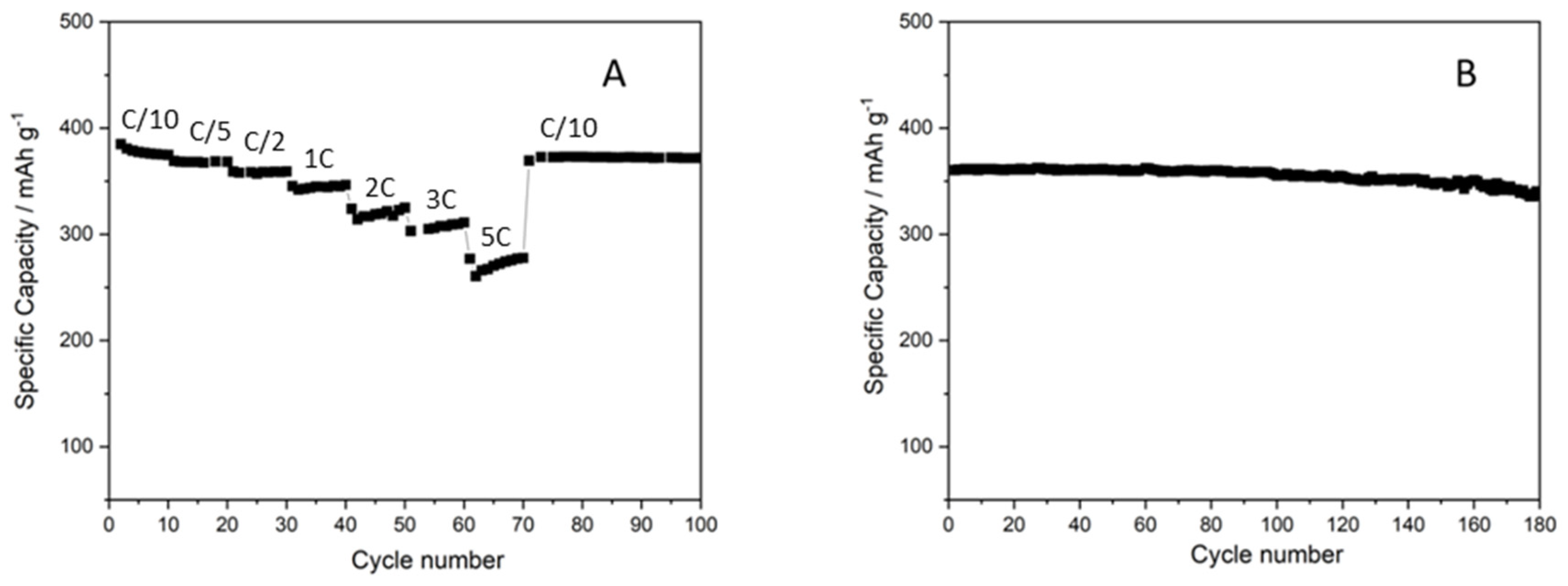
The disaggregation techniques affected the final layer density. The layer obtained by ball-milled ink had double the apparent density compared to that obtained by sonicated ink (0.3 g cm−3 vs. 0.6 g cm−3). All printed samples showed long life cyclability (>100 cycles) and comparable coulombic efficiency; however, the samples printed by ball-milled inks showed higher capacity at high cycling rates. Overlapping of 15 layers provided a mass loading of 1.7 mg cm−2 without affecting the homogeneity of the cathode and its performance, which is closer to that obtained by a five layers cathode. The high homogeneity of gravure printed samples was also proved by cross section SEM images which showed that the particle distribution is homogenous as well as in the bulk. Thanks to such high homogeneity, printed cathodes have a very long cycle life, showing stable capacity up to 400 cycles as reported in Figure 8.
3.1.4. Graphite-Based Gravure Printing Anodes
Gravure printing was also investigated for the mass production of well-known low-cost graphite-based anodes for LiBs, by exploring the influence of process parameters on layer microstructure and performance of the printed anodes. In this case, the best printed anode was obtained using ink having 18 wt% of solid content, ball-milled for three hours, overlapping of six ink layers and using a solvent mixture of water and isopropanol (90/10 wt/wt%) as reported in Table 5.
The low content of 2-propanol was necessary to prevent agglomeration phenomena of carbonaceous material. Three hour ball-milling was used to improve the material distribution inside the layer, decreasing the initial particle size of graphite while the particle morphology changed from spherical to platelet-like (see Figure 9).
The used conditions led to a good particle arrangement in the printed layer, obtaining a capacity close to the theoretical value (372 mAh g−1), high efficiency, good stability, and long life cyclability (see Figure 10), even at high rate and cycling at different rates.
4. Discussion
A comparison of the results obtained by gravure printed electrodes with those produced by different 2D printing techniques, such as screen printing, aerosol, inkjet, laser direct writing, and spray coating is quite difficult since the printed active materials are different in most cases [4]. However, a comparative table of electrodes produced by different printing techniques involving similar materials is reported here (see Table 6). Even when the same active material is used (e.g., LFP or graphite), other components change (binder, solvents, electric conductor), resulting in different electrodic layers [58,59,60,61]. Few cases are comparable from the materials point of view, but the ingredient amount is different, changing the properties of the resulting electrodes and thus their performances [61]. Moreover, the electrochemical characterization is generally carried out in different devices and/or at different rates, making it even more difficult to compare performances.
The reported results show that gravure printing was successfully proved as a high-quality manufacturing method for LiBs. The used materials were selected as a reference, being well-established or of low-cost or high-performance. The reported experimental works were able to respond to the main challenges related to gravure technology as never having been carried out before in the field of printed batteries. In the case of electrode production, the manufacturing process can limit the capacity displayed by an active material, resulting in being lower than theoretical [64]. In fact, in most cases in which a material is used in film form, layer manufacturing is crucial for its functionality and efficiency. Moreover, due to gravure printing the requirement of low viscosity inks and ink formulation is challenging, making it difficult to obtain the proper layer functionality, especially in the case of composite materials like electrodes, and in the mass loading suitable for practical applications. Furthermore, every time a material in the composite changes, a new study of a gravure ink in terms of formulation and preparation process is needed.
Controlling the ink preparation could solve the functionality issue and strongly decrease the process time, promoting the industrial use of gravure printing. In this regard, a methodology based on Ca for ink formulation and the printing process was demonstrated as a good driver to obtain high gravure printing quality, which is a necessary condition for layer functionality. Nevertheless, high graphical quality is not sufficient to guarantee high functional quality, which is influenced by additional specific parameters, as shown by the experimental results, where the contribution of mass loading, component ratio, material size, component distribution, and layer density plays a fundamental role for printed batteries. Specific issues depend on the materials and the role that the printed layer has to exploit as device component. For example, in the case of ink preparation, ball-milling treatment is necessary to disaggregate the starting powders (for graphite and CAMs) while for other materials short ball-milling can be used as the mixing method (LFP and LMO). According to the specific case, the mixing methods can affect the layer density, the particle distribution, and the film homogeneity. However, assuming that the rheological ink behavior is Newtonian, when all the conditions for Ca ~ 1 are respected, a good printing quality can be achieved and the layer functionality obtained. When the ink has a non-Newtonian behavior or has limited pot life, other rules have to be investigated to achieve a good printing quality.
On the other hand, every single time the system, the application, and the involved materials change, a specific study is necessary to achieve high performances, taking into account specific parameters and challenges fundamental in each considered case. When specific material requirements are satisfied, especially in terms of optimal particle size and distribution, very good performances are achieved. In fact, in such cases, a long cycle life is obtained with cycling at high and constant capacity close to the theoretical value, without fading, for a large number of cycles, as a consequence of the high homogeneity and lack of defects in the printed layers. Gravure printing is also able to produce very homogeneous surface characteristics, providing a very fine controlled and spike-less interface with the electrolyte and forming a very uniform SEI (solid electrolyte interface) preventing local accumulation of materials during the charge–discharge process (lithiation–delithiation), thus avoiding dendrite formation.
The low mass loading challenge due to low-viscosity gravure inks has been solved thanks to a multilayer approach. Such a method allows provision of the desired mass loading. Moreover, the multilayer approach, together with high printing quality, represents an advantage over the conventional coating techniques, also providing high homogeneity in the bulk of the final printed layer. In fact, the microstructure of the consolidated dried film depends on several parameters related to the involved particles (size, morphology, electrostatic charge, concentration), the rheology of the ink system, and the drying conditions [65]. Inks (and slurries) are typically non-stabilized dispersions, consisting of heterogeneous particles of very different sizes; as a consequence, aggregation and sedimentation phenomena can occur [66,67]. In particular, sedimentation has to be taken into account because of the particles size and the possibility of forming re-aggregates, which can be in the non-colloidal range [65,68]. Such phenomena can compromise the final functionality of the layer creating inhomogeneity. Moreover, fluid and particles motion occurring during the dying process can also strongly affect the final film microstructure, leading to horizontal and vertical drying profiles, thus resulting in spatial inhomogeneity [65,69,70]. In particular, the balance of diffusion and sedimentation during evaporation determines the vertical distribution. It is assumed that the smaller particles are in the evaporation regime, whereas the larger particles and the aggregates are in the sedimentation-dominant regime. This strongly encourages possible segregation in the drying layer, particularly across the thickness and especially when the dispersion is deposited in a single step producing a large thickness, i.e., tape casting, doctor blade, and other coating techniques typically employed in battery manufacturing. Multilayer gravure printing allows segregation phenomena to be minimized, controlling the particle distribution, especially along the film thickness.
In addition, a multilayer approach enables improvement of the final surface characteristics, smoothing the previous layer by over-position of the subsequent one, thanks to the printed solvent. This generates good electrode–electrolyte interface, demonstrated by the high stability of the performances and the long cycle life of the printed electrodes. As a result, the reproducibility and the quality of the gravure process permit the overlap of high number of layers without affecting the properties, and thus the performances, of the final multilayer.
Finally, it should be highlighted that gravure printed electrodes were not subjected to any post-processing calendaring. This step is generally used to achieve the proper density/interconnection and adhesion with the current collectors when coating techniques are employed for the electrode manufacture. Skipping the calendaring represents a simplification of the overall process, particularly desired for industry.
The obtained results can be useful for extending gravure printing as a manufacturing technique for different functional layers, since a method to obtain good printing quality has been validated, enabling specific layer functionality. All such experimental works can boost the potential use of gravure in the industrial manufacturing of printed batteries, thanks to its high scalability and easy technological transfer.
5. Future Prospective
The main challenge of printed battery future development is represented by the monolithic integration of such devices into electronics or energy harvesting systems, avoiding the use of battery holders or cables, and also tending to all-printed devices [7,71]. To this aim, other related issues have to be faced. Nowadays, the printed elements of batteries are mainly the electrodes and the separator/electrolyte. In the future, printing of current collectors and battery packaging systems will have to be considered. The formulation of suitable inks based on metal powder or carbonaceous materials, having tunable rheological properties and able to provide adequate conductivity, can contribute to the possible printing of current collectors. The printing of packaging and encapsulating materials for printed batteries introduces new issues such as moisture and air barrier, flexibility, and mechanical properties that need to be addressed. One of the hypotheses for the future printed batteries is the introduction of new printing techniques able to respond to new concerns and actual drawbacks. The appealing new printing technologies are the high-fidelity inkjet, the electrodynamic process (EHD), and 3D printing. In addition, 4D printing can represent a new manufacturing method for future printed batteries [72]. Such a new printing technology produces a 3D structure able to change the shape and morphology under external stimulation.
Different printed storage systems are also being considered to supply energy to flexible electronics and IoTs as an alternative to printed batteries, such as printed capacitors and supercapacitors, opening the way to the printing of new materials [7].
Also in the future, the efforts of the investigations will be focused on ink formulation which remains a challenging task [4]. In fact, also considering different printing techniques, the necessity of controlling the stability of the ink dispersions, such as to tune their rheology properly, is fundamental to govern the process and to control the printed layer characteristics/performances and to favor industrial scale up. Changing the binder may imply the use of different solvents; other solvents/co-solvents may be investigated as well as different additives to obtain further process improvements such as higher ink stability and lower dry temperature/time. Furthermore, the ink control could provide the ability to improve the electronic and ionic connection, crucial for the battery process [7]. The use of new and high performance materials can be very helpful in improving the printed layer performances. To enhance the sustainability of the process and the devices, large attention must be paid to the choice of suitable materials, with requirements of being green and cost-effective.
Regarding gravure printing, in the case of Newtonian ink, ink control can be obtained thanks to the proposed methodology based on the Ca, providing an important contribution to the possible industrial implementation of such printing technology for the future manufacturing of printed batteries. Such a methodology is a useful tool for the printing quality, while the specific concerns of each battery component and material have to be considered to achieve good performances. Thanks to the demonstrated results, the study on gravure printed batteries may be extended to systems different from LiBs, such as sodium-ion batteries and all-solid-state batteries, thus even promoting battery safety.
6. Conclusions
In this review, the recent main results on gravure printing manufacturing for printed batteries are reported. In particular, the manufacture of LiB electrodes was presented and discussed, providing general results, helpful for gravure printing of functional layers and addressing some of the main challenges related to the selected printing technology. The formulation of gravure printable inks and the choice of process parameters suitable for high printing quality are ruled by a methodology based on Ca, able to guarantee layer functionality. Nevertheless, specific concerns of each material and battery component have to be considered to achieve high-quality performance gravure printed layers. The multilayer approach was found suitable to obtain the desired layer mass loading also using low-viscosity inks. Such layer-by-layer deposition was found useful in providing high homogeneity also in the layer bulk. The future perspectives of printed batteries were also introduced. The findings shown can boost possible future development and industrial scaling of gravure for printed battery production.
Author Contributions
Conceptualization, M.M. and G.S.; methodology, M.M. and G.S.; validation, M.M. and G.S.; investigation, M.M. and G.S.; data curation, M.M. and G.S.; writing—original draft preparation, M.M. and G.S.; writing—review and editing, M.M. and G.S.; visualization, M.M. and G.S.; supervision, M.M. and G.S.; funding acquisition, M.M. and G.S. All authors have read and agreed to the published version of the manuscript.
Funding
This work was partially supported by Accordo di Programma MiTe-ENEA 2021–2024 Mission Innovation (CUP I62C21000380001) WP2-Materiali sostenibili per accumulo elettrochimico dell’energia and partially supported by Accordo di Programma 2022–2024 Progetto di ricerca integrato: Tecnologie di accumulo elettrochimico e termico (CUP I53C22003080001) WP1- Accumulo elettrochimico: materiali avanzati.
Institutional Review Board Statement
Not applicable.
Data Availability Statement
The raw data can be obtained from the corresponding authors upon reasonable request.
Conflicts of Interest
The authors declare no conflict of interest.
References
- Krebs, F.C. Fabrication and processing of polymer solar cells: A review of printing and coating techniques. Sol. Energy Mater. Sol. Cells 2009, 93, 394–412. [Google Scholar] [CrossRef]
- Roth, B.; Søndergaard, R.R.; Krebs, F.C. Roll-to-roll printing and coating techniques for manufacturing large-area flexible organic electronics. In Handbook of Flexible Organic Electronics, Materials, Manufacturing and Applications, 1st ed.; Logothetidis, S., Ed.; Woodhead Publishing: Cambridge, UK, 2015; pp. 171–197. [Google Scholar]
- Abbel, R.; Galagan, Y.; Groen, P. Roll-to-Roll Fabrication of Solution Processed Electronics. Adv. Eng. Mater. 2018, 20, 1701190. [Google Scholar] [CrossRef]
- Costa, C.M.; Gonçalves, R.; Lanceros-Méndez, S. Recent advances and future challenges in printed batteries. Energy Storage Mater. 2020, 28, 216–234. [Google Scholar] [CrossRef]
- Lyu, Z.; Lim, G.J.H.; Koh, J.J.; Li, Y.; Ma, Y.; Ding, J.; Wang, J.; Hu, Z.; Wang, J.; Chen, W.; et al. Design and Manufacture of 3D-Printed Batteries. Joule 2021, 5, 89–114. [Google Scholar] [CrossRef]
- Oliveira, J.; Costa, C.M.; Lanceros-Méndez, S. Printed Batteries Materials, Technologies and Applications; John Wiley & Sons Ltd.: Chichester, UK, 2018. [Google Scholar]
- Tong, C. Printed Flexible Electrochemical Energy Storage Devices. In Advanced Materials for Printed Flexible Electronics, 1st ed.; Springer Series in Materials Science; Springer: Cham, Switzerland, 2022; Volume 317, pp. 433–521. [Google Scholar]
- Zhu, M.; Shmidt, O.G. Tiny robots and sensors need tiny batteries—Here’s how to do it. Nature 2021, 589, 195. [Google Scholar] [CrossRef] [PubMed]
- You, C.-Y.; Hu, B.-F.; Xu, B.-R.; Zhang, Z.-Y.; Wu, B.-M.; Huang, G.-S.; Song, E.-M.; Mei, Y.-F. Foldable-circuit-enabled miniaturized multifunctional sensor for smart digital dust. Chip 2022, 1, 100034. [Google Scholar] [CrossRef]
- Jung, M.; Kim, J.; Koo, H.; Lee, W.; Subramanian, V.; Cho, G. Roll-to-roll gravure with nanomaterials for printing smart packaging. J. Nanosci. Nanotechnol. 2014, 14, 1303–1317. [Google Scholar] [CrossRef] [PubMed]
- Grau, G.; Kitsomboonloha, R.; Subramanian, V. Fabrication of a high-resolution roll for gravure printing of 2 µm features. In Proceedings of the SPIE Organic Photonics + Electronics, San Diego, CA, USA, 9–13 August 2015. [Google Scholar]
- Tiara, A.M.; Moon, H.; Cho, G.; Lee, J. Fully roll-to-roll gravure printed electronics: Challenges and the way to integrating logic gates. Jpn. J. Appl. Phys. 2022, 61, SE0802. [Google Scholar]
- Hwang, S.S.; Cho, C.G.; Park, K.-S. Stabilizing LiCoO2 electrode with an overlayer of LiNi0.5Mn1.5O4 by using a Gravure printing method. Electrochem. Commun. 2011, 13, 279–283. [Google Scholar] [CrossRef]
- Rassek, P.; Wendler, M.; Krebs, M. Industrial Perspective on Printed Batteries. In Printed Batteries Materials, Technologies and Applications, 1st ed.; Lanceros-Méndez, S., Costa, C.M., Eds.; John Wiley & Sons Ltd.: Chichester, UK, 2018; pp. 185–192. [Google Scholar]
- Szentgyörgyvölgyi, R. Gravure printing. In Printing on Polymers, 1st ed.; Izdebska, J., Thomas, S., Eds.; William Andrew: Waltham, MA, USA, 2016; pp. 199–215. [Google Scholar]
- Romano, F. Printing processes. In Professional Prepress, Printing, and Publishing, 1st ed.; Romano, F., Ed.; Prentice Hall PTR: Hoboken, NJ, USA, 1999; pp. 89–186. [Google Scholar]
- Xia, Z.; Cai, T.; Li, X.; Zhang, Q.; Shuai, J.; Liu, S. Recent Progress of Printing Technologies for High-Efficient Organic Solar Cells. Catalysts 2023, 13, 156. [Google Scholar] [CrossRef]
- Lee, W.; Koo, H.; Sun, J.; Noh, J.; Kwon, K.-S.; Yeom, C.; Choi, Y.; Chen, K.; Javey, A.; Cho, G. A fully roll-to-roll gravure-printed carbon nanotube-based active matrix for multi-touch sensors. Sci. Rep. 2015, 5, 17707. [Google Scholar] [CrossRef] [PubMed]
- Tekoglu, S.; Hernandez-Sosa, G.; Kluge, E.; Lemmer, U.; Mechau, N. Gravure printed flexible small-molecule organic light emitting diodes. Org. Electron. 2013, 14, 3493–3499. [Google Scholar] [CrossRef]
- Zhang, Q.; Huang, L.; Chang, Q.; Shi, W.; Shen, L.; Chen, Q. Gravure-printed interdigital microsupercapacitors on a flexible polyimide substrate using crumpled graphene ink. Nanotechnology 2016, 27, 105401. [Google Scholar] [CrossRef]
- Montanino, M.; De Girolamo Del Mauro, A.; Tesoro, M.; Ricciardi, R.; Diana, R.; Morvillo, P.; Nobile, G.; Imparato, A.; Sico, G.; Minarini, C. Gravure-printed PEDOT:PSS on flexible PEN substrate as ITO-free anode for polymer solar cells. Polym. Compos. 2015, 36, 1104–1109. [Google Scholar] [CrossRef]
- Montanino, M.; Sico, G.; Prontera, C.T.; De Girolamo Del Mauro, A.; Aprano, S.; Maglione, M.G.; Minarini, C. Gravure printed PEDOT:PSS as anode for flexible ITO-free organic light emitting diodes. Express Polym. Lett. 2017, 11, 518–523. [Google Scholar] [CrossRef]
- Sico, G.; Montanino, M.; Loffredo, F.; Borriello, C.; Miscioscia, R. Gravure Printing for PVDF Thin-Film Pyroelectric Device Manufacture. Coatings 2022, 12, 1020. [Google Scholar] [CrossRef]
- Sico, G.; Montanino, M.; Prontera, C.T.; De Girolamo Del Mauro, A.; Minarini, C. Gravure printing for thin film ceramics manufacturing from nanoparticles. Ceram. Int. 2018, 44, 19526–19534. [Google Scholar] [CrossRef]
- Garcia, A.J.L.; Sico, G.; Montanino, M.; Defoor, V.; Pusty, M.; Mescot, X.; Loffredo, F.; Villani, F.; Nenna, G.; Ardila, G. Low-Temperature Growth of ZnO Nanowires from Gravure-Printed ZnO Nanoparticle Seed Layers for Flexible Piezoelectric Devices. Nanomaterials 2021, 11, 1430. [Google Scholar] [CrossRef]
- Hennig, G.; Selbmann, K.-H.; Brockelt, A. Laser engraving in gravure industry. In Proceedings of the SPIE 6157, EPIC/SPIE Workshop on Laser Applications in Europe, Dresden, Germany, 9 December 2005. [Google Scholar]
- Sankaran, A.K.; Rothstein, J.P. Effect of viscoelasticity on liquid transfer during gravure printing. J. Non-Newton. Fluid Mech. 2012, 175, 64–75. [Google Scholar] [CrossRef]
- Lee, J.A.; Rothstein, J.P.; Pasquali, M. Computational study of viscoelastic effects on liquid transfer during gravure printing. J. Non-Newton. Fluid Mech. 2013, 199, 1–11. [Google Scholar] [CrossRef]
- Grau, G.; Cen, J.; Kang, H.; Kitsomboonloha, R.; Scheideler, W.J.; Subramanian, V. Gravure-printed electronics: Recent progress in tooling development, understanding of printing physics, and realization of printed devices. Flex. Print. Electron. 2016, 1, 023002. [Google Scholar] [CrossRef]
- Walsh, J.J. A Review of the Graphic Arts Industry. IEEE Trans. Aerosp. Electron. Syst. 1970, AES-6, 422–431. [Google Scholar] [CrossRef]
- Michels, J.J.; de Winter, S.H.P.M.; Symonds, L.H.G. Process optimization of gravure printed light-emitting polymer layers by a neural network approach. Org. Electron. 2009, 10, 1495–1504. [Google Scholar] [CrossRef]
- Kapur, N. A parametric study of direct gravure coating. Chem. Eng. Sci. 2003, 58, 2875–2882. [Google Scholar] [CrossRef]
- Ahn, S.; Na, Y. On the Ink Transfer Process in Gravure Printing. In Proceedings of the Computational Science and Its Applications—ICCSA 2007 International Conference, Kuala Lumpur, Malaysia, 26–29 August 2007. [Google Scholar]
- Kumar, S. Liquid Transfer in Printing Processes: Liquid Bridges with Moving Contact Lines. Annu. Rev. Fluid Mech. 2015, 47, 67–94. [Google Scholar] [CrossRef]
- Hewson, R.W.; Kapur, N.; Gaskell, P.H. A two-scale model for discrete cell gravure roll coating. Chem. Eng. Sci. 2011, 66, 3666–3674. [Google Scholar] [CrossRef]
- Nguyen, H.A.D.; Shin, K.; Lee, C. Effect of nip force on ink transfer in high resolution roll-to-roll printing. Int. J. Precis. Eng. Manuf. 2015, 16, 517–523. [Google Scholar] [CrossRef]
- Nguyen, H.A.D.; Lee, C.; Shin, K.-H.; Lee, D. An Investigation of the Ink-Transfer Mechanism During the Printing Phase of High-Resolution Roll-to-Roll Gravure Printing. IEEE Trans. Compon. Packag. Manuf. Technol. 2015, 5, 1516–1524. [Google Scholar] [CrossRef]
- Campana, D.M.; Ubal, S.; Giavedoni, M.D.; Saita, F.A.; Carvalho, M.S. Three dimensional flow of liquid transfer between a cavity and a moving roll. Chem. Eng. Sci. 2016, 149, 169–180. [Google Scholar] [CrossRef]
- Wu, J.-T.; Carvalho, M.S.; Kumar, S. Emptying of gravure cavities containing shear-thinning and shear-thickening liquids. J. Non-Newton. Fluid Mech. 2019, 268, 46–55. [Google Scholar] [CrossRef]
- Grau, G. Gravure-Printed Electronics: Devices, Technology Development and Design. Ph.D. Thesis, University of California, Berkeley, CA, USA, 1 May 2017. [Google Scholar]
- Huang, Q.; Zhu, Y. Printing conductive nanomaterials for flexible and stretchable electronics: A review of materials, processes, and applications. Adv. Mater. Technol. 2019, 4, 1800546. [Google Scholar] [CrossRef]
- Grau, G.; Scheideler, W.J.; Subramanian, V. High-resolution gravure printed lines: Proximity effects and design rules. In Proceedings of the SPIE 9569, SPIE Organic Photonics + Electronics, San Diego, CA, USA, 17 September 2015. [Google Scholar]
- Zavanelli, N.; Kim, J.; Yeo, W.H. Recent Advances in High-Throughput Nanomaterial Manufacturing for Hybrid Flexible Bioelectronics. Materials 2021, 14, 2973. [Google Scholar] [CrossRef] [PubMed]
- Khan, S.; Lorenzelli, L.; Dahiya, R.S. Technologies for printing sensors and electronics over large flexible substrates: A review. IEEE Sens. J. 2014, 15, 3164–3185. [Google Scholar] [CrossRef]
- Maddipatla, D.; Narakathu, B.B.; Atashbar, M. Recent Progress in Manufacturing Techniques of Printed and Flexible Sensors: A Review. Biosensors 2020, 10, 199. [Google Scholar] [CrossRef] [PubMed]
- Hu, G.; Kang, J.; Ng, L.W.T.; Zhu, X.; Howe, R.C.T.; Jones, C.G.; Hersam, M.C.; Hasan, T. Functional inks and printing of two-dimensional materials. Chem. Soc. Rev. 2018, 47, 3265–3300. [Google Scholar] [CrossRef] [PubMed]
- Secor, E.B.; Lim, S.; Zhang, H.; Frisbie, C.D.; Francis, L.F.; Hersam, M.C. Gravure Printing of Graphene for Large-area Flexible Electronics. Adv. Mater. 2014, 26, 4533–4538. [Google Scholar] [CrossRef] [PubMed]
- Schlisske, S.; Rosenauer, C.; Rödlmeier, T.; Giringer, K.; Michels, J.J.; Kremer, K.; Lemmer, U.; Morsbach, S.; Daoulas, K.C.; Hernandez-Sosa, G. Ink Formulation for Printed Organic Electronics: Investigating Effects of Aggregation on Structure and Rheology of Functional Inks Based on Conjugated Polymers in Mixed Solvents. Adv. Mater. Technol. 2020, 6, 2000335. [Google Scholar] [CrossRef]
- Glasser, A.; Cloutet, E.; Hadziioannou, G.; Kellay, H. Tuning the rheology of conductiong polymer inks for various deposition processes. Chem. Mater. 2019, 31, 6936–6944. [Google Scholar] [CrossRef]
- Chang, Q.; Cao, C.; Qiao, H.; Hu, Y.; Xiao, G.; Shi, W. Ink transfer for printed flexible microsupercapacitors. Carbon 2021, 178, 285–293. [Google Scholar] [CrossRef]
- Stamm, J.; Daume, D.; Hartwig, T.; Oschmann, M.; Schäfer, J.; Sauer, H.M.; Dörsam, E. Dynamic interferometric imaging of the thickness distribution of evaporating thin liquid films. J. Coat. Technol. Res. 2019, 16, 1663–1671. [Google Scholar] [CrossRef]
- Hernandez-Sosa, G.; Bornemann, N.; Ringle, I.; Agari, M.; Dörsam, E.; Mechau, N.; Lemmer, U. Rheological and drying considerations for uniformly gravure printed layers: Towards large-area flexible organic light-emitting diodes. Adv. Funct. Mater. 2013, 23, 3164–3171. [Google Scholar] [CrossRef]
- Montanino, M.; Sico, G.; De Girolamo Del Mauro, A.; Moreno, M. LFP-Based Gravure Printed Cathodes for Lithium-Ion Printed batteries. Membranes 2019, 9, 71. [Google Scholar] [CrossRef] [PubMed]
- Montanino, M.; Sico, G.; De Girolamo Del Mauro, A.; Asenbauer, J.; Binder, J.R.; Bresser, D.; Passerini, S. Gravure-Printed Conversion/Alloying Anodes for Lithium-Ion Batteries. Energy Technol. 2021, 9, 2100315. [Google Scholar] [CrossRef]
- Montanino, M.; De Girolamo Del Mauro, A.; Paoletti, C.; Sico, G. Gravure Printing of Graphite-Based Anodes for Lithium-Ion Printed Batteries. Membranes 2022, 12, 999. [Google Scholar] [CrossRef] [PubMed]
- Montanino, M.; Paoletti, C.; De Girolamo Del Mauro, A.; Sico, G. The Influence of the Gravure Printing Quality on the Layer Functionality: The Study Case of LFP Cathode for Li-Ion Batteries. Coatings 2023, 13, 1214. [Google Scholar] [CrossRef]
- Montanino, M.; Paoletti, C.; De Girolamo Del Mauro, A.; Sico, G. Gravure printed composites based on Lithium Manganese Oxide: A study case for Li-ion batteries manufacturing. Macromol. Symp. 2023; submitted. [Google Scholar]
- Sousa, R.E.; Oliveira, J.; Gören, A.; Miranda, D.; Silva, M.M.; Hilliou, L.; Costa, C.M.; Lanceros-Mendez, S. High performance screen printable lithium-ion battery cathode ink based on C-LiFePO4. Electrochim. Acta 2016, 196, 92–100. [Google Scholar] [CrossRef]
- Gören, A.; Mendes, J.; Rodrigues, H.M.; Sousa, R.E.; Oliveira, J.; Hilliou, L.; Costa, C.M.; Silva, M.M.; Lanceros-Méndez, S. High performance screen-printed electrodes prepared by a green solvent approach for lithium-ion batteries. J. Power Source 2016, 334, 65–77. [Google Scholar] [CrossRef]
- Deiner, L.J.; Jenkins, T.; Powell, A.; Howell, T.; Rottmayer, M. High capacity rate capable aerosol jet printed Li-ion battery cathode. Adv. Eng. Mater. 2019, 21, 1801281. [Google Scholar] [CrossRef]
- Lee, S.H.; Li, K.; Huang, C.; Evans, J.D.; Grant, P.S. Spray-printed and self-assembled honeycomb electrodes of silicon-decorated carbon nanofibers for Li-ion batteries. ACS Appl. Mater. Interfaces 2019, 11, 603–612. [Google Scholar] [CrossRef]
- Mateo, J.V.; Matthew, K.; Pekarovicova, A.; Fleming, P.D. Inks for Li-ion battery anodes printed by rotogravure. Adv. Print. Media Technol. 2022, 47, 171–176. [Google Scholar]
- Pekarovicova, A.; Matthew, K.; Mateo, J.V.; Al-Ajlouni, K.; Fleming, P.D. Li-ion battery anodes printed by rotogravure. J. Print Media Technol. Res. 2023, 12, 7–14. [Google Scholar]
- Jin, Y.; Yu, H.; Liang, X. Simple approach: Heat treatment to improve the electrochemical performance of commonly used anode electrodes for Lithium-ion batteries. ACS Appl. Mater. Interfaces 2020, 12, 41368–41380. [Google Scholar] [CrossRef] [PubMed]
- Cusola, O.; Kivistö, S.; Vierros, S.; Batys, P.; Ago, M.; Tardy, B.L.; Greca, L.G.; Roncero, M.B.; Sammalkorpi, M.; Rojas, O.J. Particulate coatings via evaporation-induced self-assembly of polydisperse colloidal lignin on solid interface. Langmuir 2018, 34, 5759. [Google Scholar] [CrossRef] [PubMed]
- Vesaratchanon, S.; Nikolov, A.; Wasan, D.T. Sedimentation in nano-colloidal dispersions: Effects of collective interactions and particle charge. Adv. Colloid Interface Sci. 2007, 134–135, 268. [Google Scholar] [CrossRef] [PubMed]
- Aimar, P.; Bacchin, P. Concentrated phases of colloids or nanoparticles: Solid pressure and dynamics of concentration processes. In Nano-Science: Colloidal and Interfacial Aspect; Starov, V.M., Ed.; CRC Press: Boca Raton, FL, USA; Taylor and Francis Group: Oxfordshire, UK, 2010. [Google Scholar]
- Schulz, M.; Keddie, J.L. A critical and quantitative review of the stratification of particles during the drying of colloidal films. Soft Matter 2018, 14, 6181. [Google Scholar] [CrossRef] [PubMed]
- Wang, M.; Brady, J.F. Microstructures and mechanics in the colloidal film drying process. Soft Matter 2017, 13, 8156. [Google Scholar] [CrossRef] [PubMed]
- Trueman, R.E.; Lago Domingues, E.; Emmett, S.N.; Murray, M.W.; Routh, A.F. Auto-stratification in drying colloidal dispersions: A diffusive model. J. Colloid Interface Sci. 2012, 377, 207. [Google Scholar] [CrossRef]
- Choi, K.-H.; Ahn, D.B.; Lee, S.-Y. Current status and challenges in printed batteries: Toward form factor-free monolithic integrated power sources. ACS Energy Lett. 2018, 3, 200–236. [Google Scholar] [CrossRef]
- Jiang, Z.; Chen, G. Research Progress and Prospect of Printed Batteries. In Proceedings of the China Academic Conference on Printing and Packaging CACPP 2022, Jian, China, 11–13 November 2022. [Google Scholar]
Figure 1.
Operating roll-based gravure printing principle, showing inking (1), doctoring (2), transfer (3), spreading (4), and drying (5) sub-processes. Adapted with permission from Ref. [25].
Figure 1.
Operating roll-based gravure printing principle, showing inking (1), doctoring (2), transfer (3), spreading (4), and drying (5) sub-processes. Adapted with permission from Ref. [25].

Figure 2.
Viscosity versus shear rate for non-ball-milled (no BM) and ball-milled (BM) LFP-based inks with permission from Ref. [56].
Figure 2.
Viscosity versus shear rate for non-ball-milled (no BM) and ball-milled (BM) LFP-based inks with permission from Ref. [56].
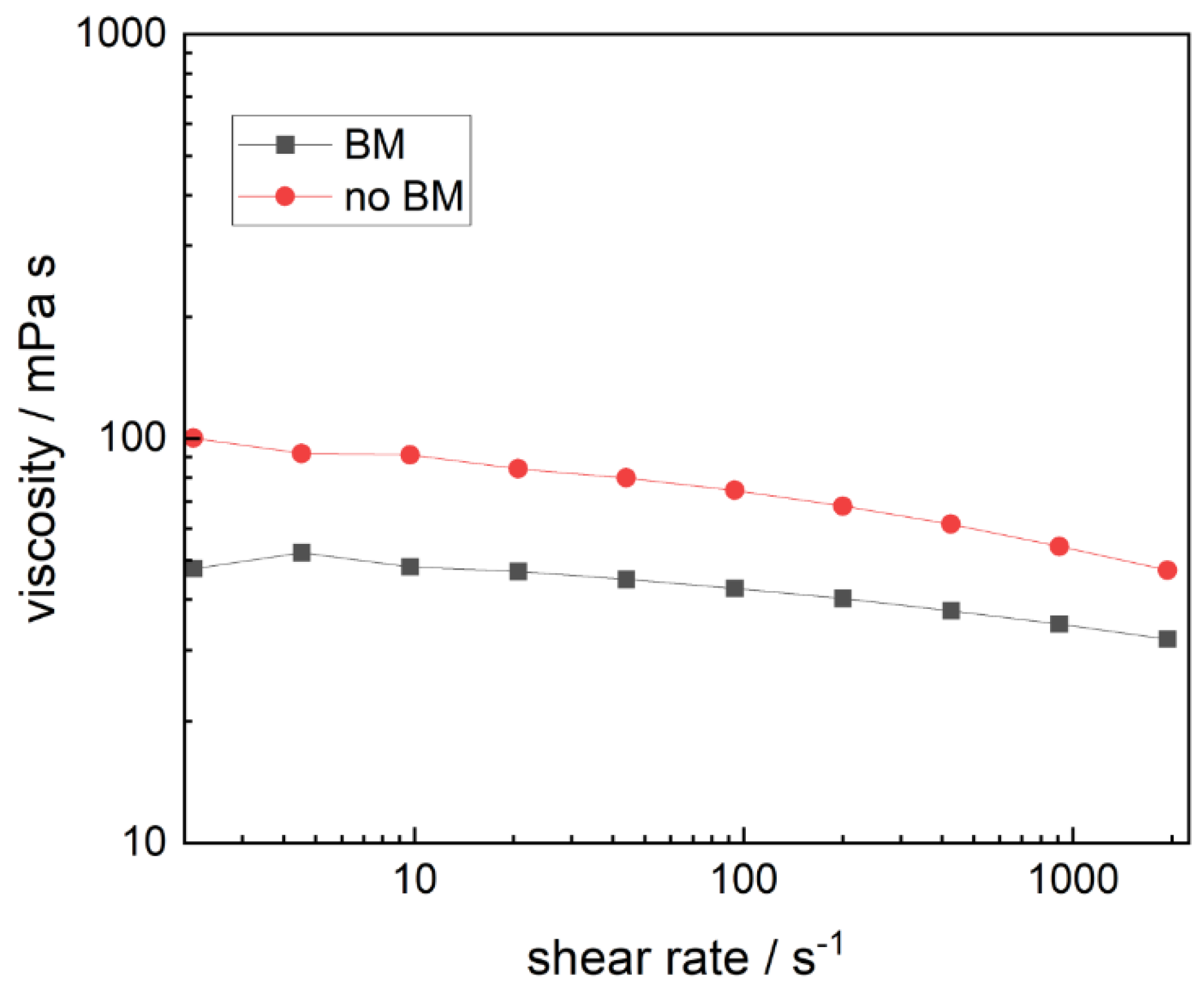
Figure 3.
Top surface of gravure printed cathodes by non-ball-milled (A,A’) and ball-milled (B,B’) LFP-based ink with permission from Ref. [56].
Figure 3.
Top surface of gravure printed cathodes by non-ball-milled (A,A’) and ball-milled (B,B’) LFP-based ink with permission from Ref. [56].

Figure 4.
Discharge specific capacity versus cycle number for gravure printed cathodes by non-ball-milled (no BM) and ball-milled (BM) LFP-based ink at constant C/10 rate (A) and variable rate (B) with permission from Ref. [56].
Figure 4.
Discharge specific capacity versus cycle number for gravure printed cathodes by non-ball-milled (no BM) and ball-milled (BM) LFP-based ink at constant C/10 rate (A) and variable rate (B) with permission from Ref. [56].
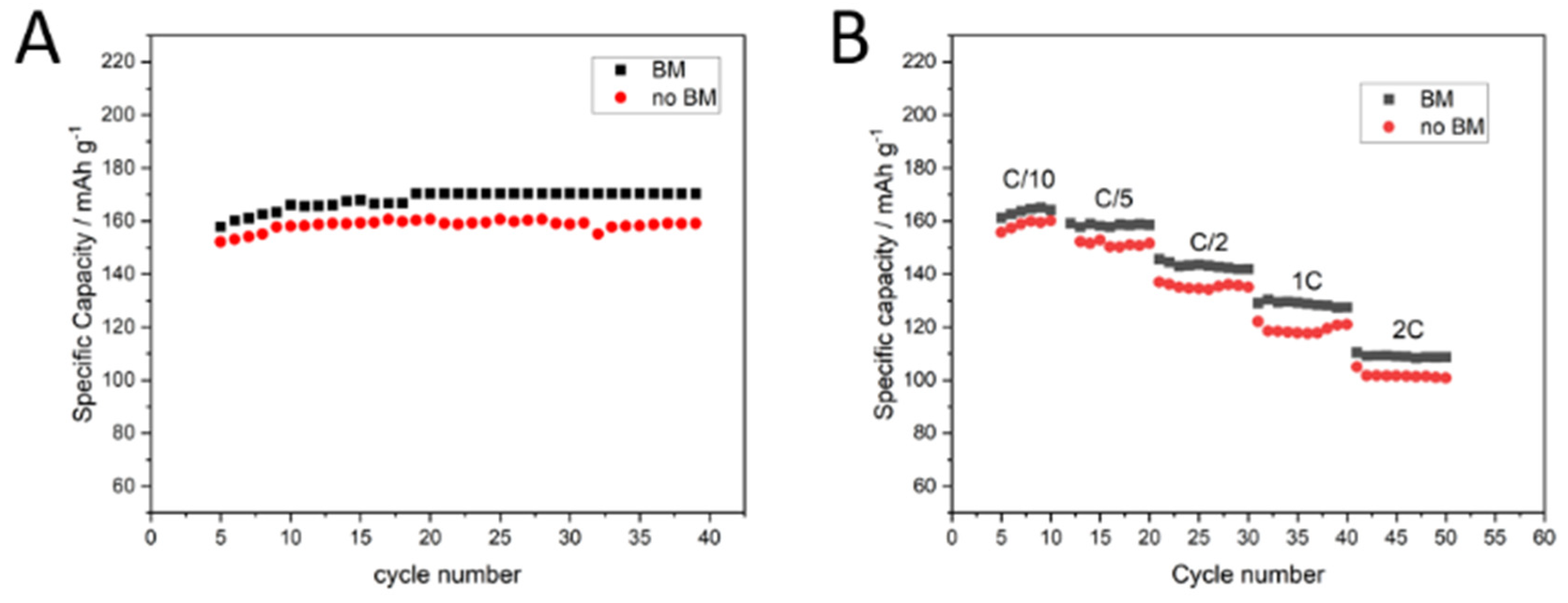
Figure 5.
Viscosity versus shear rate for non-ball-milled (no BM) and ball-milled (BM) LMO-based inks.
Figure 5.
Viscosity versus shear rate for non-ball-milled (no BM) and ball-milled (BM) LMO-based inks.
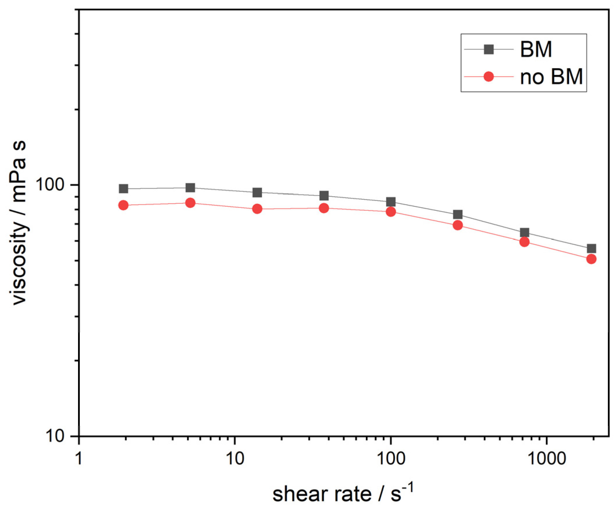
Figure 6.
Top surface of gravure printed layers by non-ball-milled (A,A’) and ball-milled (B,B’) LMO-based inks.
Figure 6.
Top surface of gravure printed layers by non-ball-milled (A,A’) and ball-milled (B,B’) LMO-based inks.
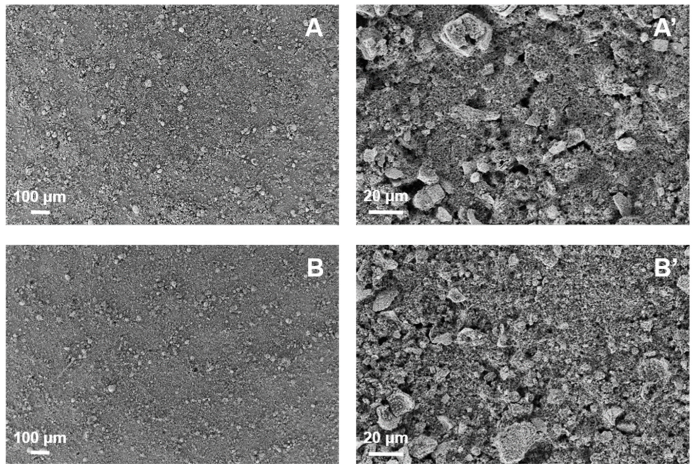
Figure 7.
SEM images of gravure printed CAM-based electrodes prepared using (a,a’) sonication, (b,b’) ball milling, and (c,c’) both techniques, with permission from Ref. [54].
Figure 7.
SEM images of gravure printed CAM-based electrodes prepared using (a,a’) sonication, (b,b’) ball milling, and (c,c’) both techniques, with permission from Ref. [54].

Figure 8.
Plot of specific capacity and Coulombic efficiency versus cycle number of 10 layered gravure-printed CAM-based electrodes cycled at C/5 (first cycle at C/20) with a limited upper cutoff voltage of 1.3 V. with permission from Ref. [54].
Figure 8.
Plot of specific capacity and Coulombic efficiency versus cycle number of 10 layered gravure-printed CAM-based electrodes cycled at C/5 (first cycle at C/20) with a limited upper cutoff voltage of 1.3 V. with permission from Ref. [54].

Figure 9.
SEM images of anode microstructure obtained by printing ball-milled graphite-based ink at different magnification with permission from Ref. [55]. (a) ×150 and (b) ×1400.
Figure 9.
SEM images of anode microstructure obtained by printing ball-milled graphite-based ink at different magnification with permission from Ref. [55]. (a) ×150 and (b) ×1400.
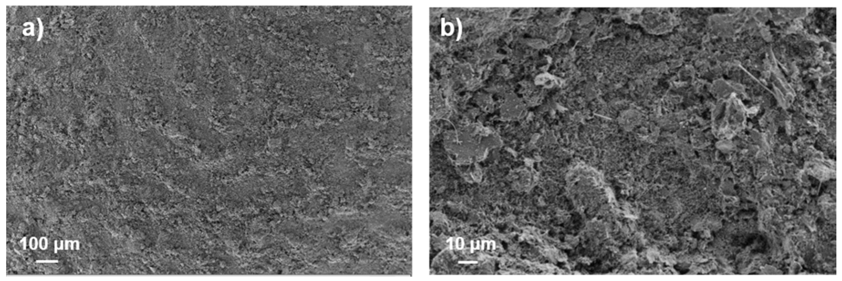
Figure 10.
Discharge-specific capacity of anode obtained by printing ball-milled graphite-based ink at (A) variable and (B) C/10 constant rates with permission from Ref. [55].
Figure 10.
Discharge-specific capacity of anode obtained by printing ball-milled graphite-based ink at (A) variable and (B) C/10 constant rates with permission from Ref. [55].

Table 1.
Summary of the main parameters involved in gravure printing.
| Gravure Cylinder | Process | Ink | Substrate |
|---|---|---|---|
| cell geometry | printing force | viscosity | surface energy |
| cell density | printing speed | surface tension | roughness |
| surface energy | web tension | solvent evaporation rate | porosity |
| diameter | solid content |
Table 2.
LFP-based ink characteristics, printing parameters, and printed layers characteristics.
| Ink | Printing | Electrode | ||||||||
|---|---|---|---|---|---|---|---|---|---|---|
| dry solid content [wt%] | ball milling | viscosity [mPa s] | surface tension [mN m−1] | printing speed [m s−1] | printing force [N] | Ca | number of layer | massloading [mg cm−2] | thickness [µm] | apparent density [g cm−3] |
| 15 | No | 74 | 30 | 0.6 | 700 | 1.5 | 10 | 1.8 | 20 ± 1 | 0.9 |
| 15 | Yes | 43 | 30 | 0.6 | 700 | 0.9 | 10 | 1.4 | 15 ± 1 | 0.9 |
Table 3.
LMO-based ink characteristics, printing parameters, and printed layer characteristics.
| Ink | Printing | Electrode | ||||||||
|---|---|---|---|---|---|---|---|---|---|---|
| dry solid content [wt%] | ball milling | viscosity [mPa s] | surface tension [mN m−1] | printing speed [m s−1] | printing force [N] | Ca | number of layer | mass loading [mg cm−2] | thickness [µm] | apparent density [g cm−3] |
| 18 | No | 78 | 42 | 0.6 | 700 | 1.1 | 7 | 0.7 | 19 ± 4 | 0.4 |
| 18 | Yes | 86 | 42 | 0.6 | 700 | 1.2 | 7 | 2.0 | 24 ± 2 | 0.8 |
Table 4.
CAM-based ink characteristics, printing parameters, and printed layer characteristics.
| Ink | Printing | Electrode | ||||||||
|---|---|---|---|---|---|---|---|---|---|---|
| dry solid content [wt%] | ball milling | viscosity [mPa s] | surface tension [mN m−1] | printing speed [m s−1] | printing force [N] | Ca | number of layer | mass loading [mg cm−2] | thickness [µm] | apparent density [g cm−3] |
| 14 | Yes | 100 | 30 | 0.6 | 700 | 2.0 | 10 | 1.3 | 22 ± 2 | 0.6 |
| 14 | Yes | 100 | 30 | 0.6 | 700 | 2.0 | 15 | 1.7 | 30 ± 3 | 0.6 |
Table 5.
Graphite-based ink characteristics, printing parameters, and printed layer characteristics.
Table 5.
Graphite-based ink characteristics, printing parameters, and printed layer characteristics.
| Ink | Printing | Electrode | ||||||
|---|---|---|---|---|---|---|---|---|
| dry solid content [wt%] | ball milling | surface tension [mN m−1] | printing speed [m s−1] | printing force [N] | number of layer | mass loading [mg cm−2] | thickness [µm] | apparent density [g cm−3] |
| 18 | Yes | 42 | 0.6 | 700 | 6 | 0.9 | 18 | 0.5 |
Table 6.
Comparative table of LiB electrodes produced by different printing techniques.
| Printing Technique | ELECTRODE TYPE | Active Material | Binder | Solvent | Cell Type | Specific Capacity [mAh g−1] | Ref. |
|---|---|---|---|---|---|---|---|
| gravure | cathode | LFP | CMC | water + 2-propanol | half | 168 @ C/10 | [56] |
| gravure | cathode | LMO | CMC | water + 2-propanol | half | 110 @ C/10 | [57] |
| gravure | anode | CAM | CMC | water + 2-propanol | half | 600 @ C/10 | [54] |
| gravure | anode | graphite | CMC | water + 2-propanol | half | 355 @ C/10 | [55] |
| gravure | anode | graphite | PVDF/PVDF + PVP | NMP | half | 340 | [62,63] |
| screen printing | cathode | LFP | PVDF | NMP | half | 48 @ 5C | [58] |
| aerosol | cathode | LFP | Kynar | 2-butanol | half | 151 @ C/15 | [60] |
| spray | cathode | LFP | CMC | water + 2-propanol | full | 150 @ 4A g−1 | [61] |
| screen printing | anode | graphite | PVDF | NMP | full | 81 | [59] |
Disclaimer/Publisher’s Note: The statements, opinions and data contained in all publications are solely those of the individual author(s) and contributor(s) and not of MDPI and/or the editor(s). MDPI and/or the editor(s) disclaim responsibility for any injury to people or property resulting from any ideas, methods, instructions or products referred to in the content. |
© 2023 by the authors. Licensee MDPI, Basel, Switzerland. This article is an open access article distributed under the terms and conditions of the Creative Commons Attribution (CC BY) license (https://creativecommons.org/licenses/by/4.0/).
Share and Cite
MDPI and ACS Style
Montanino, M.; Sico, G. Gravure Printing for Lithium-Ion Batteries Manufacturing: A Review. Batteries 2023, 9, 535. https://doi.org/10.3390/batteries9110535
AMA Style
Montanino M, Sico G. Gravure Printing for Lithium-Ion Batteries Manufacturing: A Review. Batteries. 2023; 9(11):535. https://doi.org/10.3390/batteries9110535
Chicago/Turabian StyleMontanino, Maria, and Giuliano Sico. 2023. "Gravure Printing for Lithium-Ion Batteries Manufacturing: A Review" Batteries 9, no. 11: 535. https://doi.org/10.3390/batteries9110535
Note that from the first issue of 2016, this journal uses article numbers instead of page numbers. See further details here.