
Highly Flexible Stencil Printed Alkaline Ag2O-Zn Battery for Wearable Electronics
by
 , ,
, ,
Akash Kota
1,* ,
,
Lenin W. Kum
1,
Kavya Vallurupalli
2,
Ashish Gogia
1, 
Amy T. Neidhard-Doll
1 and
Vamsy P. Chodavarapu
1 1
Department of Electrical and Computer Engineering, University of Dayton, Dayton, OH 45469, USA
2
Department of Civil, Architectural, and Environmental Engineering, Missouri University of Science and Technology, Rolla, MO 65409, USA
*
Author to whom correspondence should be addressed.
Batteries 2022, 8(7), 74; https://doi.org/10.3390/batteries8070074
Submission received: 11 June 2022
/
Revised: 10 July 2022
/
Accepted: 13 July 2022
/
Published: 16 July 2022
(This article belongs to the Special Issue Zn-Based Batteries: Recent Progresses and Challenges)
Abstract
:Flexible power sources such as batteries are essential to realize wearable and conformable electronic devices. The mechanical stability of the electrodes plays an important role in determining the overall flexibility of the battery. Styrene block copolymers-based elastomers have the potential to be used as binder materials in the electrodes for retaining their structural integrity under flexing during regular use. In this work, we demonstrate a stencil-printed flexible primary Ag2O-Zn battery on a nonconductive nylon mesh substrate that uses styrene-butadiene rubber as the anodic binder. A polyacrylic acid-based alkaline polymer gel is used as an electrolyte. The flexible alkaline battery achieved discharge capacities of and without and with a bend radius of 0.8 , respectively, under a constant current load condition of .
1. Introduction
Flexible batteries are promising power sources for the next generation of electronics such as body conformal sensors [1], wearable biosensors [2,3], thin-film transistors [4], implantable medical devices [5], wearable memories [6], and foldable printed circuit boards [7]. In a flexible battery, the overall flexibility depends on the mechanical properties of substrate, electrodes, electrolytes, and packaging. To demonstrate flexible batteries, two different approaches have been used. In the first approach, the electrochemically active materials of a battery are loaded onto a flexible conductive yarn to form one-dimensional (1D) fiber electrodes. Carbon nanotube (CNT)-based conductive yarns are used to fabricate 1D battery electrodes. Using this approach, a variety of 1D flexible lithium-ion, MnO2-Zn, and Ag-Zn batteries have been demonstrated [8,9,10,11,12,13,14]. In the second approach, the electrode materials of the battery are loaded onto the scaffold of flexible two-dimensional (2D) or three-dimensional (3D) substrates. The substrates can be either electrically conductive or nonconductive. In the former case, a carbon cloth is typically used as the host matrix. In the latter case, the non-conductive substrate can be made of either a fabric or a polymer. To load the active materials conformally onto the carbon cloth, methods such as electrodeposition, carbonization, and chemical bath deposition have been used. Using these methods, 3D flexible Ni-Zn and Ni-Fe batteries have been reported [15,16]. Printing methods such as screen printing and dip coating are used to design 2D flexible batteries using nonconductive substrates. Using the flexible polymer and textile substrates, a variety of 2D alkaline MnO2-Zn and Ag2O-Zn batteries have been demonstrated [17,18,19,20,21,22].
Primary flexible batteries with emphasis on minimizing toxicity and a low-cost fabrication process have mostly used zinc as the anode, with a metal oxide such as MnO2 and Ag2O as the active cathode material. In wearable electronic applications, aqueous electrolyte-based alkaline MnO2-Zn and Ag2O-Zn chemistries are preferred over flammable inorganic electrolyte-based lithium-ion chemistries due to biosafety reasons. For instance, lithium hexafluorophosphate (LiPF6), which is used as an inorganic electrolyte in a lithium-ion battery, is flammable [23]. Furthermore, unlike lithium-ion chemistry, alkaline chemistries are not air sensitive. Therefore, for alkaline chemistries, an inert atmosphere is not required during the fabrication process. However, several challenges are involved in the fabrication of flexible alkaline batteries because of the compatibility issues between different layers of a battery, the thermal budget imposed by textile and plastic substrates, and stability issues during bending [24]. To improve the mechanical stability of electrodes in a flexible battery, one of the approaches is to design very thin electrodes, thereby reducing the strain on the electrode during bending [25]. This approach will confine the cell capacity because it limits the quantity of active material available in the electrode. Another approach is to use elastic polymers as binder materials during the synthesis of electrode inks. Styrene block copolymers-based elastomers such as styrene–isoprene–styrene (SIS), styrene–butadiene rubber (SBR), styrene–ethylene–butadiene–styrene (SEBS), and styrene–ethylene–isoprene–styrene (SIBS) have the potential to be used as the binder materials in flexible electrode inks. There are two types of printed battery architectures: the planar and the vertical type. In planar type architecture, the battery electrodes are in the same plane with a separator or electrolyte connecting the top surfaces of the electrodes. As the separation distance between the two electrodes varies from few mm to cm, planar batteries typically suffer from high impedance. This leads to non-uniform current distributions [26]. The energy density of the planar battery is also low, due to a large fraction of electrolyte and encapsulation layers. On the other hand, in the vertical type, the electrodes are aligned face-to-face. This is an ideal architecture that minimizes the electrode separation distance and affords high energy density due to the more compact volume. Batteries printed in the vertical configuration allows for a more uniform current distribution, which can potentially reduce dendrite or filament formation in Ag2O-Zn batteries. Using SIS as the electrode binder, a stretchable planar Ag2O-Zn battery has been demonstrated on a textile substrate [22]. In our previous work, we demonstrated a 2D planar primary Ag2O-Zn battery on a textile substrate using polyvinylidene fluoride (PVDF), which is an inelastic polymer as the electrode binder [27]. To overcome the drawbacks in the planar printed Ag2O-Zn batteries, in the current work, we report a 2D printed flexible vertically assembled primary Ag2O-Zn battery, using SBR elastomer as the anodic binder. In a printed battery, each individual component (i.e., current collector, anode, cathode, electrolyte, and separator) should ideally be printable. In this work, with the exception of the separator, all the other components of the battery are printed using a low-cost stencil printing method. To improve the discharge capacity of the battery under bending conditions, a flexible thick non-printed polyethylene sheet is used as the separator material. The demonstrated battery achieved discharge capacities of and without and with a bend radius of 0.8 , respectively, under a constant current load condition of .
2. Materials and Methods
2.1. Materials Used
Substrate: A mesh size nylon mesh (McMaster-Carr, Cleveland, OH, USA, serial number: 9318T95) is used as the flexible substrate to print different layers of the battery.
Current Collector: The current collector layer is printed using silver ink (Creative Materials, Ayer, MA, USA, serial number: 127-07). The obtained silver ink is used without any further modifications.
Cathode: To prepare the silver oxide ink, 5 wt% polyethylene oxide (PEO) (Sigma-Aldrich, Milwaukee, WI, USA, serial number: 182028) binder is used. The mechanical strength of a polymer depends on its average molecular weight . The of PEO typically varies from 12,000 to 600,000 . For the stencil printing process, PEO with higher exhibits good mechanical strength [26]. Therefore, PEO having 600,000 is selected. To prepare 10 g of 5 wt% PEO gel, 0.5 g of PEO is dissolved in 9.5 g of distilled water. To prepare a homogenized PEO gel, it is stirred for 4 h at room temperature on a magnetic stirrer at 500 rpm at room temperature. The silver oxide ink contains 95 wt% Ag2O (Sigma-Aldrich, serial number: 221163) as the active material and 5wt% PEO as the binder. To prepare 1 g of 95:5 silver oxide ink, 950 mg of Ag2O is added to 1 g of 5 wt% PEO binder. To obtain a homogeneous Ag2O ink, it is mixed for 15 min in a Thinky AR-100 conditioning mixer.
Anode: To prepare the zinc ink, 1.6 wt% SBR (MTI, USA, serial number: EQ-LIB-SBR) binder is used. To dissolve the SBR, ethylene glycol (EG) (Sigma-Aldrich, Milwaukee, USA, serial number: 102466) is used as the solvent. The zinc ink contains 70 wt% Zn (Sigma-Aldrich, Milwaukee, WI, USA, serial number: 209988), 7 wt% zinc oxide (ZnO) (Sigma-Aldrich, Milwaukee, WI, USA, serial number: 205532), 11 wt% bismuth oxide (Bi2O3) (Sigma-Aldrich, Milwaukee, WI, USA, serial number: 223891), 1.5 wt% SBR, and 10.5 wt% EG. To prepare 1 gm of zinc ink, 700 mg of Zn, 70 mg of ZnO, 110 mg of Bi2O3, and 15 mg of SBR are added to 105 mg of EG. The approximate size of the Zn and ZnO particles is <10 and <5 , respectively. The Zn ink is also homogeneously mixed for 15 min using the AR-100 conditioning mixer.
Separator: A flexible thick non-printed polyethylene (ENTEK, Lebanon, OR, USA) sheet is used as the separator material.
Electrolyte: The gel electrolyte is prepared by adding 1.5 wt% of polyacrylic acid (PAA) (Sigma-Aldrich, Milwaukee, WI, USA, serial number: 306215) in ZnO saturated 8 M potassium hydroxide (KOH) (Sigma-Aldrich, Milwaukee, WI, USA, serial number: 484016) solution. The selected PAA has a 1,250,000 . To prepare 8 M KOH solution, 4.48 g of KOH is dissolved in 10 mL of distilled water. Appropriate amount of ZnO is added to 8 M KOH and stirred until saturation. Excess ZnO is removed by filtration. To prepare 5 g of 1.5 wt% PAA, 0.075 g of PAA is added to 4.925 g of ZnO saturated 8 M KOH solution.
Encapsulation: A 150 thick polyethylene (Thermwell Products Co, Mahwah, NJ, USA, serial number: P1025/6W) sheet is used an encapsulation material.
2.2. Battery Fabrication Procedure
The battery fabrication process is as follows. First, two nonconductive nylon mesh substrates of size 6 cm 6 cm are obtained. Using a 350 thick polyamide-nylon 6 (PA 6) (Goodfellow, Coraopolis, PA, USA, serial number: AM301350) stencil, on one side of the mesh, the silver current collector layer of size 4 cm 1.5 cm is printed on each of the substrates. To evaporate the residual solvent in the silver ink, the printed current collector layers are dried at 100 °C in a vacuum oven for 30 min. After drying, on the underside of the mesh, the silver oxide and zinc electrodes are printed. Using a 350 thick PA 6 stencil, electrodes of size 2.5 cm 1.5 cm are printed onto the underside of the individual current collector layers. The printed silver oxide electrode is dried in air for 12 h, while the zinc electrode is dried in a vacuum oven at 70 °C for 1 h. After drying, the weight of Ag2O in a silver oxide mesh electrode is found out to be approximately 29 mg. To estimate the theoretical capacity of a cathode, it is essential to determine the weight of active material present in it. The theoretical calculations to determine the weight of Ag2O in a silver oxide electrode printed on a non-conductive substrate are reported previously [26]. Similarly, the dry weight of zinc electrode is found out to be 0.2 g. Using the polyethylene sheet, the mesh electrodes are used to assemble the flexible battery in the following order: anode, gel electrolyte, separator, and cathode to make a pouch cell. The PAA-based gel electrolyte is printed on the zinc electrode using a 500 thick polyethylene terephthalate (PET) stencil. A CO2 laser (Boss Laser, Sanford, FL, USA, serial number: LS1416) is used to engrave the stencils with required patterns. The battery fabrication steps are illustrated in a flow chart shown in Figure 1a. The cross-sectional view of the corresponding printed layer at each fabrication step is shown in Figure 1b. The cross-sectional view of an assembled Ag2O-Zn pouch cell is shown in Figure 1c.
2.3. Characterization Methods
The surfaces of different printed layers are characterized using high resolution scanning electron microscope (HRSEM) (Hitachi High Technologies America Inc., Dallas, TX, USA, serial number: S-4800). The elemental composition of the electrodes is determined using environmental scanning electron microscope (ESEM) coupled with energy dispersive X-ray spectroscopy (EDX) (Zeiss, White Plains, NY, USA, serial number: Zeiss EVO50 with EDAX Genesis 2000). The ionic conductivity of the gel electrolyte is determined by performing electrochemical impedance spectroscopy (EIS) using Solartron impedance analyzer (Ametek Scientific Instruments, Oak Ridge, TN, USA, serial number: Solartron 1260). Rheology experiments are performed to determine the viscosity, storage, and loss moduli of the gel electrolyte using Anton Paar rheometer (Anton Paar, Ashland, VA, USA, serial number: MCR302) in concentric cylinder configuration. The battery characterization experiments are performed using Neware battery cycler (Neware Technology, Shenzhen, China, serial number: BTS 4000).
3. Results
The macroscopic images of different printed layers are shown in Figure 2a–c. The image of a printed Ag2O-Zn battery assembled in a pouch is shown in Figure 2d. Figure 2e shows the image of an assembled battery when flexed to a bend radius of 0.2 cm.
3.1. HRSEM Characterization
The top surface of the printed silver current collector and the silver oxide and zinc layers are characterized using HRSEM. The surface morphology of the printed layers is shown in Figure 3a–c. The cross-sectional HRSEM images of the mesh-embedded Ag2O and Zn electrodes are shown in Figure 3d,e, respectively. From Figure 3a it can be observed that the surface of the stencil printed silver layer is conformal and it occupies the void spaces in the mesh substrate. The presence of unoccupied voids will increase the electrical resistance between the electrode and the silver current collector layer. Figure 3b,c shows the surface morphology of the Ag2O and Zn layers, confirming a tight and densely distributed particle structure on the surface. Figure 3d,e shows the existence of good electrical contact between Ag2O and Zn with the silver current collector layer. The dotted line in Figure 3d,e highlights the cross-section of mesh between the current collector and electrode layers.
3.2. EDX Characterization
To determine the elemental composition of the electrodes, EDX analysis has been performed. The EDX spectrum of the silver oxide and Zinc electrodes is shown in Figure 4a,b, respectively.
The EDX spectrum of the silver oxide electrode confirms the presence of silver and oxygen. Similarly, the EDX spectrum of the zinc electrode reveals the presence of zinc, oxygen, and bismuth. Before obtaining the EDX spectrum, to enhance the electrical conductivity of the silver oxide and zinc electrode samples, they are sputtered with gold. Therefore, in the EDX spectrum of both the silver oxide and zinc electrodes, a corresponding gold peak arises. In Figure 4b, the oxygen peak arises due to the presence of zinc oxide and bismuth oxide in the zinc electrode. The elemental distribution maps of the silver oxide and zinc electrodes are shown in Figure 5 and Figure 6, respectively.
3.3. EIS Characterization
EIS tests are performed to study the effect of PAA concentration on the gel electrolyte used in the battery. The ionic conductivity of the gel electrolyte has been obtained for different PAA concentrations. The PAA concentrations are varied from 1 wt% to 2 wt%. To perform the EIS experiment, the PAA-based gel electrolyte is loaded into a CR2032 coin cell with stainless steel (SS) electrodes. The area of the SS electrodes is 2.85 . A thick polyethylene sheet is used as the separator. Using a 5 mL pipette, approximately 3 mL of gel electrolyte is drop casted on top of the SS electrode. The components of the coin cell are assembled in the following order: SS electrode, gel electrolyte, separator, and SS electrode. After preparing the coin cell, it is connected to a Solartron impedance analyzer to obtain the EIS plots. Using a 50 alternating current (AC) voltage with a frequency ranging from 10 Hz to 1 MHz, EIS plots are obtained by varying the wt% of PAA in the gel electrolyte. The EIS plot of the gel electrolyte with 1.5 wt% PAA is shown in Figure 7a. The effect of PAA wt% on the ionic conductivity of the gel electrolyte is shown in Figure 7b. The real impedance () and imaginary impedance () are plotted on the and axes, respectively. The -intercept on the plot is taken as the electrolyte resistance () and is converted to ionic conductivity using (1)
where, is the thickness of the separator and is the area of the SS electrode.
From Figure 7a it can be observed that the resistance of the electrolyte is found out to be 6.085 . Using (1), the ionic conductivity can be calculated as . From Figure 7b it can be observed that as the wt% of PAA increases from 1 wt% to 1.5 wt%, the ionic conductivity increases from to , respectively. This is expected because the absorption of the aqueous KOH electrolyte by PAA depends on its . PAA with a higher results in a higher absorption of KOH. Therefore, the ionic conductivity increases with an increase in the wt% of PAA. However, when the wt% of PAA further increased from 1.5 wt% to 2 wt%, the ionic conductivity decreased from to . Hence, 1.5 wt% PAA is considered to prepare the gel electrolyte. The ionic conductivity can be further increased by utilizing salts such as potassium polyacrylate (PAAK) and poly (acrylic acid-co-maleic acid) in the gel electrolyte [28,29].
3.4. Rheology Characterization
Rheology experiments are performed to evaluate the effects of printing and flexing on the PAA-based gel electrolyte. The steady state rheological measurements are obtained using a co-axial concentric cylinder rheometer. The serrated inner cylinder of diameters 26.7 mm and a sandblasted outer cylinder with 28.9 mm is used to avoid slippage during shearing. The gel electrolyte is pre-sheared at for 120 s and a logarithmic shear rate sweep from 0.01 to 100 is applied for 60 s. Rheology tests are performed on 1 wt%, 1.5 wt%, and 2 wt% PAA in ZnO-saturated 8 M KOH. All the tests are performed at . The viscosity versus shear rate curves are shown in Figure 8a. Figure 8a shows that at low shear rates, the gel electrolyte exhibits a high viscosity. The viscosity of the gel electrolyte plays an important role in the development of packaging protocols for the printed alkaline batteries. The high viscous gels can simplify the packaging and prevent the leakages in the event of cell rupture. Furthermore, in Figure 8a, as the shearing rate increases, the viscosity decreases. Hence, it can be concluded that a shear thinning behavior is observed for all the three different gel electrolytes. The shear thinning behavior of the gel electrolyte indicates that it could be printed using extrusion- or dispenser-based printers. The high viscosity at a low shear rate suggests a high shape retaining ability after extrusion as well as leakage prevention [30], while the low viscosity at a high shear rate can indicate that a low energy is needed for the extrusion of the gel electrolyte.
The effect of flexing to different bend radii on the gel electrolyte is studied by performing strain sweep experiments. Oscillatory strain sweep experiments are performed on 1.5 wt% PAA in ZnO-saturated 8 M KOH at a 1 Hz frequency with strain rates ranging from 0.050% to 100% on a logarithmic scale. The obtained results are shown in Figure 8b. The strain sweep is carried out at a 1 Hz frequency to simulate the bending behavior within the battery, when the battery is flexed from a flat position once per second. The storage modulus indicates an elastic (solid-like) behavior while the loss modulus indicates a viscous (liquid-like) behavior of the gel electrolyte. From Figure 8b, it can be observed that both the storage and loss moduli are constant within the strain range of 0.05% to 6%. The constant values of storage and loss moduli within this range indicate a linear viscoelastic behavior for the gel electrolyte. This behavior suggests that the structural integrity of the gel electrolyte is maintained during flexing.
3.5. Discharge Characteristics
The discharge profiles of the battery under constant current load conditions of 0.1 , 0.5 , and 1 when no bending is applied are shown in Figure 9. Without bending, the voltage of the battery declined from 1.5 V to 0.7 V in roughly 24 h, 8 h, and 4 h while discharging the battery at 0.1 mA, 0.5 mA, and 1 mA, respectively. This is expected because discharging the battery at higher load currents will decrease the discharge duration.
The performance of the battery during flexing is characterized by bending the battery around cylinders with diameters of 1.25 cm and 0.8 cm, while discharging at 0.1 . The discharge characteristics are shown in Figure 10.
From Figure 10a, it can be observed that under the flat case, i.e., without bending the battery, the discharge voltage dropped from 1.5 V to 0.7 V in 24 h. Compared to the flat case, as the bend radii is decreased from 1.25 cm to 0.8 cm, the discharge voltage dropped from 1.5 V to 0.7 V in approximately 18 h and 16 h, respectively. Figure 10b shows the plot of discharge voltage as a function of discharge capacity under flat and flexing conditions. From Figure 10b, it can be observed that without bending, the demonstrated flexible battery achieved a discharge capacity of 2.5 . Under flexing conditions, as the bend radius is decreased from 1.25 cm to 0.8 cm, the discharge capacity is dropped from 1.75 to 1.6 , respectively. With an active electrode area of 1.0 in. 0.5 in. (3.2 ), without bending, and with a bend radius of 1.25 cm and 0.8 cm, the corresponding areal capacities are 0.78 , 0.55 , and 0.50 , respectively. The dry mass of Ag2O in the silver oxide electrode is 29 mg. With reference to the active mass, without bending, and with a bend radius of 1.25 cm and 0.8 cm, the corresponding specific capacities are 86.21 , 60.34 , and 55.17 , respectively. In Table 1, the battery capacities achieved under different test conditions are illustrated.
Compared to the flat case, when the battery is flexed to different radii of curvature, a decrease in the discharge capacity is observed. For instance, in Figure 10b, compared to the flat case when the bend radius is decreased to 0.8 cm, the discharge capacity is decreased from 0.78 to 0.50 . This is because decreasing the battery bend radius to 0.8 cm has ultimately led to the structural disintegration of the zinc electrode. Furthermore, after 10 bending cycles with a minimum bend radius of 0.8 cm, delamination of the zinc electrode from the mesh substrate is observed, which can be attributed to the styrene content in the SBR binder. The percentage of styrene in the SBR binder used in the current work is in the range of 23% to 25% and is not elastic enough to withstand the strain incurred during the bending cycles. The mechanical properties of the SBR binder can be improved by increasing the styrene content [31]. The effects of structural disintegration and delamination from the mesh substrate can be avoided by using an SBR binder that has a styrene content greater than 25% in the Zn electrode. However, under flexing conditions, the discharge capacity achieved by the demonstrated flexible battery is superior to other alkaline batteries demonstrated using SBR as the anodic binder. For instance, the reported discharge capacity of the printed primary Zn-MnO2 battery, which used SBR as the anodic binder and polyvinyl alcohol (PVA)/cellulose as the separator material, is 0.8 [20]. Furthermore, the minimum bend radii achieved by the demonstrated flexible battery is 0.8 cm, which is smaller than the minimum bend radii of the currently available commercial Zn-MnO2 flexible battery, which is 3.5 cm [32]. For wearable electronic devices, the power requirements can vary from low voltage and high amperage to relatively high voltage and low amperage. The demonstrated flexible battery design can be readily customized to power wearable devices with various energy and power requirements.
4. Conclusions
In this work, a stencil printed flexible primary Ag2O-Zn battery is demonstrated on a non-conductive nylon mesh substrate using SBR as the anodic binder. The HRSEM characterization of the printed layers shows the existence of good electrical contact between the Ag2O and Zn with the silver current collector layer. The elemental distribution maps obtained by performing the EDX characterization reveal that the individual elements in the Ag2O and Zn electrodes are uniformly distributed. To improve the mechanical stability of the electrolyte in the battery, a PAA-based gel electrolyte is used. The ionic conductivity tests reveal that gel electrolyte with a 1.5 wt% PAA achieved the highest ionic conductivity. Rheological tests demonstrate the shear thinning behavior of the gel electrolyte, which suggests its use in the dispenser- or extrusion-based print systems. The strain sweep experiments reveal that the gel electrolyte with a 1.5 wt% PAA has a linear viscoelastic region in the strain sweep range of 0.05% to 6%. This behavior suggests that the structural integrity of the gel electrolyte is maintained during flexing. The discharge characteristics reveal that without flexing, the demonstrated flexible battery achieved a discharge capacity of 2.5 . Under flexing conditions, with a minimum bend radius of 0.8 cm, the achieved discharge capacity is 1.6 . Compared to the flat case, a decrease in the discharge capacity has been observed under flexing conditions. This can be avoided by increasing the elasticity of the polymer used in the anodic binder. Repeated bending cycles with a minimum bend radius of 0.8 cm has resulted in the delamination of the zinc anode from the mesh substrate that can be attributed to the styrene content of the SBR binder. The effects of structural disintegration and delamination of the zinc anode under different flexing conditions can be avoided by using an SBR binder that has a styrene content greater than 25%. The achieved discharge capacities under flexing conditions are superior to other alkaline batteries demonstrated using SBR as the anodic binder. The demonstrated flexible battery can find its use in powering wearable electronic devices.
Author Contributions
Conceptualization, A.K.; methodology, A.K., L.W.K., K.V.; validation, A.K.; formal analysis, A.K.; investigation, A.K.; visualization, A.K. and A.G.; resources, A.T.N.-D. and V.P.C.; data curation, A.K. and K.V.; writing—original draft preparation, A.K.; writing—review and editing, A.K., L.W.K., K.V., A.G., A.T.N.-D., and V.P.C.; supervision, A.T.N.-D. and V.P.C.; project administration, A.T.N.-D. and V.P.C.; funding acquisition, A.T.N.-D. and V.P.C. All authors have read and agreed to the published version of the manuscript.
Funding
The authors would like to thank the School of Engineering at the University of Dayton for providing the funding to pursue the research.
Institutional Review Board Statement
Not applicable.
Informed Consent Statement
Not applicable.
Data Availability Statement
Research data presented in this article are available on request from the corresponding author.
Conflicts of Interest
The authors declare no conflict of interest.
References
- Ershad, F.; Thukral, A.; Yue, J.; Comeaux, P.; Lu, Y.; Shim, H.; Sim, K.; Kim, N.; Rao, Z.; Guevara, R. Ultra-Conformal Drawn-on-Skin Electronics for Multifunctional Motion Artifact-Free Sensing and Point-of-Care Treatment. Nat. Commun. 2020, 11, 3823. [Google Scholar] [CrossRef] [PubMed]
- Kim, J.; Campbell, A.S.; de Ávila, B.E.; Wang, J. Wearable Biosensors for Healthcare Monitoring. Nat. Biotechnol. 2019, 37, 389–406. [Google Scholar] [CrossRef] [PubMed]
- Kim, H.; Kim, Y.; Mahmood, M.; Kwon, S.; Zavanelli, N.; Kim, H.S.; Rim, Y.S.; Epps, F.; Yeo, W. Fully Integrated, Stretchable, Wireless Skin-Conformal Bioelectronics for Continuous Stress Monitoring in Daily Life. Adv. Sci. 2020, 7, 2000810. [Google Scholar] [CrossRef] [PubMed]
- Whiting, G.L.; Arias, A.C. Chemically Modified Ink-Jet Printed Silver Electrodes for Organic Field-Effect Transistors. Appl. Phys. Lett. 2009, 95, 328. [Google Scholar] [CrossRef]
- Kim, D.; Kim, Y.; Amsden, J.; Panilaitis, B.; Kaplan, D.L.; Omenetto, F.G.; Zakin, M.R.; Rogers, J.A. Silicon Electronics on Silk as a Path to Bioresorbable, Implantable Devices. Appl. Phys. Lett. 2009, 95, 133701. [Google Scholar] [CrossRef]
- Li, J.; Zhang, C.; Duan, L.; Zhang, L.M.; Wang, L.D.; Dong, G.F.; Wang, Z.L. Flexible Organic Tribotronic Transistor Memory for a Visible and Wearable Touch Monitoring System. Adv. Mater. 2016, 28, 106–110. [Google Scholar] [CrossRef]
- Eshkeiti, A.; Reddy, A.S.; Emamian, S.; Narakathu, B.B.; Joyce, M.; Joyce, M.; Fleming, P.D.; Bazuin, B.J.; Atashbar, M.Z. Screen Printing of Multilayered Hybrid Printed Circuit Boards on Different Substrates. IEEE Trans. Compon. Packag. Manuf. Technol. 2015, 5, 415–421. [Google Scholar] [CrossRef]
- Lee, J.M.; Choi, C.; Kim, J.H.; de Andrade, M.J.; Baughman, R.H.; Kim, S.J. Biscrolled Carbon Nanotube Yarn Structured Silver-Zinc Battery. Sci. Rep. 2018, 8, 11150. [Google Scholar] [CrossRef]
- Kwon, Y.H.; Woo, S.; Jung, H.; Yu, H.K.; Kim, K.; Oh, B.H.; Ahn, S.; Lee, S.; Song, S.; Cho, J. Cable-type Flexible Lithium Ion Battery Based on Hollow Multi-helix Electrodes. Adv. Mater. 2012, 24, 5192–5197. [Google Scholar] [CrossRef]
- Rao, J.; Liu, N.; Li, L.; Su, J.; Long, F.; Zou, Z.; Gao, Y. A High Performance Wire-Shaped Flexible Lithium-Ion Battery Based on Silicon Nanoparticles within Polypyrrole/Twisted Carbon Fibers. RSC Adv. 2017, 7, 26601–26607. [Google Scholar] [CrossRef]
- Ren, J.; Zhang, Y.; Bai, W.; Chen, X.; Zhang, Z.; Fang, X.; Weng, W.; Wang, Y.; Peng, H. Rücktitelbild: Elastic and Wearable Wire-Shaped Lithium-Ion Battery with High Electrochemical Performance. Angew. Chem. 2014, 126, 8092. [Google Scholar] [CrossRef]
- Wang, K.; Zhang, X.; Han, J.; Zhang, X.; Sun, X.; Li, C.; Liu, W.; Li, Q.; Ma, Y. High-Performance Cable-Type Flexible Rechargeable Zn Battery Based on MnO2@ CNT Fiber Microelectrode. ACS Appl. Mater. Interfaces 2018, 10, 24573–24582. [Google Scholar] [CrossRef] [PubMed]
- Zhang, Y.; Bai, W.; Ren, J.; Weng, W.; Lin, H.; Zhang, Z.; Peng, H. Super-Stretchy Lithium-Ion Battery Based on Carbon Nanotube Fiber. J. Mater. Chem. A 2014, 2, 11054–11059. [Google Scholar] [CrossRef]
- Zhang, C.; Zhu, J.; Lin, H.; Huang, W. Flexible Fiber and Fabric Batteries. Adv. Mater. Technol. 2018, 3, 1700302. [Google Scholar] [CrossRef]
- Liu, J.; Guan, C.; Zhou, C.; Fan, Z.; Ke, Q.; Zhang, G.; Liu, C.; Wang, J. A Flexible Quasi-solid-state Nickel–zinc Battery with High Energy and Power Densities Based on 3D Electrode Design. Adv. Mater. 2016, 28, 8732–8739. [Google Scholar] [CrossRef] [PubMed]
- Guan, C.; Zhao, W.; Hu, Y.; Ke, Q.; Li, X.; Zhang, H.; Wang, J. High-performance Flexible Solid-state Ni/Fe Battery Consisting of Metal Oxides Coated Carbon Cloth/Carbon Nanofiber Electrodes. Adv. Energy Mater. 2016, 6, 1601034. [Google Scholar] [CrossRef]
- Wang, Z.; Wu, Z.; Bramnik, N.; Mitra, S. Fabrication of High-performance Flexible Alkaline Batteries by Implementing Multiwalled Carbon Nanotubes and Copolymer Separator. Adv. Mater. 2014, 26, 970–976. [Google Scholar] [CrossRef]
- Wang, Z.; Mitra, S. Development of Flexible Secondary Alkaline Battery with Carbon Nanotube Enhanced Electrodes. J. Power Sources 2014, 266, 296–303. [Google Scholar] [CrossRef]
- Gaikwad, A.M.; Whiting, G.L.; Steingart, D.A.; Arias, A.C. Highly Flexible, Printed Alkaline Batteries Based on Mesh-embedded Electrodes. Adv. Mater. 2011, 23, 3251–3255. [Google Scholar] [CrossRef]
- Gaikwad, A.M.; Steingart, D.A.; Nga Ng, T.; Schwartz, D.E.; Whiting, G.L. A Flexible High Potential Printed Battery for Powering Printed Electronics. Appl. Phys. Lett. 2013, 102, 233302. [Google Scholar] [CrossRef]
- Kumar, R.; Johnson, K.M.; Williams, N.X.; Subramanian, V. Scaling Printable Zn–Ag2O Batteries for Integrated Electronics. Adv. Energy Mater. 2019, 9, 1803645. [Google Scholar] [CrossRef]
- Kumar, R.; Shin, J.; Yin, L.; You, J.; Meng, Y.S.; Wang, J. All-printed, Stretchable Zn-Ag2O Rechargeable Battery Via Hyperelastic Binder for Self-powering Wearable Electronics. Adv. Energy Mater. 2017, 7, 1602096. [Google Scholar] [CrossRef]
- Kum, L.W.; Gogia, A.; Vallo, N.; Singh, D.K.; Kumar, J. Enhancing Electrochemical Performances of Rechargeable Lithium-Ion Batteries Via Cathode Interfacial Engineering. ACS Appl. Mater. Interfaces 2022, 14, 4100–4110. [Google Scholar] [CrossRef]
- Kim, D.; Xiao, J.; Song, J.; Huang, Y.; Rogers, J.A. Stretchable, Curvilinear Electronics Based on Inorganic Materials. Adv. Mater. 2010, 22, 2108–2124. [Google Scholar] [CrossRef] [PubMed]
- Hiralal, P.; Imaizumi, S.; Unalan, H.E.; Matsumoto, H.; Minagawa, M.; Rouvala, M.; Tanioka, A.; Amaratunga, G.A. Nanomaterial-Enhanced all-Solid Flexible Zinc–Carbon Batteries. ACS Nano 2010, 4, 2730–2734. [Google Scholar] [CrossRef] [PubMed]
- Long, J.W.; Dunn, B.; Rolison, D.R.; White, H.S. Three-Dimensional Battery Architectures. Chem. Rev. 2004, 104, 4463–4492. [Google Scholar] [CrossRef]
- Kota, A.; Gogia, A.; Neidhard-Doll, A.T.; Chodavarapu, V.P. Printed Textile-Based Ag2O–Zn Battery for Body Conformal Wearable Sensors. Sensors 2021, 21, 2178. [Google Scholar] [CrossRef]
- Khan, Z.; Ail, U.; Nadia, A.F.; Phopase, J.; Ullah, K.Z.; Kim, N.; Nilsson, J.; Inganäs, O.; Berggren, M.; Crispin, X. Water-in-Polymer Salt Electrolyte for Slow Self-Discharge in Organic Batteries. Adv. Energy Sustain. Res. 2022, 3, 2100165. [Google Scholar]
- Khan, Z.; Ail, U.; Nadia, A.F.; Phopase, J.; Ullah, K.Z.; Kim, N.; Kumar, D.; Nilsson, J.; Inganäs, O.; Berggren, M.; et al. Towards Printable Water-in-Polymer Salt Electrolytes for High Power Organic Batteries. J. Power Sources 2022, 524, 231103. [Google Scholar]
- Faes, M.; Vleugels, J.; Vogeler, F.; Ferraris, E. Extrusion-Based Additive Manufacturing of ZrO2 using Photoinitiated Polymerization. CIRP J. Manuf. Sci. Technol. 2016, 14, 28–34. [Google Scholar]
- Wang, L.; Luo, Z.; Yang, L.; Wang, H.; Zhong, J. Effect of Styrene Content on Mechanical and Rheological Behavior of Styrene Butadiene Rubber. Mater. Res. Express 2020, 8, 015302. [Google Scholar]
- Enfucell. Available online: https://www.enfucell.com/softbattery (accessed on 17 February 2022).
Figure 1.
(a) Flow chart illustrating the flexible Ag2O-Zn battery fabrication procedure; (b) cross-sectional view of the corresponding printed layer at each fabrication step; and (c) the cross-sectional view of different layers in an assembled Ag2O-Zn pouch cell.
Figure 1.
(a) Flow chart illustrating the flexible Ag2O-Zn battery fabrication procedure; (b) cross-sectional view of the corresponding printed layer at each fabrication step; and (c) the cross-sectional view of different layers in an assembled Ag2O-Zn pouch cell.


Figure 2.
Printed (a) silver current collector layer; (b) silver oxide layer; and (c) zinc layer. The image of a printed flexible Ag2O-Zn battery (d) assembled in a polythene pouch; and (e) flexed to a bend radius of 0.2 cm.
Figure 2.
Printed (a) silver current collector layer; (b) silver oxide layer; and (c) zinc layer. The image of a printed flexible Ag2O-Zn battery (d) assembled in a polythene pouch; and (e) flexed to a bend radius of 0.2 cm.

Figure 3.
Top surface of the (a) silver current collector; (b) silver oxide electrode; and (c) zinc electrode. Cross-sectional SEM image of the (d) silver oxide electrode; and (e) zinc electrode.
Figure 3.
Top surface of the (a) silver current collector; (b) silver oxide electrode; and (c) zinc electrode. Cross-sectional SEM image of the (d) silver oxide electrode; and (e) zinc electrode.
Figure 4.
EDX spectrum of the (a) silver oxide; and (b) zinc electrode.

Figure 5.
The elemental distribution of (a) silver; (b) oxygen; and (c) gold in the silver oxide electrode.
Figure 5.
The elemental distribution of (a) silver; (b) oxygen; and (c) gold in the silver oxide electrode.

Figure 6.
The elemental distribution of (a) zinc; (b) bismuth; and (c) oxygen in the zinc electrode.
Figure 6.
The elemental distribution of (a) zinc; (b) bismuth; and (c) oxygen in the zinc electrode.
Figure 7.
(a) EIS plot of the gel electrolyte with 1.5 wt% PAA; and (b) plot illustrating the effect of PAA wt% on the ionic conductivity of the gel electrolyte.
Figure 7.
(a) EIS plot of the gel electrolyte with 1.5 wt% PAA; and (b) plot illustrating the effect of PAA wt% on the ionic conductivity of the gel electrolyte.
Figure 8.
Effect of PAA concentration on (a) viscosity as a function of shear rate; and (b) storage and loss moduli as a function of strain.
Figure 8.
Effect of PAA concentration on (a) viscosity as a function of shear rate; and (b) storage and loss moduli as a function of strain.
Figure 9.
Discharge profiles of the flexible battery when discharged at 0.1 mA, 0.5 mA, and 1 mA without bending.
Figure 9.
Discharge profiles of the flexible battery when discharged at 0.1 mA, 0.5 mA, and 1 mA without bending.
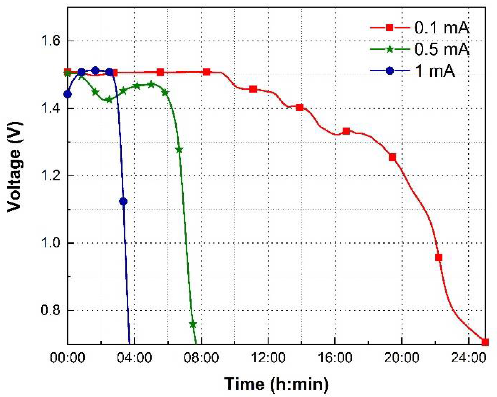
Figure 10.
Discharge characteristics of the flexible battery when flexed to different radii of curvature while discharging at 0.1 mA. (a) Discharge voltage versus time; and (b) discharge voltage versus capacity.
Figure 10.
Discharge characteristics of the flexible battery when flexed to different radii of curvature while discharging at 0.1 mA. (a) Discharge voltage versus time; and (b) discharge voltage versus capacity.


Table 1.
Illustration of battery capacities with reference to the active mass and the electrode area for different test cases.
Table 1.
Illustration of battery capacities with reference to the active mass and the electrode area for different test cases.
| Case | Discharge Current | Discharge Capacity | Specific Capacity | Areal Capacity |
|---|---|---|---|---|
| Without bending (Flat) | 0.1 | 2.5 | 86.21 | 0.78 |
| Bend radius of 1.25 cm | 0.1 | 1.75 | 60.34 | 0.55 |
| Bend radius of 0.8 cm | 0.1 | 1.6 | 55.17 | 0.50 |
Publisher’s Note: MDPI stays neutral with regard to jurisdictional claims in published maps and institutional affiliations. |
© 2022 by the authors. Licensee MDPI, Basel, Switzerland. This article is an open access article distributed under the terms and conditions of the Creative Commons Attribution (CC BY) license (https://creativecommons.org/licenses/by/4.0/).
Share and Cite
MDPI and ACS Style
Kota, A.; Kum, L.W.; Vallurupalli, K.; Gogia, A.; Neidhard-Doll, A.T.; Chodavarapu, V.P. Highly Flexible Stencil Printed Alkaline Ag2O-Zn Battery for Wearable Electronics. Batteries 2022, 8, 74. https://doi.org/10.3390/batteries8070074
AMA Style
Kota A, Kum LW, Vallurupalli K, Gogia A, Neidhard-Doll AT, Chodavarapu VP. Highly Flexible Stencil Printed Alkaline Ag2O-Zn Battery for Wearable Electronics. Batteries. 2022; 8(7):74. https://doi.org/10.3390/batteries8070074
Chicago/Turabian StyleKota, Akash, Lenin W. Kum, Kavya Vallurupalli, Ashish Gogia, Amy T. Neidhard-Doll, and Vamsy P. Chodavarapu. 2022. "Highly Flexible Stencil Printed Alkaline Ag2O-Zn Battery for Wearable Electronics" Batteries 8, no. 7: 74. https://doi.org/10.3390/batteries8070074
Note that from the first issue of 2016, this journal uses article numbers instead of page numbers. See further details here.