
A True Non-Newtonian Electrolyte for Rechargeable Hybrid Aqueous Battery
 , , ,
, , ,
Abstract
:1. Introduction
2. Experimental Section
2.1. Preparation of Batteries
2.2. Instrumentation
2.3. Electrochemical Measurements
3. Results and Discussion
4. Conclusions
Supplementary Materials
Author Contributions
Funding
Institutional Review Board Statement
Informed Consent Statement
Data Availability Statement
Conflicts of Interest
References
- Liu, H.; Wang, J.-G.; You, Z.; Wei, C.; Kang, F.Y.; Wei, B. Rechargeable aqueous zinc-ion batteries: Mechanism, design strategies and future perspectives. Mater. Today 2021, 42, 73–98. [Google Scholar] [CrossRef]
- Hollax, E. Advanced electrochemical energy sources for space power system—A review. J. Power Sources 1979, 4, 11–19. [Google Scholar] [CrossRef]
- Borchers, N.; Clark, S.; Horstmann, B.; Jayasayee, K.; Juel, M.; Stevens, P. Innovative zinc-based batteries. J. Power Sources 2021, 484, 229309. [Google Scholar] [CrossRef]
- Kordesh, K.; Weissenbacher, M. Rechargeable alkaline manganese dioxide/zinc batteries. J. Power Sources 1994, 51, 61–78. [Google Scholar] [CrossRef]
- Liu, Q.; Pan, Z.; Wang, E.; An, L.; Sun, G. Aqueous metal-air batteries: Fundamentals and applications. Energy Storage Mater. 2020, 27, 478–505. [Google Scholar] [CrossRef]
- Dubarry, M.; Qin, N.; Brooker, P. Calendar aging of commercial Li-ion cells of different chemistries—A review. Curr. Opin. Electrochem. 2018, 9, 106–133. [Google Scholar] [CrossRef]
- Gao, Y.; Zhang, X.; Cheng, Q.; Guo, B.; Yang, J. Classification and review of the charging strategies for commercial lithium-ion batteries. IEEE Access 2019, 7, 43511–43524. [Google Scholar] [CrossRef]
- Battistel, A.; Palagonia, M.S.; Brogioli, D.; la Mantia, F.; Trócoli, R. Electrochemical Methods for Lithium Recovery: A Comprehensive and Critical Review. Adv. Mater. 2020, 32, 1905440. [Google Scholar] [CrossRef] [Green Version]
- Perea, A.; Paolella, A.; Dubé, J.; Champagne, D.; Mauger, A.; Zaghib, K. State of charge influence on thermal reactions and abuse tests in commercial lithium-ion cells. J. Power Sources 2018, 399, 392–397. [Google Scholar] [CrossRef]
- Zhang, H.; Li, C.; Eshetu, G.G.; Laruelle, S.; Grugeon, S.; Zaghib, K.; Julien, C.; Mauger, A.; Guyomard, D.; Rojo, T.; et al. From Solid-Solution Electrodes and the Rocking-Chair Concept to Today’s Batteries. Angew. Chem. Int. Ed. 2020, 59, 534–538. [Google Scholar] [CrossRef]
- Chen, S.; Lan, R.; Humphreys, J.; Tao, S. Perchlorate Based “Oversaturated Gel Electrolyte” for an Aqueous Rechargeable Hybrid Zn–Li Battery. ACS Appl. Energy Mater. 2020, 3, 2526–2536. [Google Scholar] [CrossRef]
- Xu, Z.; Fan, Q.; Li, Y.; Wang, J.; Lund, P.D. Review of zinc dendrite formation in zinc bromine redox flow battery. Renew. Sustain. Energy Rev. 2020, 127, 109838. [Google Scholar] [CrossRef]
- Cai, Z.; Ou, Y.; Wang, J.; Xiao, R.; Fu, L.; Yuan, Z.; Zhan, R.; Sun, Y. Chemically resistant Cu–Zn/Zn composite anode for long cycling aqueous batteries. Energy Storage Mater. 2020, 27, 205–211. [Google Scholar] [CrossRef]
- Olbasa, B.W.; Fenta, F.W.; Chiu, S.-F.; Tsai, M.-C.; Huang, C.-J.; Jote, B.A.; Beyene, T.T.; Liao, Y.-F.; Wang, C.-H.; Su, W.-N.; et al. High-Rate and Long-Cycle Stability with a Dendrite-Free Zinc Anode in an Aqueous Zn-Ion Battery Using Concentrated Electrolytes. ACS Appl. Energy Mater. 2020, 3, 4499–4508. [Google Scholar] [CrossRef]
- Zampardi, G.; Compton, R.G. Fast electrodeposition of zinc onto single zinc nanoparticles. J. Solid State Electrochem. 2020, 24, 2695–2702. [Google Scholar] [CrossRef] [PubMed] [Green Version]
- Clark, S.; Borchers, N.; Jusys, Z.; Behm, R.J.; Horstmann, B. Aqueous Zinc Batteries. In Encyclopedia of Electrochemistry; John Wiley & Sons: Hoboken, NJ, USA, 2020; Available online: https://onlinelibrary.wiley.com/doi/10.1002/9783527610426.bard110022 (accessed on 12 July 2022).
- Hoang, T.K.A.; Doan, T.N.L.; Sun, K.E.K.; Chen, P. Corrosion chemistry and protection of zinc & zinc alloys by polymer-containing materials for potential use in rechargeable aqueous batteries. RSC Adv. 2015, 5, 41677–41691. [Google Scholar]
- Gaberšček, M.; Pejovnik, S. Impedance spectroscopy as a technique for studying the spontaneous passivation of metals in electrolytes. Electrochim. Acta 1996, 41, 1137–1142. [Google Scholar] [CrossRef]
- Shen, X.-W.; Li, Y.-T.; Qian, T.; Liu, J.; Zhou, J.-Q.; Yan, C.-L.; Goodenough, J.B. Lithium anode stable in air for low-cost fabrication of a dendrite-free lithium battery. Nat. Commun. 2019, 10, 900. [Google Scholar] [CrossRef] [Green Version]
- Lu, W.; Xie, C.; Zhang, H.; Li, X. Inhibition of Zinc Dendrite Growth in Zinc-Based Batteries. ChemSusChem 2018, 11, 3996–4006. [Google Scholar] [CrossRef]
- Mainar, A.R.; Colmenares, L.C.; Blazquez, J.A.; Urdampilleta, I. A brief overview of secondary zinc anode development: The key of improving zinc-based energy storage systems. Int. J. Energy Res. 2018, 42, 903–918. [Google Scholar] [CrossRef]
- Yadav, P.K.; Raghav, S.; Raghav, J.; Swarupa Tripathy, S.S. Electrolytes for Zn-Ion Batteries. In Zinc Batteries: Basics, Developments, and Application; Boddula, R., Inamuddin Asiri, A.M., Eds.; Scrivener Publishing & Wiley and Sons: Hoboken, NJ, USA, 2020; pp. 51–72. [Google Scholar]
- Beck, F.; Ruetschi, P. Rechargeable batteries with aqueous electrolytes. J. Power Sources 2000, 45, 2467–2482. [Google Scholar] [CrossRef]
- Lambert, D.W.H.; Greenwood, P.H.J.; Reed, M.C. Advances in gelled-electrolyte technology for valve-regulated lead-acid batteries. J. Power Sources 2002, 107, 173–179. [Google Scholar] [CrossRef]
- Hoang, T.K.A.; Doan, T.N.L.; Cho, J.H.; Su, J.Y.J.; Lee, C.; Lu, C.; Chen, P. Sustainable Gel Electrolyte Containing Pyrazole as Corrosion Inhibitor and Dendrite Suppressor for Aqueous Zn/LiMn2O4 Battery. Chemsuschem 2017, 10, 2816–2822. [Google Scholar] [CrossRef] [PubMed]
- Tantichanakul, T.; Chailapakul, O.; Tantavichet, N. Influence of Fumed Silica and Additives on the Gel Formation and Performance of Gel Valve-regulated Lead-acid Batteries. J. Ind. Eng. Chem. 2013, 19, 2085–2091. [Google Scholar] [CrossRef]
- Pan, K.; Shi, G.; Li, A.; Li, H.; Zhao, R.; Wang, F.; Zhang, W.; Chen, Q.; Chen, H.; Xiong, Z.; et al. The Performance of a Silica-based Mixed Gel Electrolyte in Lead Acid Batteries. J. Power Sources 2012, 209, 262–268. [Google Scholar] [CrossRef]
- Toniazzo, V. The key to success: Gelled-electrolyte and optimized separators for stationery lead-acid batteries. J. Power Sources 2006, 158, 1124–1132. [Google Scholar] [CrossRef]
- Losq, C.L.; Cody, G.D.; Mysen, B.O. Complex IR spectra of OH− groups in silicate glasses: Implications for the use of the 4500 cm−1 IR peak as a marker of OH− groups concentration. Am. Mineral. 2015, 100, 945–950. [Google Scholar] [CrossRef]
- Dingemans, G.; van Helvoirt, C.A.A.; Pierreux, D.; Keuning, W.; Kessels, W.M.M. Plasma-Assisted ALD for the Conformal Deposition of SiO2: Process, Material and Electronic Properties. J. Electrochem. Soc. 2012, 159, H277. [Google Scholar] [CrossRef] [Green Version]
- Bertoluzza, A.; Fagnano, C.; Morrelli, M.A.; Gottardi, V.; Guglielmi, M. Raman and infrared spectra on silica gel evolving toward glass. J. Non-Cryst. Solids 1982, 48, 117–128. [Google Scholar] [CrossRef]
- User Manual of Seabird Nickel Metal Hydride Battery. Available online: https://web.archive.org/web/20090227062546/http://www.seabird.com/pdf_documents/manuals/NiMH_002.pdf (accessed on 7 May 2019).
- Catherino, H.A.; Shi, P.; Rusek, A.; Feres, F. Self-Discharging of Lead-Acid Batteries. SAE Tech. Pap. Ser. 2000, 1, 0305. [Google Scholar]
- Cui, J.; Wu, X.; Yang, S.; Li, C.; Tang, F.; Chen, J.; Chen, Y.; Xiang, Y.; Wu, X.; He, Z. Cryptomelane-Type KMn8O16 as Potential Cathode Material—For Aqueous Zinc Ion Battery. Front. Chem. 2018, 6, 352. [Google Scholar] [CrossRef] [PubMed]
- Suo, L.; Borodin, O.; Sun, W.; Fan, X.; Yang, C.; Wang, F.; Gao, T.; Ma, Z.; Schroeder, M.; von Cresce, A.; et al. Advanced High-Voltage Aqueous Lithium-Ion Battery Enabled by “Water-in-Bisalt” Electrolyte. Angew. Chem. Int. Ed. 2016, 55, 7136–7141. [Google Scholar] [CrossRef] [PubMed]
- Zhu, Y.S.; Wang, X.J.; Hou, Y.Y.; Gao, X.W.; Liu, L.L.; Wu, Y.P.; Shimizu, M. A new single-ion polymer electrolyte based on polyvinyl alcohol for lithium ion batteries. Electrochim. Acta 2013, 87, 113–118. [Google Scholar] [CrossRef]
- Amaral, F.A.; Dalmolin, C.; Canobre, S.C.; Bocchihttps, N.; Rocha-Filho, R.C.; Biaggio, S.R. Electrochemical and physical properties of poly(acrylonitrile)/poly(vinyl acetate)-based gel electrolytes for lithium ion batteries. J. Power Sources 2007, 164, 379–385. [Google Scholar] [CrossRef]
- Wang, G.; Lu, X.; Ling, Y.; Zhai, T.; Wang, H.; Tong, Y.; Li, Y. LiCl/PVA gel electrolyte stabilizes vanadium oxide nanowire electrodes for pseudocapacitors. ACS Nano 2012, 6, 10296–10302. [Google Scholar] [CrossRef]
- Zhang, X.; Wang, L.; Peng, J.; Cao, P.; Cai, X.; Li, J.; Zhai, M. A Flexible Ionic Liquid Gelled PVA-Li2SO4 Polymer Electrolyte for Semi-Solid-State Supercapacitors. Adv. Mater. Interfaces 2015, 12, 1500267. [Google Scholar] [CrossRef]

| Gel Types | 5% FS | 4% FS + 1% PVA | 3% FS + 2% PVA |
|---|---|---|---|
| Ball penetration depth (mm) | 7.3 | 7.5 | 8.1 |
| Conductivity of electrolyte (mS⋅cm−1) * | 60.10 ± 0.10 | 59.93 ± 0.25 | 61.46 ± 0.21 |
| 1st gelling time | 4 h | 6 h | 11 h |
| 2nd gelling time (after disturbance) | 1.5 h | 2.2 h | 3.1 h |
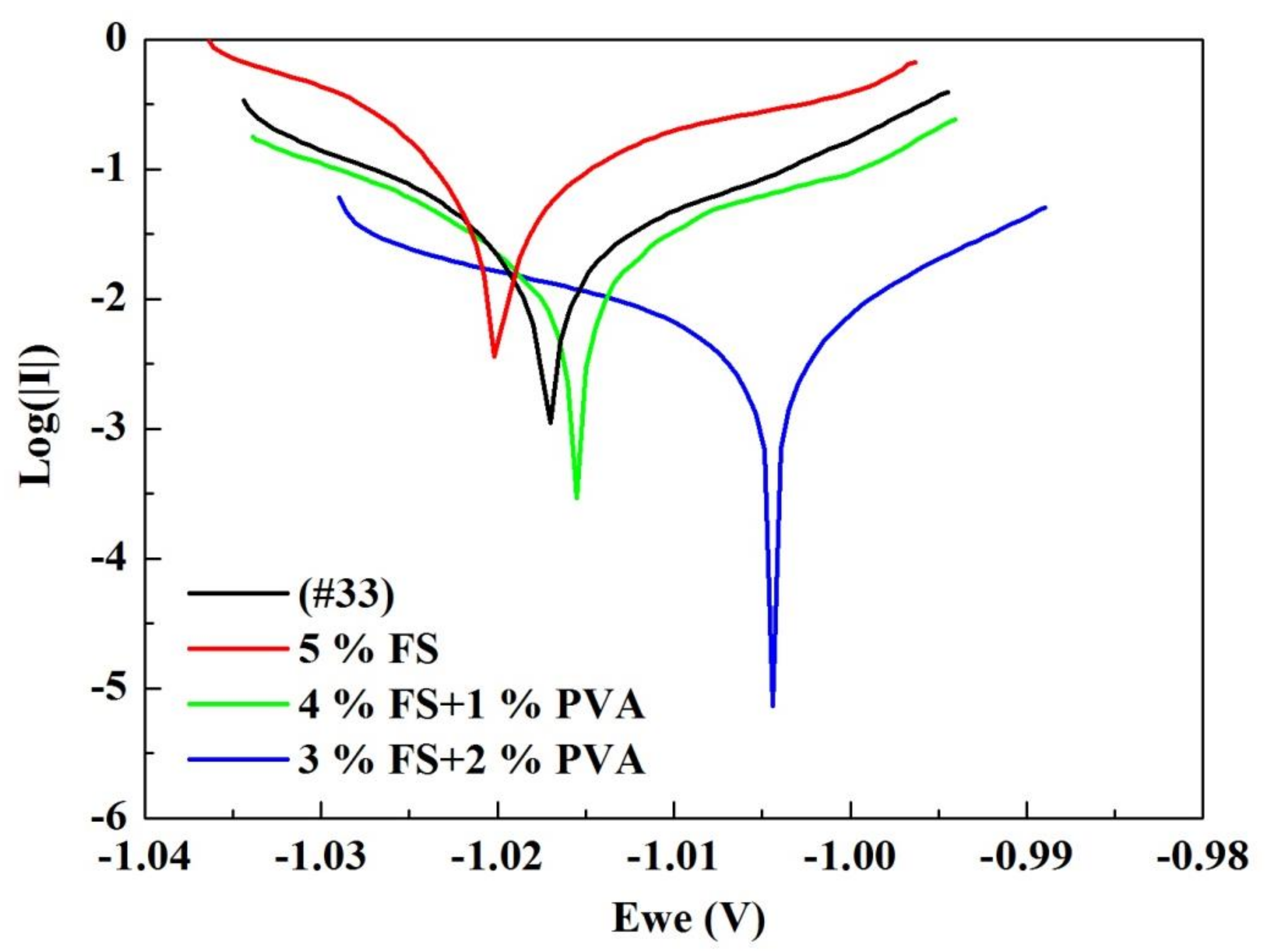
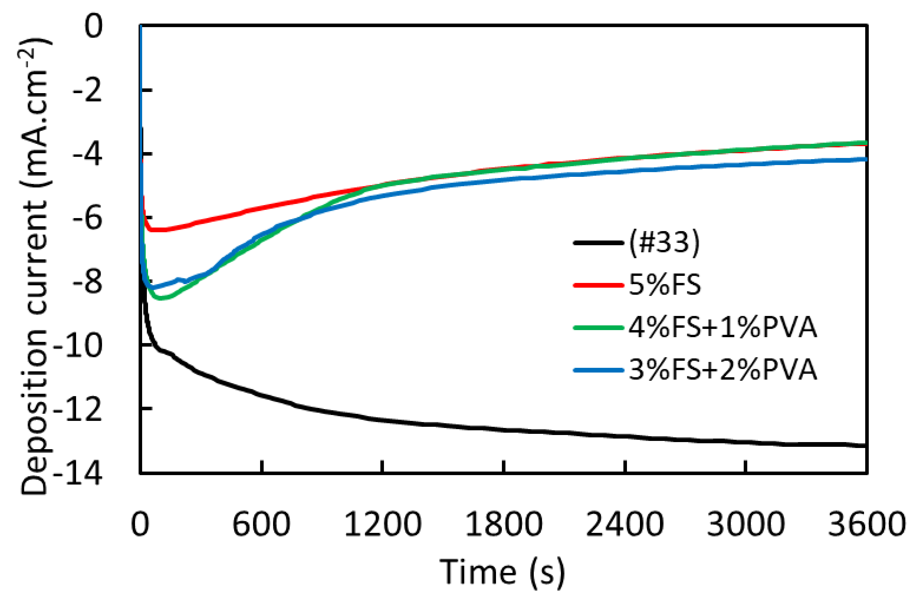
| Type of Electrolyte | Corrosion Potential (mV) | Corrosion Current Density (μA⋅cm−2) | Chronoamperometry Current Density (mA⋅cm−2) |
|---|---|---|---|
| (#33) | −1016.32 ± 1.07 | 5.25 ± 0.57 | −13.1438 |
| 5% FS | −1019.93 ± 0.10 | 19.73 ± 2.34 | −3.6809 |
| 4% FS + 1% PVA | −1015.87 ± 0.46 | 5.7922 ± 1.13 | −3.6542 |
| 3% FS + 2% PVA | −1003.84 ± 0.24 | 1.4096 ± 0.82 | −4.1765 |
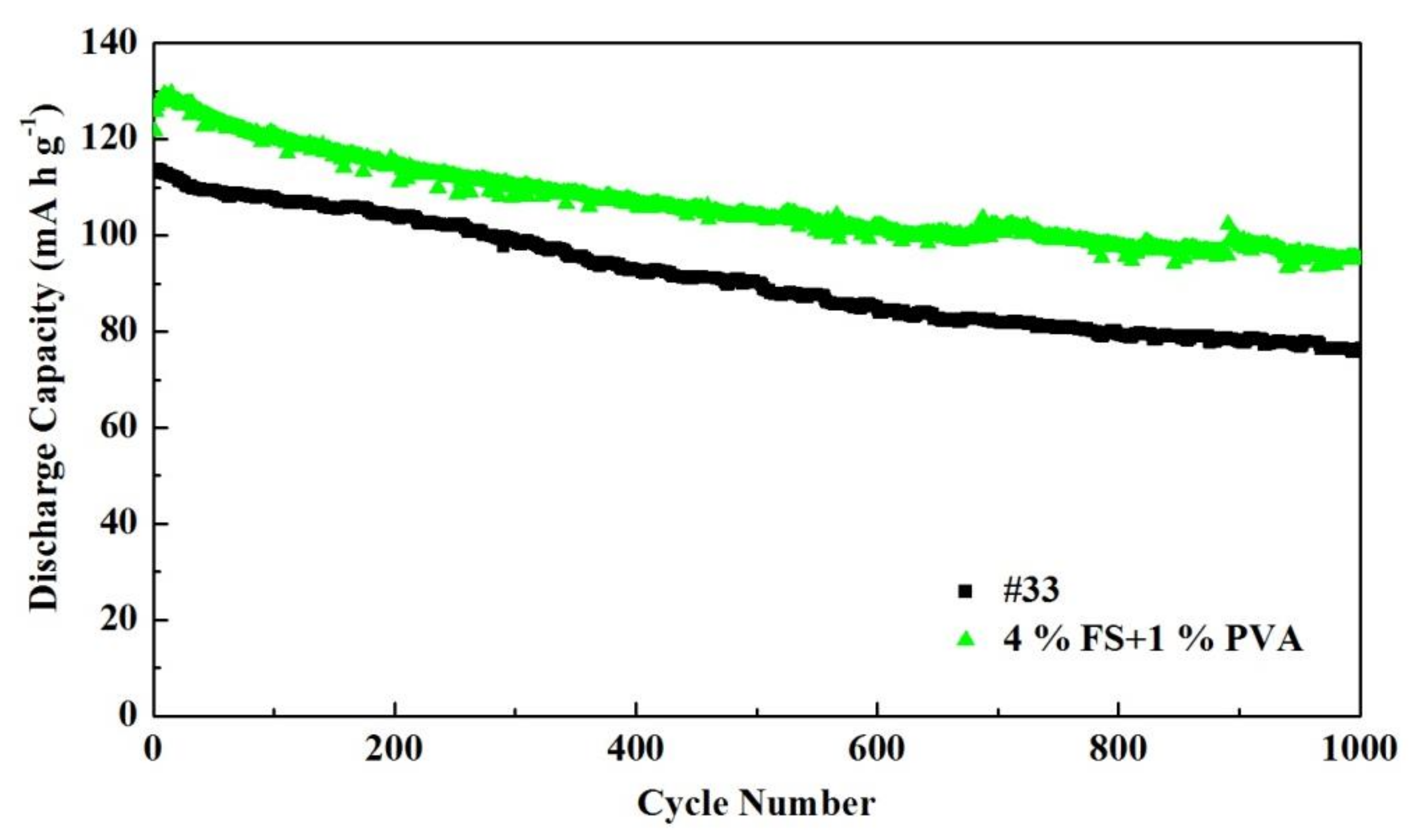
| Battery | 1st Discharge 0.2 C | 1st Discharge 4 C | 1st Discharge 0.2 C a | Float Current b | Open Circuit Voltage c |
|---|---|---|---|---|---|
| The conventional | 120.02 ± 3.83 | 95.59 ± 7.01 | 118.48 ± 5.08 | 0.008 ± 0.001 | 1.947 ± 0.014 |
| 5% FS | 121.14 ± 2.99 | 97.54 ± 1.98 | 119.72 ± 1.91 | 0.0067 ± 0.00058 | 1.970 ± 0.005 |
| 4% FS + 1% PVA | 134.25 ± 4.41 | 109.63 ± 7.20 | 129.96 ± 4.79 | 0.01 ± 0.0014 | 1.956 ± 0.009 |
| 3% FS + 2% PVA | 133.67 ± 7.13 | 106.97 ± 9.04 | 128.45 ± 4.87 | 0.01067 ± 0.0015 | 1.968 ± 0.012 |
Publisher’s Note: MDPI stays neutral with regard to jurisdictional claims in published maps and institutional affiliations. |
© 2022 by the authors. Licensee MDPI, Basel, Switzerland. This article is an open access article distributed under the terms and conditions of the Creative Commons Attribution (CC BY) license (https://creativecommons.org/licenses/by/4.0/).
Share and Cite
Hoang, T.K.A.; Li, L.; Zhi, J.; Doan, T.N.L.; Dong, W.; Huang, X.; Ma, J.; Xie, Y.; Chang, M.; Chen, P. A True Non-Newtonian Electrolyte for Rechargeable Hybrid Aqueous Battery. Batteries 2022, 8, 71. https://doi.org/10.3390/batteries8070071
Hoang TKA, Li L, Zhi J, Doan TNL, Dong W, Huang X, Ma J, Xie Y, Chang M, Chen P. A True Non-Newtonian Electrolyte for Rechargeable Hybrid Aqueous Battery. Batteries. 2022; 8(7):71. https://doi.org/10.3390/batteries8070071
Chicago/Turabian StyleHoang, Tuan K. A., Longyan Li, Jian Zhi, The Nam Long Doan, Wenhan Dong, Xiaoxiao Huang, Junhong Ma, Yahong Xie, Menglei Chang, and P. Chen. 2022. "A True Non-Newtonian Electrolyte for Rechargeable Hybrid Aqueous Battery" Batteries 8, no. 7: 71. https://doi.org/10.3390/batteries8070071