
Effect of Mechanical Activation and Carbon Coating on Electrochemistry of TiNb2O7 Anodes for Lithium-Ion Batteries


1
Institute of Solid State Chemistry and Mechanochemistry, Siberian Branch of Russian Academy of Sciences, 18 Kutateladze, 630128 Novosibirsk, Russia
2
Department of Natural Sciences, Novosibirsk State University, 2 Pirogova, 630090 Novosibirsk, Russia
*
Author to whom correspondence should be addressed.
Batteries 2022, 8(6), 52; https://doi.org/10.3390/batteries8060052
Submission received: 11 May 2022
/
Revised: 25 May 2022
/
Accepted: 31 May 2022
/
Published: 1 June 2022
(This article belongs to the Special Issue Anode and Cathode Materials for Lithium-Ion and Sodium-Ion Batteries)
Abstract
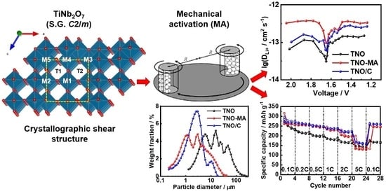
:TiNb2O7 anode material with a Wadsley–Roth crystallographic shear structure was prepared by solid-state synthesis at a relatively low temperature (1000 °C) and a short calcination time (4 h) using preliminary mechanical activation of the reagent mixture. The as-prepared final product was then ball milled in a planetary mill with and without carbon black. The crystal structure and morphology of the samples were studied by X-ray diffraction (XRD) and scanning electron microscopy (SEM). Electrochemical performance was studied in a galvanostatic mode in varied voltage intervals and at different cycling rates in combination with in situ electrochemical impedance spectroscopy (EIS) measurements. The resistance measured using in situ EIS had the highest values at the end of the discharge and the lowest when charging. The lithium diffusion coefficient, determined by galvanostatic intermittent titration technique (GITT), in samples milled with and without carbon black was an order of magnitude higher than that for the pristine sample. It was shown that improved electrochemical performance of the carbon composite TiNb2O7/C (reversible capacity of 250 mAh g−1 at C/10 with Coulomb efficiency of ~99%) was associated with improved conductivity due to the formation of a conductive carbon matrix and uniform distribution of submicron particles by size.
1. Introduction
Most commercial lithium-ion batteries (LIBs) use graphite as an intercalating anode with a theoretical capacity of 372 mAh g−1. The intercalation potential of Li into graphite is between 0 and 0.25 V vs. Li+/Li. This falls below the electrochemical stability window of the electrolyte during charging, which leads to its decomposition at the graphite surface, forming the passivating solid electrolyte interphase (SEI) [1,2]. Moreover, graphite anodes do not meet the requirements for high-power LIBs because of sluggish Li-ion diffusion and insufficient electrochemical kinetics. To avoid the formation of SEI and to improve kinetics, a series of high-voltage oxide anode materials has been developed [3]. The most promising among them is lithium titanium spinel Li4Ti5O12, which is a ‘zero strain’ anode material. It has an operating voltage of 1.55 V vs. Li+/Li, which avoids the SEI formation [4]. The disadvantage of Li4Ti5O12 is its low theoretical specific capacity (175 mAh g−1) and the need to be prepared at nanoscale for practical application [4].
Recently, Nb-based oxides with Wadsley–Roth crystallographic shear structures have been intensively studied as high-rate anode materials with increased specific capacity for LIBs [5,6,7,8,9]. Their unique stable shear ReO3-type crystal structure and the possibility of implementing multielectron redox processes give hope for the development of next-generation of LIBs characterized by high energy density and long cycle life [9]. Li-ion insertion into Nb-based oxides mainly occurs at a voltage above 1 V vs. Li+/Li; therefore, SEI is not formed [9]. The theoretical volumetric capacities of Wadsley–Roth phases are above 1679 mAh cm−3, while that of Li4Ti5O12 is 609.3 mAh cm−3 [7]. Therefore, such anode materials can provide great advantages over the conventional graphite and Li4Ti5O12 anodes in terms of specific energy, rate capability, and safety and should be promising candidates for the role of the anode for high-power LIBs.
TiNb2O7 is the most titanium-rich member of the TiO2–Nb2O5 system [10,11]. It was first proposed as an anode material by Goodenough et al. in 2011 to replace Li4Ti5O12 [12]. The theoretical capacity of TiNb2O7 is 387.6 mAh g−1, arising from the operation of several redox couples (Ti4+/Ti3+, Nb5+/Nb4+, Nb4+/Nb3+) for a five-electron transfer, which is more than twice of that of Li4Ti5O12 and is comparable with that of graphite [12]. Its average insertion voltage is about 1.64 V vs. Li+/Li at 0.1 C, which is close to that of 1.55 V for Li4Ti5O12. However, pure TiNb2O7 has the same drawbacks as Li4Ti5O12: it is an oxide with a wide band gap and therefore has poor electronic conductivity (10−9–10−11 S cm−1), which can be increased by the introduction of oxygen vacancies, doping, and conductive coating [5,8,9].
Li diffusion in the crystal structure of TiNb2O7 is anisotropic. As shown in [13], lithium is capable of rapidly migrating through T1 and T2 tunnels along the b axis within the (3 × 3)∞ block (Figure 1), which determines the high-rate capability of TiNb2O7. In addition, cross-tunnel diffusion is possible within the block, but diffusion between blocks is negligible [13].
TiNb2O7 can be obtained in various ways. Solution methods, such as hydrothermal and sol–gel, allow one to adjust the morphology and particle size and obtain nanosized TiNb2O7 with a uniform particle size distribution [8]. However, these methods typically use expensive organic reagents, which limit their application in industry. Usually, cost-effective and simple solid-state synthesis is used as the most suitable way to produce TiNb2O7. However, this method requires heat treatment of a reagent mixture of TiO2 and Nb2O5 at a high temperature of 1000–1400 °C for 12–24 h and usually results in the formation of a heterogeneous product with micron-sized agglomerated particles and wide particle size distribution [5,8]. There have been several reports in which the authors tried to reduce the temperature and synthesis time. Baek et al. [14] reported a fast synthesis method for TiNb2O7 that required 7 min of heating in the microwave. Although microwave synthesis is fast, simple, and inexpensive, its scalability is questionable. The combination of solid-state synthesis with preliminary mechanical activation (MA) is a promising way to prepare highly homogeneous materials by reducing the temperature and duration of the process. Adhami et al. [15] synthesized TiNb2O7 using MA for 5 h and postannealing at 900 °C for 2 h. Oliveira et al. [16] reduced the synthesis time to 2 min but used long-term operations to prepare the precursor, including ball milling for 24 h.
In the present work, TiNb2O7 (hereafter TNO) was prepared by solid-state synthesis using preliminary MA of the reagent mixture for 5 min and subsequent heating at 1000 °C for 4 h. The micrometer-sized single-phase final product was then ball milled in a planetary mill with and without carbon black (hereafter TNO/C and TNO-MA, respectively). The electrochemical performance of the as-prepared samples was studied.
2. Results and Discussion
2.1. Crystal Structure, Particle Size, and Morphology
The crystal structure of TNO is built from (3 × 3)∞ blocks or columns of ReO3 type, infinite along the b axis and bounded by crystallographic shear planes [17,18]. It consists of TiO6 and NbO6 octahedra sharing corners within the blocks and edges between the blocks (Figure 1). According to [13], lithium migrates through tunnels between MO6 (M = Nb, Ti) octahedra in the ReO3 block, hopping between positions with a tetrahedral (LiO4) and a pyramidal (LiO5) environment; diffusion through the crystallographic shear planes is disrupted. The authors [13] showed that the activation energies of lithium migration down the tunnels are small (100−200 meV), while for lithium migration across the block, the activation energies are noticeably higher (700−1000 meV). At a high Li content in TiNb2O7, ionic motion is hindered. On the other hand, during lithium intercalation, effective n-type self-doping occurs, causing high-rate conductivity. The structure undergoes a transition from partially localized to delocalized electronic behavior as the concentration of lithium increases [13].
Rietveld-refined XRD patterns of the as-prepared TNO, TNO-MA, and TNO/C samples are shown in Figure 2. The samples were well-crystalline and single-phase materials. All reflections were successfully indexed based on the monoclinic structure with the C2/m space group (PDF #77-1374) [19]. After MA, the broadening of reflections increased, which indicated a decrease in coherent scattering regions. Average crystallite sizes were equal to 161.1(19) nm for TNO, 74(1) nm for TNO-MA and 99(2) nm for TNO/C. The refined lattice parameters of the samples and the Rietveld discrepancy values, Rwp and GOF, are shown in Table 1. Lattice parameters slightly increased after MA and carbon coating, which was attributed to a slight structural disordering or partial reduction of Ti4+ or Nb5+ ions.
Microstructural analysis of the as-prepared TNO, TNO-MA, and TNO/C samples was carried out by SEM (Figure 3). The particles of TNO had an irregular morphology with a submicron particle size, as is typical for mechanochemically prepared materials. It was possible to distinguish small primary particles of about 500 nm in size, along with larger micron-sized agglomerates of smaller primary particles. The particle sizes of TNO-MA and TNO/C were noticeably smaller than those of pristine TNO and were equal to about 350 nm. Figure 4 shows the particle size distribution for these three samples as measured by a particle size analyzer. Several maxima ranging from 5 to 50 μm were observed on the histogram of TNO with D50 = 12.4 μm. After MA, the particle size decreased to 1–10 μm with D50 = 2.13 μm. For the carbon composite TNO/C, the narrowest particle size distribution was observed with D50 = 2.22 μm. Thus, the short-time MA of TNO with or without carbon black significantly reduced the particle size. The addition of carbon black contributed to a more uniform particle size distribution, which agreed well with the SEM results.
2.2. Electrochemical Performance of TNO Samples
In order to choose an appropriate voltage interval for cycling of all TNO samples, we first investigated the electrochemical performance of pristine TNO in different voltage ranges from 3 to 1 V and then reducing the low cutoff by 0.1 V with each cycle (Figure 5). The initial charge–discharge specific capacity, when cycled to 1 V, was 296/267 mAh g−1. When the low cutoff decreased to 0.8 V, the specific discharge and charge capacities slightly increased. When the low cutoff decreased to below 0.8 V, the capacity decreased, most probably because of side reactions of the electrode with the electrolyte. This was accompanied by a notable increase in resistance, registered by in situ EIS in the frequency range of 10 kHz–100 mHz (Figure 5b). The reduced capacity was maintained even after returning to the 1 V cutoff (see value of capacity after red dashed line in Figure 5a).
In the further experiments, the as-prepared TNO, TNO-MA, and TNO/C samples were cycled in the 1.0–3.0 V range at C/10–5C cycling rates. Figure 6 shows charge–discharge profiles of the samples and the corresponding dQ/dV vs. voltage plots. The charge–discharge profiles have three regions: namely, a sloping shape from 3.0 to 1.6 V (corresponding to insertion of ~1 Li) followed by a small plateau at 1.6 V (1–2 Li) and then a sloping curve from 1.6 to 1.0 V (>2 Li). This indicates a change in the Li intercalation mechanism from single-phase to two-phase and back to single-phase [20,21]. The process is accompanied by simultaneous reduction of both titanium and niobium during discharge due to the overlap of their d-bands [13,22]. According to [23], the two overlapping redox couples observed on the differential curves at 1.75–1.81 V and 1.61–1.66 V were attributed to Ti4+/Ti3+ and Nb5+/Nb4+, while the couple of less-intensive peaks at 1.32–1.34 V corresponded to Nb4+/Nb3+.
Figure 7 shows the charge–discharge specific capacity of TNO, TNO-MA, and TNO/C vs. cycling number and cycling rate. The initial discharge capacities at a C/10 rate were equal to 310 mAh g−1 for TNO, 322 mAh g−1 for TNO-MA, and 309 mAh g−1 for TNO/C, which were close to the theoretical capacity (387.7 mAh g−1). The initial charge capacities were 276, 267, and 270 mAh g−1 for TNO, TNO-MA, and TNO/C, respectively. Therefore, the irreversible capacities were equal to 34 mAh g−1 (11%), 55 mAh g−1 (17%), and 39 mAh g−1 (13%) for TNO, TNO-MA, and TNO/C, respectively, probably arising from the formation of a solid electrolyte interface (SEI). According to [24], a thin SEI layer was formed during the first discharge, although the operating voltage is higher than 1.0 V. Meanwhile, it was partially dissolved during the first charge in the voltage range of 1.0–3.0 V. After 50 cycles, the reversible capacity stabilized at 140 mAh g−1 for TNO, at 224 mAh g−1 for TNO-MA, and at 225 mAh g−1 for TNO/C, with Coulomb efficiency of ~99%. When the cycling rate increased from C/10 to 5C, the highest capacity (168 mAh g−1) was observed for TNO/C as a result of decreased particle size, uniform particle size distribution, and increased electronic conductivity due to formation of a conductive carbon matrix.
2.3. Changes in Ionic and Electronic Conductivity during Charge and Discharge
The impedance spectrum of the TNO/C sample showed a frequency-independent character, indicating that it had electronic conductivity with a high value of 8.67 × 10⁻³ S·cm−1. On the other hand, the curves for TNO and TNO-MA had a sloping form. Approximating their intersections with the x axis allowed obtaining values of conductivity equal to 4.32 × 10⁻¹¹ S·cm−1 for TNO and 4.10 × 10⁻¹¹ S·cm−1 for TNO-MA (Figure 8).
Interestingly, pristine carbon-free TNO mixed only with the binder with a ratio of TNO/PVDF = 95:5 intercalates Li ions during the first discharge at C/10 cycling rate (Figure 9a). The initial discharge capacity was equal to 210.37 mAh g−1. Note that TNO showed a clear insulating character with a wide band gap of ~3 eV [22,25]. The conduction band was contributed by d states of Nb and Ti atoms. The valence band was mostly contributed by p states of oxygen atoms [22]. During lithium intercalation, electrons from ionized Li ions partially occupied the conduction band of TNO, which led to a significant increase in the Fermi level of the system and metallic electronic conduction as a consequence [13,22,25]. The authors of [13], using magnetic measurements, showed that the electronic conductivity of TNO increased by seven orders of magnitude upon lithiation (n-type doping) and indicated that electrons exhibited both localized and delocalized character near the composition of Li0.60TiNb2O7. They established that the proportion of localized electrons was the largest at low lithium content, while at high lithium content, most electrons were delocalized. It is obvious that n-doping of the insulating d0-TNO by electrochemical reduction increased the concentration of carriers to turn it into an effective conductor. The discharge capacity was 210 mAh g−1, which was close to the discharge capacity of TNO with a conductive additive. However, the charge capacity of carbon-free TNO was only 32.5 mAh g−1. Figure 9b shows in situ EIS spectra of the pristine and carbon-free TNO after its discharge and charge. The resistance of carbon-free TNO after discharge became much smaller than that of pristine material; however, it significantly increased on charge. A similar phenomenon was described in [25]. The authors assumed that upon the initial discharge, a thin layer of electronically conductive phase LixTiNb2O7 was formed, while when charged, a nonconductive delithiated phase was generated on the surface of the TNO particles, which prevented the deintercalation of Li ions.
Based on the analysis of the crystal structure of TNO, where metal−metal interatomic distances through edge-shared octahedra along the shear planes (3.2–3.4 Å) were shorter than those for the ac planar cross-block metal−metal pathways (≥3.8 Å), the authors of [13] suggested that long-range electronic conductivity in TNO was directed down the b axis as well as long-range ionic conduction. The authors of [13] believed that ionic and electronic conductivity in TNO was strongly anisotropic because of the crystallographic shear planes, which prevented the transfer in the ac plane. Hence, TNO can be approximated as one-dimensional in the direction along the tunnel (b axis). Lithium diffusion decreased rapidly at higher Li content in TiNb2O7 [13]. Nevertheless, high-rate (de)lithiation of the bulk structure is determined by the facile hopping between parallel tunnels within ReO3 block, which makes 1D diffusion in TiNb2O7 different from that of LiFePO4 [13].
In situ EIS spectra were recorded for TNO at different states of charge and discharge. Figure 10 shows charge–discharge profiles for the first two cycles and how the impedance spectra changed at different voltages (marked with colored dots on the cycling curves). At the first discharge, the resistance increased from 308 Ω at the initial state to 369 Ω at 1.55 V. Next, it decreased to 282 Ω at 1.00 V. Upon the first charge, an extra semicircle appeared in the middle frequency range at voltages below 1.85 V, which most probably corresponded to the charge transfer. The resistance decreased until the end of the charge from 282 Ω at 1.00 V to 36 Ω at 3.00 V. At the second discharge, it increased slightly from 36 Ω at 3.00 V to 57 Ω at 1.55 V and then increased sharply to 270 Ω at the end of discharge. The changes upon the second charge were similar to those upon the first one: the resistance decreased from 270 Ω to 58 Ω. In Figure 10b,c, two equivalent circuits are present. The first describes the impedance spectra of TNO before cycling, while the second describes the impedance spectra of TNO upon the first charge at 1.85 V. R1 corresponds to the electrolyte resistance. The high-frequency semicircle is a parallel connection of the constant phase element CPE1 and resistance R2, which was attributed to the surface film formed on the anode [26,27]. The parallel connection of CPE2 and R3 describes a middle-frequency semicircle corresponding to charge transfer. In the low-frequency region, a straight line corresponds to the Warburg diffusion impedance W. Similar results for the second cycle were obtained by other authors [26,27,28,29]. The authors of [13] showed that lithium mobility was hindered at high Li content (i.e., at x > 3 in LixTiNb2O7) because of a transition from interstitial-mediated diffusion to vacancy-mediated diffusion.
Figure 11 shows the GITT and OCV curves and the calculated Li+ diffusion coefficient DLi+ as a function of the cell voltage during charge and discharge of TNO, TNO-MA, and TNO/C at room temperature. The average value of DLi+ for discharge/charge of TNO was 7.26 × 10⁻¹⁴/9.07 × 10−14 cm2 s−1. The average values of DLi+ for TNO-MA and TNO/C were greater than that for TNO and were equal to 1.84 × 10⁻¹³/2.56 × 10−13 cm2 s−1 and 1.41 × 10⁻¹³/1.52 × 10−13 cm2 s−1, respectively. For all the samples, DLi+ curves had a minimum corresponding to the plateau at 1.6 V characteristic of a two-phase Li+ intercalation mechanism, where the interface between two coexisting phases worsens the conditions for Li+ diffusion. This was comparable to data from the literature [13,30,31,32,33]. GITT measurements revealed that the values of DLi+ in TNO-MA and TNO-C were one order of magnitude higher than that in TNO and confirmed that the chemical diffusion coefficient of Li+ during the delithiation was higher than that during lithiation at high lithium concentration.
3. Materials and Methods
TiNb2O7 was prepared by solid-state synthesis using preliminary mechanical activation. Stoichiometric amounts of TiO2 anatase (Sigma Aldrich, St. Louis, MO, USA, 99.8%) and Nb2O5 (Reachim, Russia, 99.9%) were mechanically activated using a high-energy AGO-2 planetary mill with stainless steel jars and balls at 900 rpm for 5 min. The ball-to-powder ratio was 40:1. The activated reagent mixture was pressed into pellets and then annealed at 1000 °C for 4 h in air. One part of the as-prepared TNO was ball milled at 450 rpm for 3 min (hereafter TNO-MA). Another part of the TNO was ball milled with carbon black “P277” (from the Center for New Chemical Technologies SB RAS, Omsk, Russia) in a ratio of 95:5 under the same conditions to prepare a carbon composite TiNb2O7/C (hereafter TNO/C).
X-ray powder diffraction (XRD) patterns of the as-prepared samples were recorded within the 2θ range of 5–80° with a 0.02° step and an exposure time of 0.2 s in one point using a Bruker D8 Advance diffractometer with a high-rate LYNXEYE detector (Cu Kα radiation (λ = 1.54181 Å)). The lattice parameters were refined by the Rietveld method using the GSAS software package. The morphology of the samples was studied by scanning electron microscopy (SEM) using a Hitachi TM-1000 scanning electron microscope. The particle size distribution of the samples was measured using a MicroSizer 201 laser particle size analyzer.
For electrochemical testing, the composite cathodes were fabricated by mixing the active material with carbon black and PVDF/NMP binder in a ratio of 75:20:5. The mixed slurry was then casted on a copper foil using a doctor blade to obtain working electrodes. The working electrodes were dried in a vacuum oven at 90 °C for 2 h. The loading density of the active material was 2–3 mg cm−2; the electrode diameter was 10 mm. The Swagelok-type cells were assembled in an argon-filled glove box (VBOX-SS 950, Vilitek, Moscow, Russia) with Li as an anode, 1 M LiPF6 (Sigma Aldrich, 99.99%) solution in ethylene carbonate and dimethyl carbonate (Alfa Aesar, Haverhill, MA, USA, 99%) 1:1 by weight as an electrolyte, and a glass fiber filter (Whatman, Maidstone, UK, Grade GF/C) as a separator. The electrochemical performance of the samples was tested using a Biologic BCS 805 battery cycling system in a galvanostatic mode at C/10–5C charge–discharge rates within the voltage range of 1.0–3.0 V vs. Li+/Li at room temperature. Galvanostatic intermittent titration technique (GITT) measurements were carried out at a C/10 rate by applying a galvanostatic step for an interval of 20 min and a relaxation time of 40 min. The electrochemical impedance spectra (EIS) were measured in electrochemical cells during cycling at different states of charge–discharge in the frequency range 50 Hz–1 MHz at room temperature. The conductivity of the as-prepared samples was measured in pellets with Ag electrodes using a RLC meter E7-25 (Belarus) within the 50 Hz–1 MHz range at room temperature.
4. Conclusions
It was shown that when using preliminary mechanical activation, TiNb2O7 anode material with a Wadsley–Roth crystallographic shear structure could be successfully prepared by solid-state synthesis at a temperature of 1000 °C and within a short calcination time (4 h), both of which were lower than are usually used in conventional ceramic synthesis (~1200 °C and ~20 h, respectively). Ball milling of the final product with and without carbon black led to a decrease in particle size and a narrowing of granulometric composition. In situ EIS measurements revealed that the resistance varied from the highest at the end of discharge to the lowest when charging. It also increased with a decrease in low cutoff to 0.1 V because of the interaction of TNO with the electrolyte and the formation of SEI. The lithium diffusion coefficients determined by GITT in the milled samples were an order of magnitude higher than that for the pristine sample. It was shown that the enhanced electrochemical performance of the carbon composite TiNb2O7/C (reversible capacity of 250 mAh g−1 at C/10 with Coulomb efficiency of ~99%) was associated with improved conductivity due to the formation of the conductive carbon matrix and uniform distribution of submicron particles by size.
Author Contributions
N.V.K., conceptualization, methodology, writing—review and editing, supervision; D.Z.T., investigation, writing—original draft preparation. All authors have read and agreed to the published version of the manuscript.
Funding
The authors thank the Ministry of Science and Higher Education of the Russian Federation within the governmental order for the Institute of Solid State Chemistry and Mechanochemistry SB RAS (project FWUS-21-0006) for partial support of this work.
Institutional Review Board Statement
Not applicable.
Informed Consent Statement
Not applicable.
Acknowledgments
The authors are thankful to A.V. Ukhina for registering XRD patterns and to A.A. Matvienko from ISSCM SB RAS for obtaining SEM images.
Conflicts of Interest
The authors declare no conflict of interest.
References
- Goriparti, S.; Miele, E.; De Angelis, F.; Di Fabrizio, E.; Zaccaria, R.P.; Capiglia, C. Review on recent progress of nanostructured anode materials for Li-ion batteries. J. Power Sources 2014, 257, 421–443. [Google Scholar] [CrossRef]
- An, S.J.; Li, J.; Daniel, C.; Mohanty, D.; Nagpure, S.; Wood III, D.L. The state of understanding of the lithium-ion-battery graphite solid electrolyte interphase (SEI) and its relationship to formation cycling. Carbon 2016, 105, 52–76. [Google Scholar] [CrossRef]
- Zhou, C.-A.; Yao, Z.J.; Xia, X.H.; Wang, X.L.; Gu, C.D.; Tu, J.P. Low-strain titanium-based oxide electrodes for electrochemical energy storage devices: Design, modification and application. Mater. Today Nano 2020, 11, 100085. [Google Scholar] [CrossRef]
- Chen, Z.; Li, H.; Wu, L.; Lu, X.; Zhang, X. Li4Ti5O12 Anode: Structural Design from Material to Electrode and the Construction of Energy Storage Devices. Chem. Rec. 2018, 18, 350–380. [Google Scholar] [CrossRef] [PubMed]
- Zhao, Z.; Xue, Z.; Xiong, Q.; Zhang, Y.; Hu, X.; Chi, H.; Qin, H.; Yuan, Y.; Ni, H. Titanium niobium oxides (TiNb2O7): Design, fabrication and application in energy storage devices. Sustain. Mater. Technol. 2021, 30, e00357. [Google Scholar] [CrossRef]
- Aghamohammadi, H.; Hassanzadeh, N.; Eslami-Farsani, R. A review study on titanium niobium oxide-based composite anodes for Li-ion batteries: Synthesis, structure, and performance. Ceram. Int. 2021, 47, 26598–26619. [Google Scholar] [CrossRef]
- Griffith, K.J.; Harada, Y.; Egusa, S.; Ribas, R.M.; Monteiro, R.S.; Von Dreele, R.B.; Cheetham, A.K.; Cava, R.J.; Grey, C.P.; Goodenough, J.B. Titanium Niobium Oxide: From Discovery to Application in Fast-Charging Lithium Ion Batteries. Chem. Mater. 2021, 33, 4–18. [Google Scholar] [CrossRef]
- Wang, H.; Qian, R.; Cheng, Y.; Wu, H.-H.; Wu, X.; Pan, K.; Zhang, Q. Micro/nanostructured TiNb2O7-related electrode materials for high-performance electrochemical energy storage: Recent advances and future prospects. J. Mater. Chem. A 2020, 8, 18425–18463. [Google Scholar] [CrossRef]
- Hu, L.; Luo, L.; Tang, L.; Lin, C.; Li, R.; Chen, Y. Ti2Nb2xO4+5x anode materials for lithium-ion batteries: A comprehensive review. J. Mater. Chem. A 2018, 6, 9799–9815. [Google Scholar] [CrossRef]
- Roth, R.S. Thermal Stability of Long Range Order in Oxides. Prog. Solid State Chem. 1980, 13, 159–192. [Google Scholar] [CrossRef]
- Griffith, K.J.; Senyshyn, A.; Grey, C.P. Structural Stability from Crystallographic Shear in TiO2−Nb2O5 Phases: Cation Ordering and Lithiation Behavior of TiNb24O62. Inorg. Chem. 2017, 56, 4002–4010. [Google Scholar] [CrossRef]
- Han, J.-T.; Huang, Y.-H.; Goodenough, J.B. New Anode Framework for Rechargeable Lithium Batteries. Chem. Mater. 2011, 23, 2027–2029. [Google Scholar] [CrossRef]
- Griffith, K.J.; Seymour, I.D.; Hope, M.A.; Butala, M.M.; Lamontagne, L.K.; Preefer, M.B.; Kocer, C.P.; Henkelman, G.; Morris, A.J.; Cliffe, M.J.; et al. Ionic and Electronic Conduction in TiNb2O7. J. Am. Chem. Soc. 2019, 141, 16706–16725. [Google Scholar] [CrossRef] [PubMed]
- Baek, S.W.; Wyckoff, K.E.; Butts, D.M.; Bienz, J.; Likitchatchawankun, A.; Preefer, M.B.; Frajnkovič, M.; Dunn, B.S.; Seshadri, R.; Pilon, L. Operando Calorimetry Informs the Origin of Rapid Rate Performance in Microwave-Prepared TiNb2O7 Electrodes. J. Power Sources 2021, 490, 229537. [Google Scholar] [CrossRef]
- Adhami, T.; Ebrahimi-Kahrizsangi, R.; Bakhsheshi-Rad, H.R.; Majidi, S.; Ghorbanzadeh, M.; Berto, F. Synthesis and Electrochemical Properties of TiNb2O7 and Ti2Nb10O29 Anodes under Various Annealing Atmospheres. Metals 2021, 11, 983. [Google Scholar] [CrossRef]
- Oliveira, V.S.G.; Falk, G.S.; Hotza, D.; González, S.Y.G. Ultrafast reaction-sintering of grain size-controlled titanium niobate from TiO2 and Nb2O5. Int. J. Ceram. Eng. Sci. 2021, 3, 272–278. [Google Scholar] [CrossRef]
- Wadsley, A.D. Mixed Oxides of Titanium and Niobium. I. Acta Cryst. 1961, 14, 660–664. [Google Scholar] [CrossRef]
- Von Dreele, R.B.; Cheetham, A.K. The Structures of Some Titanium–Niobium Oxides by Powder Neutron Diffraction. Proc. R. Soc. Lond. A 1974, 338, 311–326. [Google Scholar] [CrossRef]
- Gasperin, M. Affinement de la structure de TiNb2O7 et repartition des cations. J. Solid State Chem. 1984, 53, 144–147. [Google Scholar] [CrossRef]
- Guo, B.; Yu, X.; Sun, X.-G.; Chi, M.; Qiao, Z.-A.; Liu, J.; Hu, Y.-S.; Yang, X.-Q.; Goodenough, J.B.; Dai, S. A long-life lithium-ion battery with a highly porous TiNb2O7 anode for large-scale electrical energy storage. Energy Environ. Sci. 2014, 7, 2220–2226. [Google Scholar] [CrossRef]
- Yu, H.; Lan, H.; Yan, L.; Qian, S.; Cheng, X.; Zhu, H.; Long, N.; Shui, M.; Shu, J. TiNb2O7 hollow nanofiber anode with superior electrochemical performance in rechargeable lithium ion batteries. Nano Energy 2017, 38, 109–117. [Google Scholar] [CrossRef]
- Catti, M.; Pinus, I.; Knight, K. Lithium insertion properties of LixTiNb2O7 investigated by neutron diffraction and first-principles modelling. J. Solid State Chem. 2015, 229, 19–25. [Google Scholar] [CrossRef]
- Tang, K.; Mu, X.; van Aken, P.A.; Yu, Y.; Maier, J. “Nano-Pearl-String” TiNb2O7 as Anodes for Rechargeable Lithium Batteries. Adv. Energy Mater. 2013, 3, 49–53. [Google Scholar] [CrossRef]
- Wu, X.; Lou, S.; Cheng, X.; Lin, C.; Gao, J.; Ma, Y.; Zuo, P.; Du, C.; Gao, Y.; Yin, G. Unravelling the Interface Layer Formation and Gas Evolution/Suppression on a TiNb2O7 Anode for Lithium-Ion Batteries. ACS Appl. Mater. Interfaces 2018, 10, 27056–27062. [Google Scholar] [CrossRef]
- Lu, X.; Jian, Z.; Fang, Z.; Gu, L.; Hu, Y.-S.; Chen, W.; Wang, Z.; Chen, L. Atomic-scale investigation on lithium storage mechanism in TiNb2O7. Energy Environ. Sci. 2011, 4, 2638–2644. [Google Scholar] [CrossRef]
- Deng, B.; Dong, H.; Lei, T.; Yue, N.; Xiao, L.; Liu, J. Post-annealing tailored 3D cross-linked TiNb2O7 nanorod electrode: Towards superior lithium storage for flexible lithium-ion capacitors. Sci. China Mater. 2020, 63, 492–504. [Google Scholar] [CrossRef]
- Babu, B.; Shaijumon, M.M. Studies on kinetics and diffusion characteristics of lithium ions in TiNb2O7. Electrochim. Acta 2020, 345, 136208. [Google Scholar] [CrossRef]
- Lee, Y.-S.; Ryu, K.-S. Study of the lithium diffusion properties and high rate performance of TiNb6O17 as an anode in lithium secondary battery. Sci. Rep. 2017, 7, 16617. [Google Scholar] [CrossRef]
- Takami, N.; Ise, K.; Harada, Y.; Iwasaki, T.; Kishi, T.; Hoshina, K. High-energy, fast-charging, long-life lithium-ion batteries using TiNb2O7 anodes for automotive applications. J. Power Sources 2018, 396, 429–436. [Google Scholar] [CrossRef]
- Ise, K.; Morimoto, S.; Harada, Y.; Takami, N. Large lithium storage in highly crystalline TiNb2O7 nanoparticles synthesized by a hydrothermal method as anodes for lithium-ion batteries. Solid State Ion. 2018, 320, 7–15. [Google Scholar] [CrossRef]
- Inada, R.; Kumasaka, R.; Inabe, S.; Tojo, T.; Sakurai, Y. Li+ Insertion/Extraction Properties for TiNb2O7 Single Particle Characterized by a Particle-Current Collector Integrated Microelectrode. J. Electrochem. Soc. 2018, 166, A5157–A5162. [Google Scholar] [CrossRef]
- Tao, R.; Yang, G.; Self, E.C.; Liang, J.; Dunlap, J.R.; Men, S.; Do-Thanh, C.-L.; Liu, J.; Zhang, Y.; Zhao, S.; et al. Ionic Liquid-Directed Nanoporous TiNb2O7 Anodes with Superior Performance for Fast-Rechargeable Lithium-Ion Batteries. Small 2020, 16, 2001884. [Google Scholar] [CrossRef] [PubMed]
- Liu, K.; Wang, J.-A.; Yang, J.; Zhao, D.; Chen, P.; Man, J.; Yu, X.; Wen, Z.; Sun, J. Interstitial and substitutional V5+-doped TiNb2O7 microspheres: A novel doping way to achieve high-performance electrodes. Chem. Eng. J. 2021, 407, 127190. [Google Scholar] [CrossRef]
Figure 1.
The crystal structure of (a) TNO and (b) Li4TiNb2O7 with Li and Nb/Ti positions. Yellow dashed frames mark (3 × 3)∞ of ReO3-like blocks.
Figure 1.
The crystal structure of (a) TNO and (b) Li4TiNb2O7 with Li and Nb/Ti positions. Yellow dashed frames mark (3 × 3)∞ of ReO3-like blocks.

Figure 2.
Rietveld refined XRD patterns of (a) TNO, (b) TNO-MA, and (c) TNO/C.

Figure 3.
SEM images of (a,b) TNO, (c,d) TNO-MA, and (e,f) TNO/C at different magnifications.

Figure 4.
Particle size distributions for TNO, TNO-MA, and TNO/C.

Figure 5.
(a) Specific capacity at C/10 and (b) in situ impedance spectra of TNO as a function of low cutoff.
Figure 5.
(a) Specific capacity at C/10 and (b) in situ impedance spectra of TNO as a function of low cutoff.

Figure 6.
(a) Charge–discharge profiles and (b) differential capacity vs. voltage plots for TNO, TNO-MA, and TNO/C.
Figure 6.
(a) Charge–discharge profiles and (b) differential capacity vs. voltage plots for TNO, TNO-MA, and TNO/C.

Figure 7.
Discharge–charge capacity vs. (a) cycle number at C/10 and (b) cycling rate in the 1.0–3.0 V range for TNO, TNO-MA, TNO/C.
Figure 7.
Discharge–charge capacity vs. (a) cycle number at C/10 and (b) cycling rate in the 1.0–3.0 V range for TNO, TNO-MA, TNO/C.

Figure 8.
Electronic conductivity vs. frequency for TNO, TNO-MA, and TNO/C.

Figure 9.
(a) Cycling profiles and (b) in situ EIS spectra of carbon-free TNO mixed with the binder.
Figure 9.
(a) Cycling profiles and (b) in situ EIS spectra of carbon-free TNO mixed with the binder.

Figure 10.
(a) In situ EIS spectra of TNO upon first two cycles at different states of charge and discharge in combination with the cycling curve and (b,c) corresponding equivalent circuits.
Figure 10.
(a) In situ EIS spectra of TNO upon first two cycles at different states of charge and discharge in combination with the cycling curve and (b,c) corresponding equivalent circuits.

Figure 11.
(a) GITT and OCV curves; (b) diffusion coefficient DLi+ as a function of xLi for TNO, TNO-MA, and TNO/C on the 2nd cycle. Differential capacities, derived from OCV curves, are in insets.
Figure 11.
(a) GITT and OCV curves; (b) diffusion coefficient DLi+ as a function of xLi for TNO, TNO-MA, and TNO/C on the 2nd cycle. Differential capacities, derived from OCV curves, are in insets.


Table 1.
Refined lattice parameters of TiNb2O7 samples.
| Sample | a, Å | b, Å | c, Å | β, ° | V, Å3 | GOF | Rwp, % |
|---|---|---|---|---|---|---|---|
| TNO | 20.3488(5) | 3.7926(8) | 11.8823(3) | 120.235(2) | 792.25(4) | 3.086 | 7.00 |
| TNO-MA | 20.3548(14) | 3.7979(3) | 11.8847(11) | 120.213(6) | 793.16(13) | 1.741 | 5.62 |
| TNO/C | 20.3596(15) | 3.7975(3) | 11.8859(10) | 120.211(5) | 794.16(13) | 3.756 | 8.23 |
Publisher’s Note: MDPI stays neutral with regard to jurisdictional claims in published maps and institutional affiliations. |
© 2022 by the authors. Licensee MDPI, Basel, Switzerland. This article is an open access article distributed under the terms and conditions of the Creative Commons Attribution (CC BY) license (https://creativecommons.org/licenses/by/4.0/).
Share and Cite
MDPI and ACS Style
Kosova, N.V.; Tsydypylov, D.Z. Effect of Mechanical Activation and Carbon Coating on Electrochemistry of TiNb2O7 Anodes for Lithium-Ion Batteries. Batteries 2022, 8, 52. https://doi.org/10.3390/batteries8060052
AMA Style
Kosova NV, Tsydypylov DZ. Effect of Mechanical Activation and Carbon Coating on Electrochemistry of TiNb2O7 Anodes for Lithium-Ion Batteries. Batteries. 2022; 8(6):52. https://doi.org/10.3390/batteries8060052
Chicago/Turabian StyleKosova, Nina V., and Dmitry Z. Tsydypylov. 2022. "Effect of Mechanical Activation and Carbon Coating on Electrochemistry of TiNb2O7 Anodes for Lithium-Ion Batteries" Batteries 8, no. 6: 52. https://doi.org/10.3390/batteries8060052
Note that from the first issue of 2016, this journal uses article numbers instead of page numbers. See further details here.