
In Situ Li-In Anode Formation on the Li7La3Zr2O12 Solid Electrolyte in All-Solid-State Battery

Institute of High Temperature Electrochemistry, Ural Branch, Russian Academy of Sciences, 20 Akademicheskaya St., 620990 Ekaterinburg, Russia
*
Author to whom correspondence should be addressed.
Batteries 2022, 8(11), 226; https://doi.org/10.3390/batteries8110226
Submission received: 27 September 2022
/
Revised: 2 November 2022
/
Accepted: 7 November 2022
/
Published: 9 November 2022
(This article belongs to the Special Issue Solid-State Electrolytes for Safe Batteries)
Abstract
:Li7La3Zr2O12 is considered to be a promising solid electrolyte for all-solid-state batteries. The problem of the poor wettability of Li7La3Zr2O12 by metallic Li can be solved by using Li-In alloys as anode materials. Li-In alloys with different Li contents (40–90 at%) were prepared by an in situ method and investigated in symmetric cells with a Li7La3Zr2O12-based solid electrolyte. The interface resistance between the Li-In alloy (90 at% Li) and solid electrolyte is equal to ~11 Ω cm2 at 200 °C. The cells with 80–90 at% Li in the Li-In anode show stable behavior during cycling with an applied current of ±8 mA (40 mA cm−2). No degradation of the Li7La3Zr2O12-based solid electrolyte in contact with the lithium–indium alloy was observed after galvanostatic cycling. Therefore, the Li-In alloy obtained by our in situ method can be applied as an anode material with Li7La3Zr2O12-based solid electrolyte in lithium power sources.
1. Introduction
Renewable energy sources are currently a major topic of scientific research around the world. Due to the rising standard of living, renewable energy sources are becoming more necessary for industrial-scale applications and everyday tasks. Therefore, there are a lot of safety requirements for such energy sources. The main disadvantage of the most common lithium-ion power sources with a liquid (organic) electrolyte is instability at high temperatures, as a result of which they can interact with electrode materials, which sometimes leads to gas formation and battery explosion. All-solid-state batteries (ASSBs), in turn, can operate in wider conditions associated with elevated temperatures, high pressures, and aggressive atmospheres [1,2,3,4,5,6]. In addition, the transition to solid electrolytes will allow the use of high-capacity electrodes (lithium or its alloys).
According to the literature [7,8,9,10], compounds with different structures are considered as potential candidates for solid electrolyte membranes in ASSBs, including NASICON-, Garnet-, Perovskite-, Argyrodite-, LISICON-, and LiPON-type electrolytes. In particular, solid electrolytes with garnet structures based on Li7La3Zr2O12 (LLZ) are among the promising ceramic membranes due to their high Li+ conductivity values (~10−4 S cm−1 at room temperature) with chemical and thermodynamic stability versus metallic Li [10,11]. Li has a record energy capacity (3.83 A h g−1) and a low electrochemical potential (−3.045 V); therefore, its use as an anode will improve the electrochemical characteristics of the battery produced. However, an increased interfacial resistance between the electrode and electrolyte is still a limiting factor for the successful creation of ASSBs [1,2,3,4,5,6,10]. Many researchers all over the world are actively trying to address the issue of point contact between Li anodes and Li7La3Zr2O12-based solid electrolytes due to their poor wettability, which in turn leads to lithium dendrite formation [10]. For example, the deposition of a metal (or oxide) layer or creation of a conductive layer between an electrode and ceramic membrane are considered solutions to this problem [10,12,13,14]. Replacing metallic Li with alloys based on it is another method of interfacial contact improvement [15,16,17,18,19].
The application of Li-based alloys as an anode material makes it possible to maintain the high rates of the Li0/Li+ electrochemical reaction, improve surface contact, and reduce its reactivity. According to the literature [10,18,19], the interfacial resistance between LLZ-based ceramics and Li was reduced by using lithium-based alloys with a small additive content. In Ref. [18], symmetrical cells with Li6.28Al0.24La3Zr2O12 solid electrolyte and Li-Zn alloy (5 and 10 at% Zn, respectively) were assembled and studied. The formation of a pore-free interface was shown using scanning electron microscopy (SEM); furthermore, according to the impedance spectroscopy data, the assembled cell with the Li-Zn anode (5 at% Zn) had the lowest resistance at the anode–solid electrolyte interface (7.5 Ω cm2). In addition to low interfacial resistance, the assembled cells showed stable operation during cycling (at 0.35 and 0.5 mA cm−2) without a short circuit. The positive effects of the dense interface formation between anode and Li6.25Al0.25La3Zr2O12 are also shown after replacing Li with a Li-Mg alloy (10 at% Mg) in the literature [19]. Moreover, Li-In alloys can be considered as prospective anode materials for lithium power sources. A thin Li-In alloy (Li13In3) was obtained by Nazar LF [20] using an in situ reduction of InCl by lithium. Symmetric cells with an Li13In3–LiCl composite alloy and organic electrolyte (40 µL of 1M lithium bis(trifluoromethane)sulfonimide (LiTFSI) in di-oxolane/dimethoxyethane (DOL/DME) (1:1 vol)) show a stable operation for more than 1000 h at 2 mA h cm−2. Good charge transfer kinetics were demonstrated in electrochemical symmetric cells consisting of an Li-In anode and Li3PS4 [17]. However, during the cycling of the cells with a higher content of Li in the Li-In anode, significant changes were observed, i.e., unstable operation and an increase in potential, which is associated with the instability of the selected solid electrolyte to lithium.
In our previous work [21], Li-In alloys with a low content of Li (10, 18 at%) were obtained by the melting of two metals, and symmetric cells with a solid electrolyte based on LLZ were assembled. The total resistance of the symmetric cells with an Li-In anode is thousands of times less compared with a cell containing Li. However, based on the theoretical capacity values of anode materials, it can be seen that Li-In alloys with a high lithium content (>60 at%) have advantages over conventional LiC6 anodes (Table 1).
Ref. [21] proposed that obtaining a Li-In alloy is not suitable for alloys with low indium content. Moreover, it was also found that In metal wets LLZ better than Li-In alloy (18 at% Li). Thus, in situ alloy formation with an initial deposition of In followed by the addition of Li and heating can be considered as a more promising method for ASSB creation. In our study, a composite based on cubic LLZ with a lithium–yttrium glass addition was used as a solid electrolyte. Previously, it was established that the addition of 1 wt% LYS glass to a solid electrolyte fills the gaps between the ceramic grains and leads to conductivity growth from 1.5 × 10⁻⁴ to 2.8 × 10⁻⁴ S cm−1 at room temperature [22]. According to high-temperature optical dilatometry data, In metal wets composite solid electrolytes better than cubic LLZ [21].
Therefore, we aim to perform lithium–indium anode formation by an in situ method on the solid electrolyte substrate with a garnet-like structure in order to reduce resistance at the electrode–solid electrolyte interface and to study the electrochemical behaviors of the symmetric cells depending on the Li content in the alloy.
2. Materials and Methods
We synthesized the cubic modification of Li7La3Zr2O12 stabilized by 0.15 mol of Al (LLZc) by citrate–nitrate method. We used Li2CO3 (99.4%, Reakhim, Moscow, Russia), La2O3 (99.9%, Vekton, St. Petersburg, Russia), Al (NO3)3·9H2O (99.4%, Reakhim, Moscow, Russia), and ZrO (NO3)2·2H2O (98.9%, KhimReaktivSnab, Ufa, Russia) as initial compounds. We obtained 40.2Li2O·5.7Y2O3·54.1SiO2 (LYS) glass by the quenching technique using Li2CO3 (99.4%, Reakhim, Moscow, Russia), SiO2 (99.4%, Reakhim, Moscow, Russia), and Y2O3 (99.9%, Reakhim, Moscow, Russia). We homogenized LLZc with 1 wt% LYS glass (LLZcomp) in a planetary mill (FRITSCH, Idar-Oberstein, Germany). We pressed the obtained powder at 240 MPa into pellets. Their diameter and thickness are 10 and ~0.8 mm, respectively. We sintered the samples at 1150 °C for 1 h on a platinum substrate in air. The synthesis procedure of composite electrolyte is described in detail in our previous work [22].
We carried out the preparation of Li-In alloy with different Li contents (from 40 to 90 at%) on the solid electrolyte surface using in situ method in M-BROWN dry argon box (H2O concentration < 1 ppm). Firstly, we heated the LLZcomp on C-MAG HP 7 plate (IKA, Staufen, Germany) at temperature of ~250 °C and applied the indium metal on both surfaces of sample. We adpressed Li foil in required weighed amount by rolling to solid electrolyte surfaces. We placed the assembled cells in an argon-filled cage [23] and heated at 200 °C for 2 h to form the Li-In alloy.
We used atomic force microscopy to analyze the obtained alloys. We carried out the measurements using an NTEGRA Aura (NT-MDT Spectrum Instruments, Moscow, Russia) microscope with HA-HR/Pt ETALON probe. We performed scanning with rate of 1 Hz in a hybrid mode. The studied area was 10 × 10 μm with a resolution of 10 × 10 nm.
We used electrochemical impedance spectroscopy to measure the resistance of the solid electrolytes and Li-In|LLZcomp|Li-In cells. We carried out the measurements using a P-5X potentiostat–galvanostat (Elins, Chernogolovka, Russia) in the 1–500,000 Hz frequency range. We performed electrochemical measurements of the symmetric cells using the P-5X potentiostat–galvanostat with amperometric resolution of 0.01 nA and pulse time resolution of 2 μs at 200 °C in argon atmosphere.
We investigated the cross-section of the assembled cells by scanning electron microscopy. We used a TESCAN MIRA 3 LMU electron microscope (TESCAN, Brno-Kohoutovice, Czech Republic).
We examined the phase composition of the electrolyte before and after contact with lithium–indium alloy by Raman spectroscopy and X-ray diffraction method (XRD) at room temperature. We obtained the Raman spectra using U 1000 Raman spectrometer (Renishaw, New Mills, UK) with a solid-state laser (a wavelength of 532 nm) and recorded in the extended mode in the range of 1200–50 cm−1 (resolution of 1 cm−1). We performed XRD analysis with a Rigaku D/MAX-2200VL/PC diffractometer (Rigaku, Tokyo, Japan) with monochromate CuKα radiation over a 2ѳ range from 10 to 60°. We used PDF-2 database (2009) for the compounds identification.
3. Results and Discussion
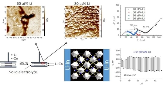
Lithium–indium alloys with different Li contents (from 40 to 90 at%) on the Li7La3Zr2O12-based solid electrolyte surface were obtained using an in situ method. A scheme for demonstrating the in situ method of Li-In anode formation is shown in Figure 1. The XRD data of the obtained sample show the presence of different Li-In compounds for all issued compositions (see Supplementary Materials Figure S1). All samples with a Li content of 40 at% and higher showed instability in air with the formation of lithium nitrides or oxides (Figure S2).
The topology of the surface region of the In-Li alloy (60 at% Li) is presented in Figure 2a,b. According to topology maps, the Li-In alloys possess a rugosity up to 700 nm. Figure 2c shows an elastic modulus distribution map of the studied alloy. The presence of two different regions can be observed: the dominating phase with a Young modulus value from 2.8 to 3.0 GPa and a second randomly distributed domain with lower values of Young modulus (2.0–2.4 GPa). In our previous work [21], the presence of two phases was also found in a lithium–indium alloy with 18 at% Li–α-phase (the solid solution phase) and β-phase (LiIn) with Young modulus values of ~3.5–4.0 and ~3.0–3.2 GPa, respectively. So, it can be assumed that in the alloy obtained, the phase with an elastic modulus of about 2.8–3.0 GPa corresponds to LiIn. The second phase, according to the phase diagram of the Li-In system, can be attributed to the γ-phase [24]. Li-In alloy with a higher lithium content (80 at%) was also analyzed using atomic force microscopy. The phases with separate grains are not observed on its topology map (Figure 3). According to the literature data [25], Li and In metals are characterized by elastic modulus values of ~5.0 and 11 GPa, respectively. Therefore, we can conclude that the obtained alloys have no pure metal inclusions.
Figure 4a shows the impedance plots of Li-In (80 at% Li)|LLZcomp|Li-In (80 at% Li) cells. After heating for 2 h, a slight decrease in the symmetric cell resistance can be observed due to the In-Li alloy formation. Then, the resistance values did not change further. Figure 4b shows the impedance plots for the assembled symmetric cells after their heating for 2 h. The total resistance of the cells can be determined from the intersection of the semicircle with the abscissa axis (Z′). An equivalent circuit is also given in Figure 4a: the total cell resistance presents the sum of the of the solid membrane resistance (Rel) and the interfacial resistance between LLZ-based solid electrolyte and lithium–indium electrodes (R1). The fitting results are presented in Table S1. The obtained impedance plots start at Z′ > 0; therefore, the solid electrolyte resistance can be determined as a low-resistance R-value during the arc fitting. It should be noted that the obtained values were in good agreement with the impedance spectroscopy results collected for composite solid electrolyte using GaAg electrodes. The value of the total resistance of the symmetric cells decreases from 98 to 28 Ω cm2 with increasing lithium content in the alloy. All the samples are ascribed as containing two or more different lithium–indium compounds, which might be the reason for the differences in R1 resistance values on the impedance plots. We observed decreases in resistance along with In content in composition. The R1 corresponds to two symmetric interfaces; therefore, the interfacial resistance between the Li-In anode and composite electrolyte can be calculated by dividing the diameter of a semicircle by two. So, the resistance at the interface between Li-In (90 at% Li) and LLZ-based solid electrolyte is equal to ~11 Ω cm2.
The starting cell voltage under no current applied was around 0 V, which is normal for symmetric cells with identical electrodes. Cyclic voltammetry data were obtained under potential scanning in a range of ±500 mV relative to open-circuit voltage (OCV) with a scanning rate of 10 mV s−1. The voltametric curves of the assembled cells with Li-In alloy (40 and 90 at% Li) are presented in Figure 5. It can be seen that the currents of 12–18 mA cm−2 pass through the cells under the applied potential of ±500 mV. The curves were reproducible, assuming the absence of irreversible processes under current direction changes (charge/discharge of the cells). It should be noted that currents of ~4 μA cm−2 pass through the symmetric cell with 18 at% Li in the lithium–indium alloy (ex situ method), which is thousands of times less (Figure S3a). The Li|LLZcomp|Li symmetric cell possesses an ultimate current density as high as ~20 μA cm−2 (Figure S3b).
We also carried out the galvanostatic cycling of the assembled cells with different Li contents in the alloys under a current of ±1 and 8 mA (5 and 40 mA cm−2) (Figure 6 and Figure 7). The potential overloads are observed during the first 10 h in symmetric cells with a low content of lithium in the alloy (40–60 at% Li) (Figure 5). With an increase in the current passing time, a more stable operation of the cell is observed. Such unstable behavior at the beginning of cycling may be associated with the process of interface formation between the Li-In alloy and solid electrolyte. Notably, the symmetric cells with a lower content of indium in the Li-In electrode (80–90 at% Li) show a more stable behavior during cycling (Figure 7). The increase of voltage values with time was not observed, which indicates the stability of the symmetric cells during the experiment.
Micrographs of the cross-section of the Li-In|LLZcomp|Li-In cells with different Li contents in the alloys after the cycling test are shown in Figure 8. It can be seen that the alloys obtained present a homogeneous mass, which indicates the successful interaction of deposited In and Li layers and the formation of the Li-In alloy. The Li-In anode obtained by the in situ method forms a close contact with the Li7La3Zr2O12-based solid electrolyte. Large voids at the electrode–electrolyte interface, as in the case of the Li–Li6.6Al0.05La3Zr1.75Nb0.25O12 interface, are not observed for all issued Li-In contents [26].
The phase composition of the ceramics surface after the experiments was investigated by XRD and Raman spectroscopy analysis. The formation of any impurity phases at the LLZcomp|Li-In alloy interface with different lithium contents (40–90 at%) was not detected, either after contact with the alloy or after the cycling of symmetric cells (Figure 9a). The absence of interaction is also confirmed by Raman spectroscopy analysis (Figure 9b). So, according to Raman spectroscopy and XRD data, no degradation of the composite electrolyte occurred after contact with the lithium–indium anode, and galvanostatic cycling did not occur. Therefore, the Li-In alloy obtained by our in situ method can be used as an anode in lithium power sources.
4. Conclusions
The Li-In anodes with different lithium contents (40–90 at% Li) in the alloy were obtained by an in situ method on the Li7La3Zr2O12 solid electrolyte substrate. The Li-In alloy formation was confirmed by AFM data; furthermore, according to Young modulus maps, the alloys obtained have no pure metal inclusions. The total resistance of the Li-In–LLZcomp–Li-In symmetrical cells decreases with lithium content growth in the Li-In alloy. It was established that Li-In (90 at% Li)|LLZ-based solid electrolyte interface resistance is equal to ~11 Ω cm2 at 200 °C. The symmetric cells with a low content of lithium in the alloy (40–60 at% Li) demonstrated potential overloads during the first 10 h, and a more stable operation of the cell was observed after the increase in the current passing time. The cells with 80–90 at% Li in the Li-In electrode show a more stable behavior during cycling with an applied current of ±8 mA (40 mA cm−2).
According to scanning electron microscopy data, the use of a lithium–indium alloy as an anode with the initial deposition of In on the lithium-conducting electrolyte of LLZ family leads to the formation of a tight contact between Li-In and LLZc + 1 wt% LYS. This leads to resistance reduction at the anode|solid electrolyte interface and the stable operation of the cells over time with the applied current of ±40 mA cm−2. Using XRD and Raman spectroscopy, it was shown that the composite electrolyte does not degrade in contact with lithium–indium alloys of different compositions after electrochemical experiments. Thus, the results obtained in the presented work can be used for the creation of all-solid-state power sources with a Li-In anode.
Supplementary Materials
The following supporting information can be downloaded at: https://www.mdpi.com/article/10.3390/batteries8110226/s1, Figure S1: XRD data of Li-In anode with 60 (a) and 90 at% Li (b); Figure S2: XRD data of Li-In anode with 60 at% Li after exposure on air; Table S1: The fitting results of impedance plots at Figure 4b; Figure S3: Cyclic voltammetry curves for (a) Li-In (18 at% Li)|LLZcomp|Li-In (18 at% Li) and (b) Li|LLZcomp|Li cells with at scanning rate of 10 mV s-1.
Author Contributions
Conceptualization, E.I. and K.D.; investigation, E.I., K.D., E.L., and I.T.; data curation, E.I. and K.D.; writing—original draft preparation, E.I. and K.D.; writing—review and editing, E.I. and K.D.; supervision, E.I.; funding acquisition, E.I. All authors have read and agreed to the published version of the manuscript.
Funding
This work was partly supported by the grant of the President of the Russian Federation [№ MK-4015.2021.1.3]. The AFM study of Li-In alloy was funded by the Russian Academy of Sciences, Ural Branch, Russia [No. 122020100210-9 (IHTE UB RAS)].
Data Availability Statement
Not applicable.
Acknowledgments
The authors are grateful to Antonov, B.D.; Pankratov, A.A.; and Vovkotrub E.G. The research has been carried out using equipment from the Shared Access Center “Composition of Compounds” at the Institute of High Temperature Electrochemistry.
Conflicts of Interest
The authors declare that they have no conflict of interest.
References
- Bates, A.M.; Preger, Y.; Torres-Castro, L.; Harrison, K.L.; Harris, S.J.; Hewson, J. Are solid-state batteries safer than lithium-ion batteries? Joule 2022, 6, 742–755. [Google Scholar] [CrossRef]
- Guo, Y.; Wu, S.; He, Y.B.; Kang, F.; Chen, L.; Li, H.; Yang, Q.H. Solid-state lithium batteries: Safety and prospects. eScience 2022, 2, 138–163. [Google Scholar] [CrossRef]
- Xu, L.; Lu, Y.; Zhao, C.-Z.; Yuan, H.; Zhu, G.-L.; Hou, L.-P.; Zhang, Q.; Huang, J.-Q. Toward the Scale-Up of Solid-State Lithium Metal Batteries: The Gaps between Lab-Level Cells and Practical Large-Format Batteries. Adv. Energy Mater 2021, 11, 2002360. [Google Scholar] [CrossRef]
- Kong, L.; Wang, L.; Zhu, J.; Bian, J.; Xia, W.; Zhao, R.; Lin, H.; Zhao, Y. Configuring solid-state batteries to power electric vehicles: A deliberation on technology, chemistry and energy. Chem. Commun. 2021, 57, 12587–12594. [Google Scholar] [CrossRef] [PubMed]
- Chen, L.; Huang, Y.F.; Ma, J.; Ling, H.; Kang, F.; He, Y.B. Progress and perspective of all-solid-state lithium batteries with high performance at room temperature. Energy Fuels 2020, 34, 13456–13472. [Google Scholar] [CrossRef]
- Sun, C.; Liu, J.; Gong, Y.; Wilkinson, D.P.; Zhang, J. Recent advances in all-solid-state rechargeable lithium batteries. Nano Energy 2017, 33, 363–386. [Google Scholar] [CrossRef] [Green Version]
- Kammampata, S.P.; Thangadurai, V. Cruising in ceramics—discovering new structures for all-solid-state batteries—fundamentals, materials, and performances. Ionics 2018, 24, 639–660. [Google Scholar] [CrossRef]
- Liu, Q.; Geng, Z.; Han, C.; Fu, Y.; Li, S.; He, Y.B.; Kang, F.; Li, B. Challenges and perspectives of garnet solid electrolytes for all solid-state lithium batteries. J. Power Sources 2018, 389, 120–134. [Google Scholar] [CrossRef]
- Zheng, F.; Kotobuki, M.; Song, S.; Lai, M.O.; Lu, L. Review on solid electrolytes for all-solid-state lithium-ion batteries. J. Power Sources 2018, 389, 198–213. [Google Scholar] [CrossRef]
- Ramakumar, S.; Deviannapoorani, C.; Dhivya, L.; Shankar, L.S.; Murugan, R. Lithium garnets: Synthesis, structure, Li+ conductivity, Li+ dynamics and applications. Prog. Mater. Sci. 2017, 88, 325–411. [Google Scholar] [CrossRef]
- Il’ina, E.A.; Raskovalov, A.A. Studying of superionic solid electrolyte Li7La3Zr2O12 stability by means of chemical thermodynamics for application in all-solid-state batteries. Electrochim. Acta 2020, 330, 135220. [Google Scholar] [CrossRef]
- Huang, W.; Zhao, N.; Bi, Z.; Shi, C.; Guo, X.; Fan, L.; Nan, C. Can We Find Solution to Eliminate Li Penetration through Solid Garnet Electrolytes? Mater. Today Nano 2020, 10, 100075. [Google Scholar] [CrossRef]
- Lou, J.; Wang, G.; Xia, Y.; Liang, C.; Huang, H.; Gan, Y.; Tao, X.; Zhang, J.; Zhang, W. Achieving efficient and stable interface between metallic lithium and garnet-type solid electrolyte through a thin indium tin oxide interlayer. J. Power Sources 2020, 448, 227440. [Google Scholar] [CrossRef]
- Bai, L.; Xue, W.; Li, Y.; Liu, X.; Li, Y.; Sun, J. The interfacial behaviors of all-solid-state lithium ion batteries. Ceram. Int. 2018, 44, 7319–7328. [Google Scholar] [CrossRef]
- Obrovac, M.N.; Chevrier, V.L. Alloy Negative Electrodes for Li-Ion Batteries. Chem. Rev. 2014, 114, 11444–11502. [Google Scholar] [CrossRef]
- Gu, X.; Dong, J.; Lai, C. Li-containing alloys beneficial for stabilizing lithium anode: A review. Eng. Rep. 2020, 3, 12339. [Google Scholar] [CrossRef]
- Santhosha, A.L.; Medenbach, L.; Buchheim, J.R.; Adelhelm, P. The Indium-Lithium electrode in solid-state lithium ion batteries: Phase formation, redox potentials and interface stability. Batter. Supercaps 2019, 2, 524–529. [Google Scholar] [CrossRef]
- Alexander, G.V.; Sreejith, O.V.; Indu, M.S.; Murugan, R. Interface-compatible and high-cyclability lithiophilic lithium-zinc alloy anodes for garnet-structured solid electrolytes. ACS Appl. Energy Mater. 2020, 3, 9010–9017. [Google Scholar] [CrossRef]
- Krauskopf, T.; Mogwitz, B.; Rosenbach, C.; Zeier, W.G.; Janek, J. Diffusion limitation of lithium metal and Li–Mg alloy anodes on LLZO type solid electrolytes as a function of temperature and pressure. Adv. Energy Mater. 2019, 9, 1902568. [Google Scholar] [CrossRef] [Green Version]
- Liang, X.; Pang, Q.; Kochetkov, I.R.; Sempere, M.S.; Huang, H.; Sun, X.; Nazar, L.F. A facile surface chemistry route to a stabilized lithium metal anode. Nat. Energy 2017, 2, 17119. [Google Scholar] [CrossRef]
- Il’ina, E.A.; Druzhinin, K.V.; Lyalin, E.D.; Plekhanov, M.S.; Talankin, I.I.; Antonov, B.D.; Pankratov, A.A. Li-In alloy: Preparation, properties, wettability of solid electrolytes based on Li7La3Zr2O12. J. Mater. Sci. 2022, 57, 1291–1301. [Google Scholar] [CrossRef]
- Il’ina, E.A.; Druzhinin, K.V.; Antonov, B.D.; Pankratov, A.A.; Vovkotrub, E.G. Influence of Li2O–Y2O3–SiO2 glass additive on conductivity and stability of cubic Li7La3Zr2O12. Ionics 2019, 25, 5189–5199. [Google Scholar] [CrossRef]
- Il’ina, E.A.; Druzhinin, K.V.; Antonov, B.D. Stability of composite electrolytes based on Li7La3Zr2O12 to metallic lithium. Ionics 2020, 26, 163–172. [Google Scholar] [CrossRef]
- Alexander, W.A.; Calvert, L.D.; Gamble, R.H.; Schinzel, K. The lithium-indium system. Can. J. Chem. 1976, 54, 1052–1060. [Google Scholar] [CrossRef]
- Cardarelli, F. Less common nonferrous metals. In Materials Handbook; Springer: Cham, Switzerland, 2018; pp. 317–695. [Google Scholar] [CrossRef]
- Il’ina, E.A.; Druzhinin, K.V.; Lyalin, E.D.; Antonov, B.D.; Pankratov, A.A.; Vovkotrub, E.G.; Pryakhina, V.I. Influence of Al layer thickness on Li6.6Al0.05La3Zr1.75Nb0.25O12 solid electrolyte|Li anode interface in all-solid-state batteries. Solid State Ion. 2021, 370, 115736. [Google Scholar] [CrossRef]
Figure 1.
The scheme for demonstrating the in situ method.

Figure 2.
Topology (a,b) and Young modulus maps (c) of the In-Li (60 at% Li) alloy.


Figure 3.
Topology (a) and Young modulus maps (b) of the In-Li (80 at% Li) alloy.


Figure 4.
Impedance plots at 200 °C of Li-In|LLZcomp|Li-In cells after different heating times (a) and with different lithium contents in alloy (b).
Figure 4.
Impedance plots at 200 °C of Li-In|LLZcomp|Li-In cells after different heating times (a) and with different lithium contents in alloy (b).

Figure 5.
Cyclic voltammetry curves for Li-In|LLZcomp|Li-In cells with 40 (a) and 80 (b) at% Li at scanning rate of 10 mV s−1.
Figure 5.
Cyclic voltammetry curves for Li-In|LLZcomp|Li-In cells with 40 (a) and 80 (b) at% Li at scanning rate of 10 mV s−1.


Figure 6.
Galvanostatic cycling data of the Li-In (40 at% Li)|LLZcomp|Li-In (40 at% Li) symmetric cell with the applied current of ±1 mA at 200 °C.
Figure 6.
Galvanostatic cycling data of the Li-In (40 at% Li)|LLZcomp|Li-In (40 at% Li) symmetric cell with the applied current of ±1 mA at 200 °C.

Figure 7.
Galvanostatic cycling data of the Li-In (90 at% Li)|LLZcomp|Li-In (90 at% Li) cell with applied current of ±8 mA at 200 °C.
Figure 7.
Galvanostatic cycling data of the Li-In (90 at% Li)|LLZcomp|Li-In (90 at% Li) cell with applied current of ±8 mA at 200 °C.

Figure 8.
SEM images of the cross-section of Li-In|LLZcomp|Li-In cells with 40 (a) and 90 (b) at% Li.
Figure 8.
SEM images of the cross-section of Li-In|LLZcomp|Li-In cells with 40 (a) and 90 (b) at% Li.


Figure 9.
XRD patterns (a) and Raman spectra (b) of LLZc + 1 wt% LYS solid electrolyte surface after contact with lithium–indium anode.
Figure 9.
XRD patterns (a) and Raman spectra (b) of LLZc + 1 wt% LYS solid electrolyte surface after contact with lithium–indium anode.


Table 1.
The theoretical capacity value of anode materials.
| Composition | C, mA h g−1 |
|---|---|
| Li | 3861 |
| 90 Li–10 In | 1361 |
| 80 Li–20 In | 752 |
| C6 | 372 |
| 60 Li–40 In | 321 |
| 40 Li–60 In | 150 |
| 18 Li–82 In | 51 |
| 10 Li–90 In | 26 |
Publisher’s Note: MDPI stays neutral with regard to jurisdictional claims in published maps and institutional affiliations. |
© 2022 by the authors. Licensee MDPI, Basel, Switzerland. This article is an open access article distributed under the terms and conditions of the Creative Commons Attribution (CC BY) license (https://creativecommons.org/licenses/by/4.0/).
Share and Cite
MDPI and ACS Style
Il’ina, E.; Druzhinin, K.; Lyalin, E.; Talankin, I. In Situ Li-In Anode Formation on the Li7La3Zr2O12 Solid Electrolyte in All-Solid-State Battery. Batteries 2022, 8, 226. https://doi.org/10.3390/batteries8110226
AMA Style
Il’ina E, Druzhinin K, Lyalin E, Talankin I. In Situ Li-In Anode Formation on the Li7La3Zr2O12 Solid Electrolyte in All-Solid-State Battery. Batteries. 2022; 8(11):226. https://doi.org/10.3390/batteries8110226
Chicago/Turabian StyleIl’ina, Evgeniya, Konstantin Druzhinin, Efim Lyalin, and Ilua Talankin. 2022. "In Situ Li-In Anode Formation on the Li7La3Zr2O12 Solid Electrolyte in All-Solid-State Battery" Batteries 8, no. 11: 226. https://doi.org/10.3390/batteries8110226
Note that from the first issue of 2016, this journal uses article numbers instead of page numbers. See further details here.