Article

Effects of Excessive Prelithiation on Full-Cell Performance of Li-Ion Batteries with a Hard-Carbon/Nanosized-Si Composite Anode

1
Joint Research Center for Electric Architecture, Akita University, 1-1 Tegatagakuen-machi, Akita 010-8502, Japan
2
Department of Mathematical Science and Electrical-Electronic-Computer Engineering, Akita University, 1-1 Tegatagakuen-machi, Akita 010-8502, Japan
*
Author to whom correspondence should be addressed.
Batteries 2022, 8(11), 210; https://doi.org/10.3390/batteries8110210
Submission received: 13 September 2022 / Revised: 16 October 2022 / Accepted: 29 October 2022 / Published: 2 November 2022
(This article belongs to the Special Issue Feature Papers to Celebrate the First Impact Factor of Batteries)

Abstract

:
The effects of excessive prelithiation on the full-cell performance of Li-ion batteries (LIBs) with a hard-carbon/nanosized-Si (HC/N-Si) composite anode were investigated; HC and N-Si simply mixed at mass ratios of 9:1 and 8:2 were analyzed. CR2032-type half- and full-cells were assembled to evaluate the electrochemical LIB anode behavior. The galvanostatic measurements of half-cell configurations revealed that the composite anode with an 8:2 HC/N-Si mass ratio exhibited a high capacity (531 mAh g−1) at 0.1 C and superior current-rate dependence (rate performance) at 0.1–10 C. To evaluate the practical LIB anode performance, the optimally performing composite anode was used in the full cell. Prior to full-cell assembly, the composite anodes were prelithiated via electrochemical Li doping at different cutoff anodic specific capacities (200–600 mAh g−1). The composite anode was paired with a LiNi0.5Co0.2Mn0.3O2 cathode to construct full-cells, the performance of which was evaluated by conducting sequential rate and cycling performance tests. Prelithiation affected only the cycling performance, without affecting the rate performance. Excellent capacity retention was observed in the full-cells with prelithiation conducted at cutoff anodic specific capacities greater than or equal to 500 mAh g−1.

1. Introduction

Li-ion batteries (LIBs) with high energy and/or power densities are desired for a wide variety of applications, such as portable electronic devices, electric vehicles, and grid storage systems [1,2,3]. Generally, electric-powered devices require optimal LIB systems with a specified voltage and electrical capacity; these are constructed using parallel/serial-connected LIB cells. Increasing the energy and power densities of each LIB cell allows these LIB systems to achieve miniaturization, weight, and cost reduction, as well as the economical consumption of battery materials. Graphite—a popular anode-active material—is primarily used in LIB anodes owing to its low working potential (~0 V vs. Li/Li+), relatively high lithiation capacity (~350 mAh g−1), and low cost [4,5,6]. Moreover, composite anodes comprising multiple anode-active materials are frequently used as LIB anodes. Simply mixing two types of active materials is a promising approach for achieving enhanced performance in terms of parameters such as capacity, current rate dependence, and cycle life [7,8,9,10,11,12,13,14,15,16,17,18,19,20,21]. Composite anodes are typically fabricated using graphite, other carbon materials such as hard carbon (HC), carbon black, graphene, and carbon nanotubes, as well as Si or Si oxides at specific mass ratios. Kierzek and Machnikowski discussed the practical aspects of Si/graphite composite anodes in a full-cell configuration [12]. Ge et al. synthesized composite anodes using two types of carbon materials (HC and graphite) and highlighted the importance of HC loading on the composite anodes [13]. Hu et al. examined the effects of the prelithiation of a polyacrylic acid (PAA) binder on the operation of a Si/graphite composite anode in full cells [15]. Kim et al. fabricated graphite/Si composite anodes and evaluated their performance in half- and full-cell configurations [18]. In their study, graphite was used as the main active material for the composite anodes at considerably high mass ratios (>65 mass%). This indicates that composite anodes continue to be dependent on graphite.
HC, which is an alternative anode-active material to graphite, is an amorphous carbon with a disordered structure containing randomly arranged single graphene sheets [22]. The structure of HC facilitates its high lithiation capacity and buffer effect during lithiation and delithiation [23,24]. Although HC has a few drawbacks (high irreversible capacity, low Coulombic efficiency (CE), and low tap density), its use can assist in alleviating the mechanical stress in the anode, thereby enabling a longer cycle life and improved power capability suited for power-type LIBs. Si has also garnered significant attention as a substitute anode-active material for graphite. Each Si atom electrochemically alloys with 4.4 Li atoms to form Li4.4Si, which exhibits a remarkably high specific capacity at full Li alloying (4200 mAh g−1) [25,26]. However, Si particles cause a volume expansion of approximately 400 vol.% during lithiation, leading to cracks on the surface of the electrode or in its interior and the pulverization of Si, thereby degrading the anode performance [14,17]. Furthermore, the electrical conductivity of Si is not as high as that of carbon materials. In recent studies, nanosized Si (N-Si) particles have been found to exhibit superior anode performance compared with that of conventional Si-based anodes, in addition to having less mechanical stress without critical performance degradation [5,7,9,27,28,29]. Particle size reduction is effective for overcoming the aforementioned disadvantages of Si-based anodes. Attempts can also be made to increase the electrical conductivity by adding carbon materials, such as HC and carbon black, and exploiting the buffer effect to mitigate the volume expansion/contraction during lithiation and delithiation.
Composite anodes containing C, Si, and/or Si oxides are typically paired with a Li transition metal oxide cathode in full-cell configurations. To achieve charge–discharge stability and safety and longer cycle life, and to prevent Li deposition on the anode, the capacity design for the anode and cathode must be performed in a balanced manner, which depends on their respective active materials [30,31,32,33]. The capacities of the cathode and anode are determined by the specific capacity and loading of the active material coated on the current collector. In general, the specific capacity of cathodes such as ternary Li transition metal oxides is limited to ~200 mAh g−1. However, the theoretical specific capacity of pure Si is 4200 mAh g−1, which is 21 times higher than that of the cathode. The anode/cathode capacity ratio is tuned to be greater than 1.0 (anode-capacity-rich design) to prevent Li-dendrite formation on the anode surface [34,35]. However, adjusting this capacity ratio is difficult for Si-based full-cell LIBs owing to the significant difference in the capacity between their cathode and anode. To overcome these problems, anodes with unique shapes such as ultrathin films and those with a considerably low loading have been fabricated using special processing techniques. However, these electrode fabrication processes are fairly complex and time- and cost-intensive. Thus, the Si-based composite anode with a low Si mass ratio is a realistic option for electrode fabrication and capacity design for LIB full cells. Additionally, a mixture of Si and carbon materials could improve the electrical conductivity, lithiation capacity, power capability, and cycle life and alleviate mechanical stress.
Si- or HC-based anodes exhibit high irreversible capacities and low CEs in the initial cycle; the high irreversible capacities are due to electrolyte decomposition on the anode side, Li traps in the macro-/nanopores in the HC, and the passivation of Si during Li alloying [22,36]. The prelithiation of anodes is known to be essential for reducing the irreversible capacity and enhancing CE [24,37,38,39]. Prelithiation is achieved using various mechanical or electrochemical methods [18,28,40], such as through (i) the direct contact of the anode with Li metal in the electrolyte, (ii) the addition of stabilized Li metal powder during the anode fabrication, and (iii) the electrochemical Li doping of the anode in a half-cell configuration (anode/Li cell). Among these methods, electrochemical Li doping can accurately control the amount of Li dopant. Doping Li ions into the anode and assembling a full-cell can lead to an excess of Li in the cell, which can unfortunately influence the operation and safety of the full-cell and degrade its performance. Accurately controlled prelithiation can help prevent Li-dendrite formation on the anode surface, permit safe full-cell operation, and suppress the performance degradation of LIB full-cells. Moreover, adding HC that exhibits a decent buffer effect on the anode can establish good electrical contact with the anode and enhance its robustness. Although the effects of the performance of prelithiated sole HC anodes have been extensively examined to date, the performance of prelithiated Si/HC composite anodes has hardly been examined. Furthermore, the impact of the amount of Li compensated through prelithiation on the HC/Si composite anode performance in a full-cell configuration is unknown.
Therefore, composite anodes were fabricated in this study by simply mixing N-Si and HC. The HC/N-Si mass ratio was varied (9:1 and 8:2) during the anode fabrication. The performance of the prepared anodes was evaluated by conducting galvanostatic measurements to evaluate lithiation and delithiation at a low current density as well as the current rate dependence. Instead of the HC- and graphite-only anodes, a promising composite anode was selected, prelithiated, and then incorporated into full-cells with a LiNi0.5Co0.2Mn0.3O2 (NCM523) cathode. The composite anodes were prelithiated in a decomposable test cell with a Li metal foil; the cell was operated in constant-current mode until the predefined cutoff anodic specific capacities (200, 300, 400, 500, and 600 mAh g−1) were achieved. Subsequently, the effects of prelithiation on the HC/N-Si composite anode performance in full-cells were investigated and comprehensively analyzed.

2. Results and Discussion

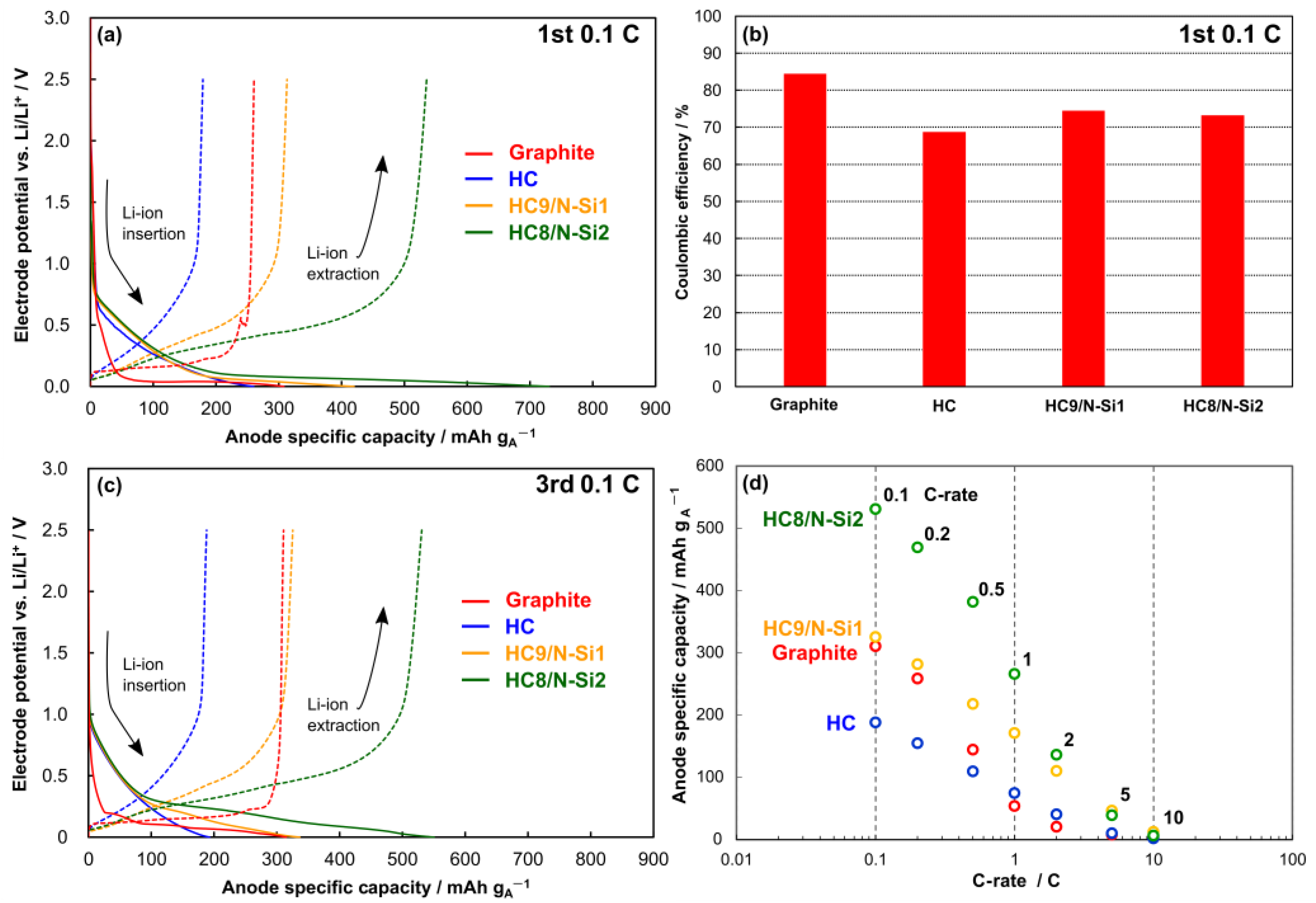
2.1. Half-Cell Evaluation

Figure 1 shows the anode performance of the half-cell configuration. A graphite anode was used for comparison. The lithiation- and delithiation-specific capacities were clearly enhanced at the higher N-Si mass ratio. In the first cycle, the delithiation-specific capacity was lower than that of lithiation. This was due to electrolyte decomposition at the anode–electrolyte interface, where active Li ions were consumed by the electrolyte to form a stable and passive film, which is often called a solid–electrolyte interphase (SEI) film. The CE in the first cycle determines the degree of consumption of the active Li ions inside the cell. The graphite anode had a high CE of 84.5%, as well as a plateaued, low-potential curve. However, the HC, which exhibited a slope-like potential curve, showed a low CE of 68.9%. Moreover, blending the HC and N-Si improved the CE compared with that of sole HC, yielding values of 74.6% for HC9/N-Si1 and 73.3% for HC8/N-Si2. As the anodes were composed of HC and N-Si, the shapes of the potential curves of the blended active materials did not show significant changes compared with that of the HC.
By achieving first-cycle lithiation and delithiation after cell assembly, the anode was activated to store full Li ions in the active material. In the third cycle, all the anodes exhibited a stable specific capacity, with sole graphite and HC showing values of 311 and 188 mAh gA−1, respectively, during the delithiation. The combination of HC and N-Si in the anode enhanced the specific capacity; in particular, HC8/N-Si2 exhibited the maximum delithiation-specific capacity among the anodes (531 mAh gA−1). As the C-rate was increased from 0.1 to 10 C (Figure 1d), the blended active materials exhibited higher specific capacities. Even at 2 and 5 C, their delithiation-specific capacities were higher than those of the sole active materials. The maximum specific capacity of HC9/N-Si1 was similar to that of graphite at <0.5 C but increased thereafter. A comparison between graphite and HC9/N-Si1 suggests that the current rate dependence of the former was inferior to that of the latter [6,9,16].

2.2. Physical Characterization of Materials and Electrodes

The physical properties of the active materials used to fabricate the anodes are summarized in Table 1. Graphite and HC had micron-sized particles (10–16 μm) and lower Brunauer–Emmett–Teller (BET)-specific surface areas (<8.2 m2 g−1) than N-Si (35.2 m2 g−1). However, the evaluation of the particle size of N-Si by laser-diffraction particle size measurement using a wet method was difficult because the nanosized particles readily agglomerated in the solution. The measured value (1.1 μm) corresponded to the agglomerated N-Si particles; therefore, the true particle size was determined to be 0.1 μm using specification-related data [41].
The morphology, particle size, and elemental distributions for HC and N-Si particles were analyzed using scanning electron microscopy (SEM) and energy-dispersive X-ray spectroscopy (EDX) elemental maps (Figure 2a). Although N-Si was agglomerated with several particles, the particle size was determined to be ~0.1 μm with a spherical shape. The particle size of HC was ~10-μm with angulated outlines. The elemental mappings of C or Si, and O revealed the elemental distribution at the particle surface. In addition to the main component of C or Si, a small amount of O was observed in the particles; other elements were not detected in the EDX elemental maps. The HC8/N-Si2 composite anode, which showed optimal anode performance among the investigated anodes, was analyzed via SEM and EDX (Figure 2b–f). HC particles as large as 10 µm were observed on the anode surface. A sponge-like substance containing the conductive agent and PAA binder was firmly attached to the HC particles. Moreover, a few voids were observed in the anode (red dotted lines in Figure 2b), implying the creation of a void structure inside the coating layer of the anode. In the cross-sectional analysis (Figure 2d–f), the distributions of C, O, and Si were surveyed along the depth direction. Interestingly, C and Si mapping revealed that N-Si occupied the space between the large HC particles. O was detected in the anode because of the oxidation of the HC and/or N-Si particles.

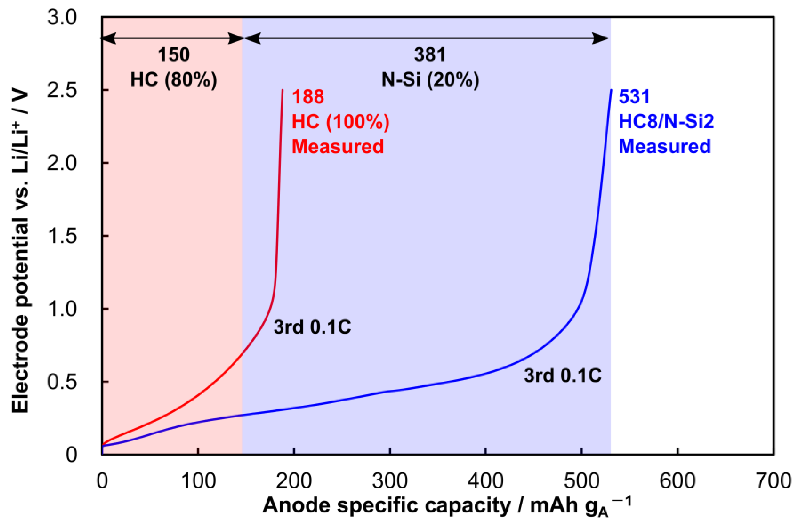
2.3. Specific Capacity of HC8/N-Si2 Anode

Figure 3 shows the acquired delithiation curves for the HC and HC8/N-Si2 anodes as well as the specific capacity assignment of the HC and N-Si components of HC8/N-Si2. A half-cell evaluation at 0.1 C in the third cycle yielded an effective specific capacity of 531 mAh gA−1 for the composite, with the HC-only anode showing a lower value of 188 mAh gA−1. The HC accounted for approximately 80 mass% of the active material in HC8/N-Si2. Therefore, HC contributed 80% of 188 mAh gA−1 as the partial specific capacity to the blended active material, with the rest being supplied by N-Si (381 mAh gA−1). The apparent specific capacity of N-Si at full Li alloying was calculated to be 1905 mAh gA−1, which is approximately half the theoretical specific capacity of pure Si (4200 mAh gA−1). This was presumably related to the degree of the oxidation and morphology of Si, as well as electrode design aspects, such as the component ratio of active and inactive materials and types of conductive agent and binder materials [28,42,43]. Therefore, the HC8/N-Si2 anode was estimated to have a specific capacity of 530 mAh gA−1.

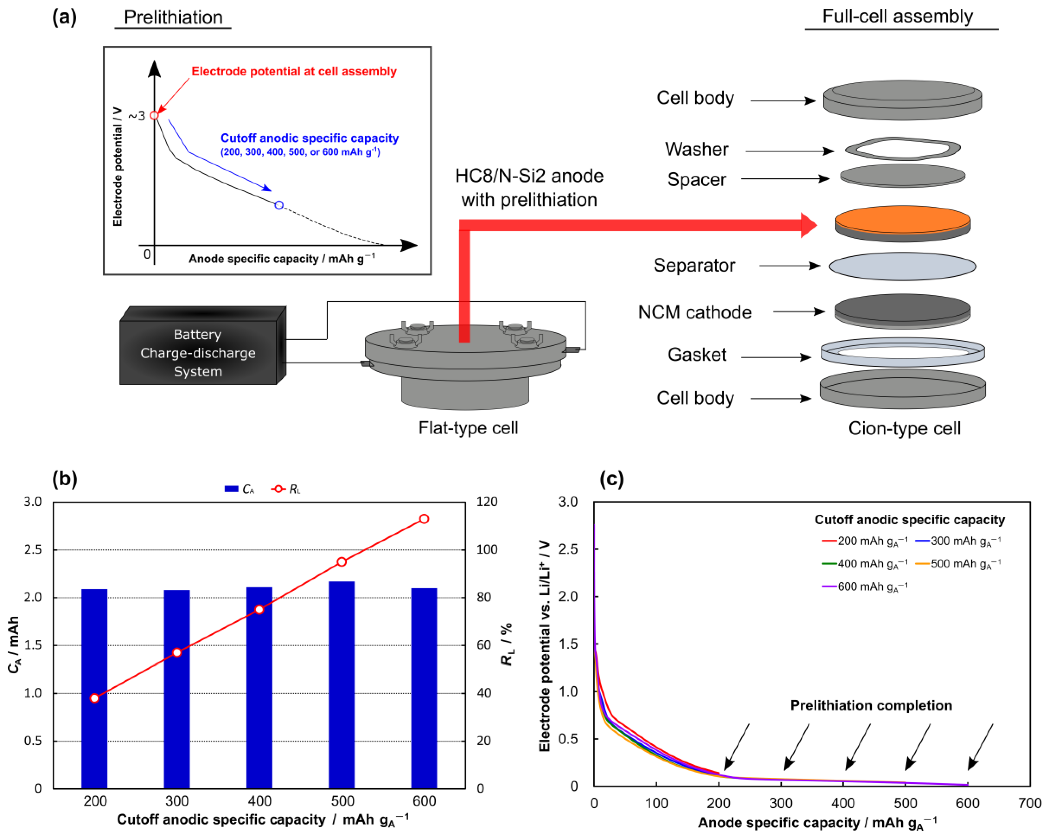
2.4. Anode Prelithiation and Full-Cell Assembly

Figure 4 shows a schematic of the prelithiation process and the corresponding results obtained using the HC8/N-Si2 composite anode in a full-cell configuration. Prelithiation was realized by operating a decomposable test cell with a Li metal foil and the HC8/N-Si2 anode (prelithiation cell) electrochemically doped with certain Li ions. Subsequently, the anode was incorporated into a full-cell with an NCM523 cathode (Figure 4a). The prelithiation capacity was controlled by setting a cutoff anodic specific capacity (200, 300, 400, 500, or 600 mAh gA−1). The prelithiation rate (RL) was calculated as follows:
R L = C L C A
where CL is the measured prelithiation capacity, and CA is the anode capacity calculated using the estimated specific capacity (530 mAh gA−1) and mass of the anode-active material. All the prelithiated cells showed similar CA values of ~2.0 mAh. RL increased proportionally with increasing cutoff anodic specific capacity from 200 to 500 mAh gA−1 and showed the highest value (113%) at a cutoff anodic specific capacity of 600 mAh gA−1. At the electrode level, the prelithiation process corresponding to 113% RL allowed an excess of Li ions into the HC8/N-Si2 composite anode.
The open-circuit voltage (electrode potential vs. Li/Li+) was measured to be ~3 V for all the prelithiated cells using a digital tester immediately after cell assembly. During the prelithiation process, the voltage decreased until the cutoff anodic specific capacity was achieved. Similar potential profiles were exhibited by all the prelithiated cells; however, the electrode potential at the completion of the prelithiation process was different. A reductive reaction associated with SEI formation is known to occur between 0.4 and 1.0 V vs. Li/Li+ for C, Si, and their composites [19,39,44,45,46,47]. During prelithiation, the electrode potential decreased to 0.14, 0.07, 0.06, 0.04, and 0.02 V vs. Li/Li+ for the prelithiated cells with cutoff anodic specific capacities of 200, 300, 400, 500, and 600 mAh gA−1, respectively. These electrode potentials at the end of prelithiation indicate that SEI film formation was almost complete on the anode. Immediately after the SEI film formation, the HC and N-Si likely stored residual Li ions that hardly reacted during the film formation. The HC, which exhibited a slope-like potential below 1.5 V vs. Li/Li+ during Li-ion intercalation and de-intercalation, stored Li ions at the interlayer of randomly arranged graphene sheets (high-potential region) and in micro-/nanopores (low-potential region) [22,48]. The alloying reaction of Si typically occurs at <0.3 V, and the potential is higher than that of Li-ion intercalation in graphite [43,45,46]. Thus, the unconsumed Li ions were mainly stored in the interlayer of the graphene sheets in the HC and Si particles. Furthermore, the different cutoff anodic specific capacities used for prelithiation provided the HC with a varying number of Li ions to store in its graphene sheets.
Table 2 lists the design parameters for the full-cells constructed using an NCM523 cathode and an HC8/N-Si2 composite anode with or without prelithiation (NCM523|HC8/N-Si2 cells). In these experiments, the HC8/N-Si2 composite anode was paired with an NCM523 cathode with an anode/cathode capacity ratio (RA/C) of ~2.0. The cathode capacity (CC) and CA values were calculated using the mass and specific capacity of the active materials (150 mAh gC−1 for NCM523 and 530 mAh gA−1 for HC8/N-Si2). The active material loadings for the cathode (LC) and anode (LA) were 3.9–4.0 and 2.2–2.3 mg cm−2, respectively. The thicknesses of the cathode (tC) and anode (tA) without the current collector were 38–60 and 70–88 μm, respectively. RL and CL increased with an increase in the cutoff anodic specific capacity from 200 to 600 mAh gA−1. The NCM523|HC8/N-Si2 cells are denoted as RLx, where x represents the prelithiation rate (RL).
In order to evaluate the prelithiation process and its effect on the HC8/N-Si2 anode, the margin capacity of the anode before the first lithiation (Max_CLi) was calculated based on the following equation:
M a x _ C Li = C A C E HC 8 / N Si 2 C Li [ mAh ] ,
where CEHC8/N-Si2 is the CE (73.3%) of the HC8/N-Si2 anode at the first cycle in the half-cell configuration. Until RL exceeded 0.95, the prelithiated cells had a margin of Max_CLi to CC, and their anodes were not overcharged beyond the Max_CLi. The Max_CLi of RL95 slightly exceeded the CC, whereas RL113 showed a CC, which was approximately two-fold more than Max_CLi. In these anodes, the overcharge was considered during the first charge.

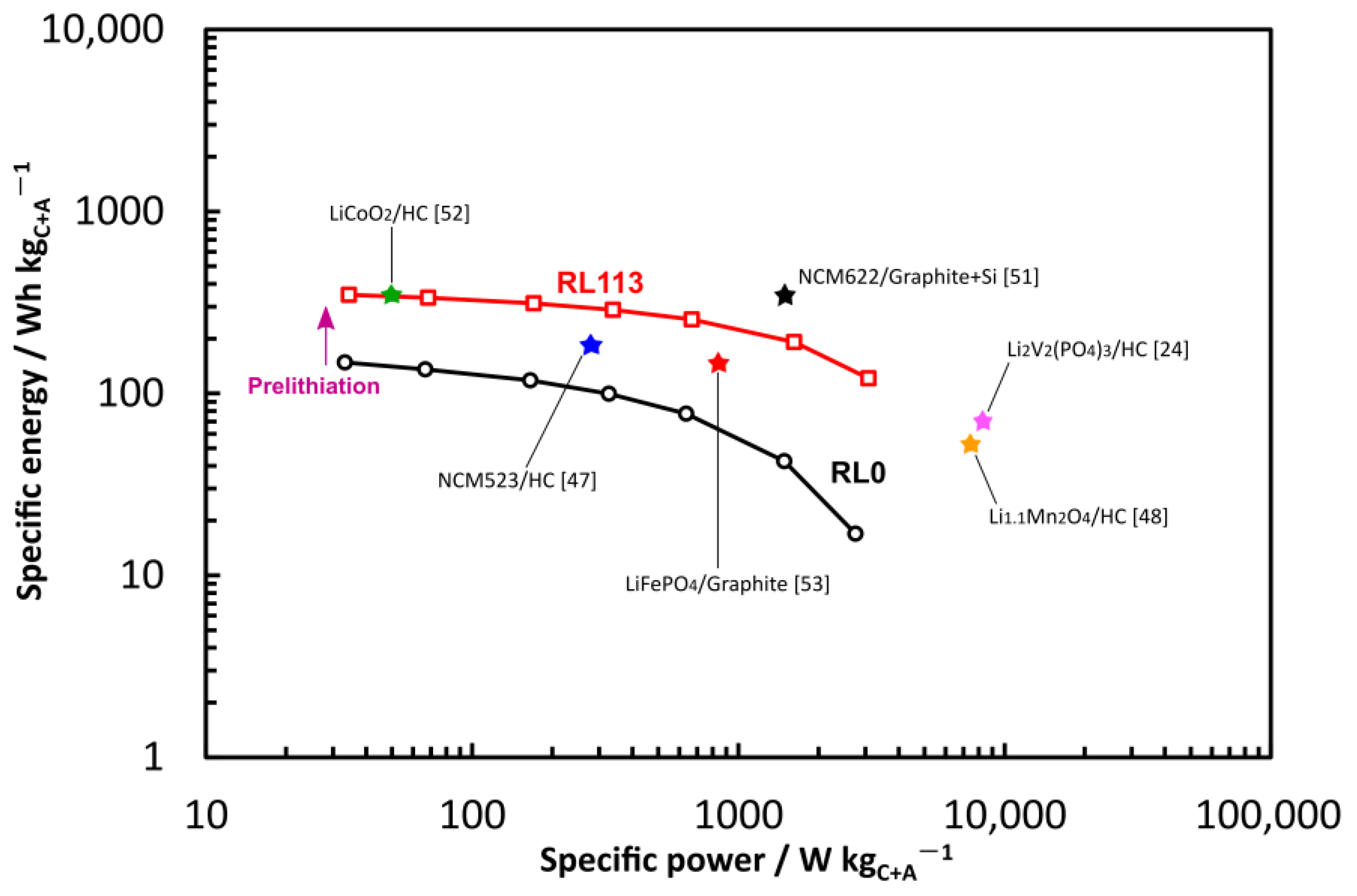
2.5. Full-Cell Evaluation

Figure 5 shows the full-cell performance of the NCM523|HC8/N-Si2 cells with different RL values. In the first cycle, the cell voltage of RL0 increased sharply until a specific capacity of 38 mAh gC−1 and then smoothly reached the cutoff charge voltage of 4.2 V. However, RL113 showed flat-type cell voltage behavior between 3.6 and 4.2 V, except for the initially precipitous drop at 1 mAh gC−1. The other prelithiated cells exhibited similar specific capacity–cell voltage profiles during the first cycle. A spike-like variation was observed at 7 and 1 mAh gC−1 in the profiles of the RL0 and RL113 cells, respectively, which indicates the pristine Li-ion release behavior of ternary Li transition-metal oxides [49,50]. However, the electrolyte decomposition associated with SEI film formation (reduction reaction) occurred at the anode during the first charging process. The electrolyte decomposition during the first charging process occurred simultaneously at both electrodes in RL0; in particular, the electrolyte decomposition reaction at the anode–electrolyte interface was more active, that is, by floating the anode potential and lowering the cell voltage. This behavior was hardly observed in RL113 because the electrolyte decomposition on the anode side was achieved through prelithiation.
At the beginning of the first charging process, a decrease in the cell voltage followed by a precipitous drop was observed for the NCM523|HC8/N-Si2 cells with lower cutoff anodic specific capacities. These voltage variations implied insufficient SEI film formation through prelithiation when the cutoff anodic specific capacity was less than 300 mAh gA−1. The SEI film is generally formed at 0.4–1.0 V vs. Li/Li+ on the anode potential, as mentioned in the previous prelithiation section. The anode potential operates around the reaction potential of SEI film formation, thereby lowering the cell voltage, which was similar to the cell voltage behavior of RL0. Conversely, higher cutoff anodic specific capacity during prelithiation provided the NCM523|HC8/N-Si2 cells with higher operating cell voltage. The RL113 had a higher operating cell voltage than that of RL38 (the difference in the voltage was ~0.1 V). During the subsequent discharge (Figure 5d), all the prelithiated cells operated with an average voltage of 3.5–3.6 V. Li plating on the anode surface in full-cells commonly corresponds to charge or discharge voltage profiles [33,35]. An appropriate and undisturbed charge–discharge profile was observed for each prelithiated cell. Thus, prelithiation with low to high cutoff anodic specific capacity is not likely to result in Li plating on the anodes. The prelithiated NCM523|HC8/N-Si2 cells showed higher CEs (>83%) in the first cycle than that of the cell without prelithiation (RL0; 35.2%; Figure 5e). Therefore, prelithiation helped alleviate the Li loss on the HC8/N-Si2 anode, regardless of the cutoff anodic specific capacity during prelithiation.
A similar rate performance was observed for the prelithiated NCM523|HC8/N-Si2 cells in the C-rate range of 0.1–10 C (Figure 5f). The discharge-related specific capacity at <5 C was comparable with that of the prelithiated cells. At 10 C, all the cells showed different discharge-related specific capacities; that of RL95 was the lowest among the delithiated cells. This can be attributed to the severe operating condition under 10 C charge–discharge cycling for the NCM523|NC8/N-Si2 cells. The cycling performance tests revealed that RL95 and RL113 exhibited superior performance for 200 cycles at 2 C. The capacity retentions of the prelithiated NCM523|HC8/N-Si2 cells were 47.1%, 42.1%, 37.0%, 74.0%, and 62.3% for RL38, RL57, RL75, RL95, and RL113, respectively. Despite the high discharge-related specific capacity observed during the initial cycle, the charge–discharge cycling at 2 C damaged the prelithiated cells with <0.75 RL over 200 cycles. These prelithiated cells showed low capacity retention. However, the capacity retention dramatically improved for RL greater than or equal to 0.95. The excessive prelithiation of the HC8/N-Si2 anode, which increased the number of Li ions inside the cell, assisted in enhancing the cycling performance of the NCM523|HC8/N-Si2 cell. RL0 displayed a negligible rate and cycling performance owing to the significant consumption of active Li ions caused by the SEI film formation on the anode.
Figure 6 shows the Ragone plots of the prelithiation-free cell (RL0) and the NCM523|HC8/N-Si2 cell with optimal full-cell performance. The representative specific energy and specific power data of previously reported cells were used for comparison [24,47,48,51,52,53]. Essentially, the prelithiation of the HC8/N-Si2 anode enabled the NCM523|HC8/N-Si2 cell to exhibit higher specific energy over a wide power range (35–3081 W kgC+A−1). High specific energies of 121 and 348 Wh kgC+A−1 were exhibited at 3081 and 35 W kgC+A−1, respectively. The NCM523|HC8/N-Si2 cell showed a superior energy release capability until <1619 W kgC+A−1, compared with that of the previously reported cells with a single active material in the anode. Considering the decrease in specific energy corresponding to specific powers of 35 to 3081 W kgC+A−1, acceptable specific energies can be expected in the ultrahigh-power region (~10,000 W kgC+A−1). Consequently, the power capability can be further improved by replacing graphite with HC8/N-Si2 and subjecting the anode to excessive prelithiation. In future studies, our group will attempt to develop a LIB with ultrahigh-power capability by pairing the excessively prelithiated HC8/N-Si2 anode and a high-rate cathode based on LiNi0.5Mn1.5O4, carbon-coated LiFePO4, or other surface-modified metal oxides.

2.6. Effects of Blend Ratio and Excessive Prelithiation on Performance of HC/N-Si Composite Anode

The HC/N-Si composite anodes exhibited higher specific capacities at the higher N-Si mass ratio. The N-Si mass of ~20% yielded the HC8/N-Si2 composite anode that exhibited a maximum specific capacity of 531 mAh gA−1 at 0.1 C. In the estimation of the specific capacity of the composite anode, the specific capacities of HC and N-Si were determined to be 150 and 381 mAh gA−1, respectively. The addition of a small amount of N-Si enhanced the specific capacity of the anode. The rate performance was improved compared with that of graphite. HC, which has a disordered structure with several single graphene sheets, can rapidly and easily access and store Li ions. Owing to the Li-alloying mechanism, N-Si stored numerous Li ions in the Si particles, thereby offering a dramatically high specific capacity and severe volume expansion during the lithiation, as well as low electrical conductivity. The low electrical conductivity and poor electrical contact were improved by adding HC and acetylene black [25,26]. Therefore, the electrochemical properties of HC and N-Si and their lithiation mechanism helped boost the performance of the HC/N-Si composite anodes.
SEM observations and EDX elemental mapping revealed the electrode structure and elemental distribution of the HC8/N-Si2 composite anode. The composite anode was constructed using two main active materials—0.1 μm sized N-Si and 10 μm sized HC—and other inactive materials (acetylene black and PAA binder). The large HC particles were dispersed in the coating layer and surrounded by the nanosized materials (N-Si and acetylene black) and the binder. Both the active materials were firmly joined through acetylene black and binder, as revealed by SEM analysis. Additionally, certain N-Si particles were densely packed in the air space created by the HC particles. During lithiation, the airspace helped alleviate the mechanical stress caused by the volume expansion of N-Si. Moreover, the buffer effects derived from HC and acetylene black during lithiation mitigated the severe volume expansion of N-Si. Therefore, the use of two types of anode-active materials with different particle sizes and the introduction of a combination of two carbon materials facilitated the creation of an electrode structure with less mechanical stress and decent electrochemical properties.
Anode activation with the formation of the SEI film was preliminarily completed by conducting prelithiation prior to full-cell assembly. Following the incorporation of the prelithiated HC8/N-Si2 composite anode into the full-cell, the NCM523|HC8/N-Si2 cells operated favorably in the first cycle, as they exhibited higher CEs than the prelithiation-free NCM523|HC8/N-Si2 cell (RL0). The Li ions injected via prelithiation reacted with the electrolyte at the anode–electrolyte interface and negated the irreversible capacity drop that occurred during the first charging process. However, residual Li ions likely existed on the anode side; therefore, the full-cell had excess Li ions in either the cathode or anode. Furthermore, the prelithiated cells exhibited a difference in Max_CLi before the first charging process. At the start of the first charging process, Li ions were already present in the anode, and the primary Li ions were transferred from the cathode. In this storage state, the anode probably operated at a high utilization rate for Li-ion storage. The utilization rate of the anode depended on the cutoff anodic specific capacity during prelithiation; the higher the cutoff anodic specific capacity, the higher the utilization rate of the anode. At RL higher than 0.95, the anodes of RL95 and RL 113 were overcharged and could not be confirmed to cause Li plating at the anode. In the HC8/N-Si2 anode, HC and N-Si exhibited the durability of Li plating owing to their physical property and electrochemical performance. The former was indicative of the disorder of single graphene sheets, and the Li storage sites such as micro-/nanopores and void spaces between the graphene sheets. Li plating hardly occurred during charging at such storage sites. The latter could be explained using the Li-alloying mechanism, where the Si is alloyed with certain Li ions at high operating potentials versus Li/Li+ (~0.2 V vs. Li/Li+) during the charging. The operating potential did not result in Li plating. Therefore, all the prelithiated cells could favorably operate at the beginning of the first charge–discharge cycle without Li plating.
The RL95 and RL113 exhibited excellent capacity retention in the cycling performance tests conducted for 200 cycles at 2 C. Their capacity retention was dramatically improved compared with that of the other cells. This was due to the alleviation of the volume expansion of N-Si, followed by anode operation limited by the high utilization rate. Song et al. reported that the electrical conductivity of alloyed Si was higher than that of bare Si [29]. The alloyed Si helped realize the high utilization rate of the composite anode. Thus, the HC/N-Si composite anode is recommended for operation with a high utilization rate for Li storage. Moreover, the electrochemical properties of HC assisted in retaining the specific capacity during the charge–discharge cycling. Additionally, the Li storage in the interlayer of the graphene sheets and micropores in the randomly arranged sheets inhibited the volume expansion of N-Si in the anode. While the cycling performance improved, the rate performance was independent of the anode utilization rates, which were varied using different cutoff anodic specific capacities during prelithiation. Compared with the prelithiation-free cell (RL0), the discharge-related specific capacity was boosted with the application of prelithiation, regardless of the cutoff anodic specific capacity. Prelithiation enhanced the specific capacity of the NCM523|HC8/N-Si2 cells, and the Li ions injected via prelithiation rarely affected their rate performances. Thus, prelithiation affected only the cycling performance of the MCN523|HC8N-Si2 cells.

3. Materials and Methods

3.1. Electrode Fabrication

All the active materials were used without further treatment. Three types of anode-active materials were purchased: N-Si (<100 nm, verified by transmission electron microscopy; 633097-10G, Sigma-Aldrich Co., LLC, St. Louis, MO, USA), graphite (CGB-10, spherical natural graphite, Nippon Graphite Co., Ltd., Otsu, Japan), and HC (LBV-1001, Sumitomo Bakelite Co., Ltd., Tokyo, Japan). Anode slurries were prepared by mixing one or two active materials (graphite, HC, HC/N-Si), a conductive agent, and a binder at a mass ratio of 80:10:10 in distilled water. The HC/N-Si mass ratios of 9:1 and 8:2 were investigated for the composite anode fabrication; these samples are denoted as HC9/N-Si1 and HC8/N-Si2, respectively. Acetylene black (Denka Co., Ltd., Tokyo, Japan) and a PAA binder were used as the conductive agent and binder, respectively. The prepared slurry was coated onto a 20 μm thick Cu foil current collector (Hohsen Corp., Osaka, Japan) and dried in an oven at 100 °C for >6 h. The dried anode sheet was cut into ø15 mm circles, and the circular electrodes were dried at 140 °C for >3 h in a vacuum. The physical properties and performance of these anodes were then characterized. A cathode was fabricated in a manner similar to that of anode fabrication. LiNi0.5Co0.2Mn0.3O2 (NCM523; NCM-523-ME5E12D, Beijing Easpring Material Technology Co., Ltd., Beijing, China) was used as the cathode-active material. The conductive agent used for the cathode was similar to that of the anode. Polyvinylidene fluoride (KF POLYMER F #9130, Kureha Corp., Tokyo, Japan) and N-methyl-2-pyrrolidone (Tokyo Chemical Industry Co., Ltd., Tokyo, Japan) were used as the cathode binder and dispersing solvent, respectively. A 20 μm thick Al foil current collector (Hohsen Corp., Osaka, Japan) was used for fabricating the cathode. The cathode specification was the same as that of our previous work, and the NCM523 cathode had an initial CE of 86.3% [54].

3.2. Physical Characterization

The anode-active material was physically characterized in a powder form using a laser-diffraction particle-size measurement system (SALD-200V; Shimadzu Corp., Kyoto, Japan) and a surface-area-measuring instrument (Autosorb-3B, Quantachrome Instruments Inc., Boynton Beach, Florida, USA); the particle size distribution was estimated using the former by measuring the particles in distilled water containing a surface-acting agent, whereas the BET-specific surface areas were determined using the latter by acquiring nitrogen adsorption–desorption isotherms at −196 °C and using the BET theory. SEM (VE-8800, Keyence Corp., Osaka, Japan) was performed to investigate the morphology of the particles on the active materials and the coating layer on the anodes at an acceleration voltage of 20 kV. Additionally, EDX was conducted using an INCA Energy 250 system (Oxford Instruments, Abingdon, Oxon, UK) mounted on the SEM body. The distributions of the C, O, and Si elements on the coating layer were surveyed by the EDX analysis of the anode cross-section as well as by detecting similar elements as the particle on the active materials.

3.3. Electrochemical Measurements

A CR2032-type coin cell was assembled with the prepared anode, 0.2 mm thick Li metal foil (ø15 mm; Honjo Metal Co., Ltd., Osaka, Japan), a propylene separator (ø18 mm, Celgard 2500; Celgard LLC, Charlotte, NC, USA), and an organic electrolyte (1 M LiPF6 in a 1:1 (v/v) mixture of ethylene carbonate and diethyl carbonate, Kishida Chemical Co., Ltd., Osaka, Japan). The cell was assembled in an argon-filled glove box at a dew point less than −80 °C. The active material loadings for the graphite and HC anodes were ~2.3 and ~2.3 mg cm−2, respectively. The graphite and HC anodes exhibited electrode densities of 0.63 and 0.34 g cm−3, respectively. In terms of the specification of the composite anodes, the active material loading and electrode density were ~2.3 mg cm−2 and ~0.33 g cm−3, respectively. The galvanostatic measurements of the assembled cells were performed using a battery charge–discharge system (HJ1020mSD8; Hokuto Denko Ltd., Co., Tokyo, Japan). The operating potential range was set to 0–2.5 V vs. Li/Li+ for all the galvanostatic measurements in the half-cell configuration. First, Li-ion insertion–extraction was performed at a low current density of 20 mA gA−1, which corresponds to 0.1C; the gA unit represents the mass of the anode-active material used. Then, the current density was increased from 0.1 C to 0.2, 0.5, 1, 2, 5, and 10 C. Each C-rate experiment was repeated five times. In all the galvanostatic measurements, the current density is expressed as the C-rate. For example, 1 C indicates a current at which the cell capacity is perfectly discharged in 1 h. The applied current density was determined based on the specific capacity of the active materials (200 and 350 mAh gA−1 for HC and graphite, respectively); that for the composite anode was assumed to be 250 mA gA−1.

3.4. Design, Assembly, and Performance Evaluation of Full Cell

The prepared NCM523 material was used as the cathode in full-cells. The HC8/N-Si2 composite anode, which exhibited superior performance in the aforementioned galvanostatic tests, was used on the counter electrode. Prior to full-cell assembly, the anode was prelithiated using a battery charge–discharge system and a decomposable test cell with a Li metal foil, a separator, and an organic electrolyte; these constituent materials are similar to those of the CR2032-type coin cell. After prelithiation, the test cell was disassembled in a glove box, and the anode was carefully extracted. Then, the anode was retrofitted to a CR2032-type coin cell, which was subsequently sealed using a swaging machine. Finally, aging treatment (preservation in the atmosphere at 70 °C for ~3 h) was applied to the prepared cells. The cell comprised the NCM523 cathode, the HC8/N-Si2 composite anode, a propylene separator, and an organic electrolyte. The separator and electrolyte were similar to those used in the prelithiation system.
The galvanostatic charge–discharge tests were performed on the assembled full-cells. The full-cells were operated in the voltage range of 2.5–4.2 V. First, the rate performance of the full-cell was evaluated by increasing the C-rate from 0.1 to 10 C, with 1 C corresponding to 150 mA g−1, which was based on the cathode specific capacity of NCM523 (150 mAh gC−1); the gC unit represents the mass of the cathode-active material. Each C-rate experiment was repeated five times. Then, the full-cell was subjected to 200 charge–discharge cycles at 2 C to investigate the cycling stability and capacity retention during high-rate cycling. In the rate performance tests, the charge–discharge characteristics of the first cycle were targeted to evaluate the first CE, the initial charge–discharge operation, and stability. The specific energy (E) and specific power (P) were calculated as follows using the third-cycle data at each C-rate in the rate performance tests:
E = Q D × V D m C + A [ Wh   kg C + A 1 ] ,
P = I D × V D m C + A [ W   kg C + A 1 ] ,
where QD is the discharge capacity, VD is the average discharge voltage, mC+A is the total mass of the cathode- and anode-active materials, and ID is the discharge current. All the electrochemical measurements were carried out at 25 °C.

4. Conclusions

Blended active materials were prepared by mixing HC and N-Si during anode fabrication. In the half-cell evaluation, excellent rate performance and enhanced specific capacity (531 mAh gA−1) were obtained for the anode prepared at an HC/N-Si mass ratio of 8:2. The electrode structure, which comprised 10 μm sized HC and 0.1 μm sized N-Si, provided buffer space during Li-ion uptake and release. Prior to full-cell assembly, anode activation with SEI film formation was achieved by conducting prelithiation in an HC8/N-Si2|Li half-cell intended for prelithiation. During prelithiation, the lithiation capacity was controlled by setting the cutoff anodic specific capacity (200–600 mAh gA−1). The prelithiated NCM523|HC8/N-Si2 cells operated effectively in the first cycle, during which the CE was boosted to >83%. In contrast, the NCM523|HC8/N-Si2 cell without prelithiation did not work favorably in the galvanostatic charge–discharge tests. The cycling performance of the NCM523|HC8/N-Si2 cells was affected by the anode utilization rate, which was dominated by the prelithiation process conducted at different cutoff anodic specific capacities. The excessive prelithiation of the anode (RL > 0.95) and the consequently achieved higher anode utilization rates assisted in realizing high capacity retention (>62.3%) for 200 cycles at 2 C. The rate performance was independent of the anode utilization rate. The prelithiated NCM523|HC8/N-Si2 cell with an RL value of 1.13 showed optimal energy-release capability over a wide power range (35–3081 W kgC+A−1), compared with that of previously reported cells. Therefore, the excessively prelithiated NCM523|HC8/N-Si2 cell is anticipated to expedite the development of high-power LIB cells with graphite-replacement materials.

Author Contributions

Conceptualization, Y.A. and S.K.; methodology, Y.A., I.S. and M.K.; investigation, Y.A. and I.S.; data curation, Y.A. and M.T.; writing—original draft preparation, Y.A. and S.K.; writing—review and editing, Y.A., M.T. and S.K.; visualization, Y.A. and I.S.; supervision, S.K.; project administration, S.K.; funding acquisition, Y.A. and S.K.; All authors have read and agreed to the published version of the manuscript.

Funding

This study was supported in part by the Japan Society for the Promotion of Science (JSPS), KAKENHI grants (Nos. 21K21330 and 22H01460).

Informed Consent Statement

Not applicable.

Data Availability Statement

The data presented in this study are available on request from the corresponding author.

Conflicts of Interest

The authors declare no conflict of interest.

References

  1. Miao, Y.; Hynan, P.; von Jouanne, A.; Yokochi, A. Current Li-ion battery technologies in electric vehicles and opportunities for advancements. Energies 2019, 12, 1074. [Google Scholar] [CrossRef] [Green Version]
  2. Li, H. Practical evaluation of Li-ion batteries. Joule 2019, 3, 908–919. [Google Scholar] [CrossRef] [Green Version]
  3. McCloskey, B.D. Expanding the Ragone plot: Pushing the limits of energy storage. J. Phys. Chem. Lett. 2015, 6, 3592–3593. [Google Scholar] [CrossRef] [PubMed]
  4. Buiel, E.; Dahn, J.R. Li-insertion in hard carbon anode materials for Li-ion batteries. Electrochim. Acta 1999, 45, 121–130. [Google Scholar] [CrossRef]
  5. Shobukawa, H.; Alvarado, J.; Yang, Y.; Meng, Y.S. Electrochemical performance and interfacial investigation on Si composite anode for lithium ion batteries in full cell. J. Power Sources 2017, 359, 173–181. [Google Scholar] [CrossRef] [Green Version]
  6. Kim, J.-H.; Jung, M.-J.; Kim, M.-J.; Lee, Y.-S. Electrochemical performances of lithium and sodium ion batteries based on carbon materials. J. Ind. Eng. Chem. 2018, 61, 368–380. [Google Scholar] [CrossRef]
  7. Khomenko, V.G.; Barsukov, V.Z. Characterization of silicon- and carbon-based composite anodes for lithium-ion batteries. Electrochim. Acta 2007, 52, 2829–2840. [Google Scholar] [CrossRef]
  8. Fergus, J.W. Recent developments in cathode materials for lithium ion batteries. J. Power Sources 2010, 195, 939–954. [Google Scholar] [CrossRef]
  9. Terranova, M.L.; Orlanducci, S.; Tamburri, E.; Guglielmotti, V.; Rossi, M. Si/C hybrid nanostructures for Li-ion anodes: An overview. J. Power Sources 2014, 246, 167–177. [Google Scholar] [CrossRef]
  10. Eom, K.; Joshi, T.; Bordes, A.; Do, I.; Fuller, T.F. The design of a Li-ion full cell battery using a nano silicon and nano multi-layer graphene composite anode. J. Power Sources 2014, 249, 118–124. [Google Scholar] [CrossRef]
  11. Kobayashi, N.; Inden, Y.; Endo, M. Silicon/soft-carbon nanohybrid material with low expansion for high capacity and long cycle life lithium-ion battery. J. Power Sources 2016, 326, 235–241. [Google Scholar] [CrossRef] [Green Version]
  12. Kierzek, K.; Machnikowski, J. Factors influencing cycle-life of full Li-ion cell built from Si/C composite as anode and conventional cathodic material. Electrochim. Acta 2016, 192, 475–481. [Google Scholar] [CrossRef]
  13. Ge, C.; Fan, Z.; Zhang, J.; Qiao, Y.; Wang, J.; Lingd, L. Novel hard carbon/graphite composites synthesized by a facile in situ anchoring method as high-performance anodes for lithium-ion batteries. RSC Adv. 2018, 8, 34682–34689. [Google Scholar] [CrossRef] [PubMed] [Green Version]
  14. Yao, K.; Liang, R.; Zheng, J.P. Freestanding flexible Si nanoparticles–multiwalled carbon nanotubes composite anodes for Li-ion batteries and their prelithiation by stabilized Li metal powder. J. Electrochem. Energy Convers. Storage 2016, 13, 011004. [Google Scholar] [CrossRef] [Green Version]
  15. Hu, B.; Jiang, S.; Shkrob, I.A.; Zhang, J.; Trask, S.E.; Polzin, B.J.; Jansen, A.; Chen, W.; Liao, C.; Zhang, Z.; et al. Understanding of pre-lithiation of poly(acrylic acid) binder: Striking the balances between the cycling performance and slurry stability for silicon-graphite composite electrodes in Li-ion batteries. J. Power Sources 2019, 416, 125–131. [Google Scholar] [CrossRef]
  16. Kim, H.J.; Kim, J.-S.; Song, S.-W. Uniform distribution of siloxane-grafted SiOx nanoparticles in micron hard-carbon matrix for high-rate composite anode in Li-ion batteries. J. Solid State Chem. 2019, 270, 479–486. [Google Scholar] [CrossRef]
  17. Zhong, X.; Wei, Y.; Guo, Y.; Cui, C.; Zhai, T.; Li, H. Double the energy storage of hard carbon anode for Li-ion batteries via a simple blending strategy. Electrochim. Acta 2020, 336, 135729. [Google Scholar] [CrossRef]
  18. Kim, K.H.; Shon, J.; Jeong, H.; Park, H.; Lim, S.-J.; Heo, J.S. Improving the cyclability of silicon anodes for lithium-ion batteries using a simple pre-lithiation method. J. Power Sources 2020, 459, 228066. [Google Scholar] [CrossRef]
  19. Park, H.; Yoon, N.; Kang, D.H.; Young, C.; Lee, J.K. Electrochemical characteristics and energy densities of lithium-ion batteries using mesoporous silicon and graphite as anodes. Electrochim. Acta 2020, 357, 136870. [Google Scholar] [CrossRef]
  20. Li, H.; Ji, W.; He, Z.; Zhang, Y.; Zhao, J. Distinct capacity fade modes of nickel-rich/graphite-SiOx power lithium ion battery. J. Energy Storage 2022, 47, 103830. [Google Scholar] [CrossRef]
  21. Huang, W.-J.; Zheng, J.-Y.; Liu, J.-J.; Yang, R.M.; Cheng, F.X.; Suo, H.B.; Guo, H.; Xia, S.B. Boosting rate performance of LiNi0.8Co0.15Al0.05O2 cathode by simply mixing lithium iron phosphate. J. Alloys Compd. 2020, 827, 154296. [Google Scholar] [CrossRef]
  22. Chen, K.H.; Goel, V.; Namkoong, M.J.; Wied, M.; Müller, S.; Wood, V.; Sakamoto, J.; Thornton, K.; Dasgupta, N.P. Enabling 6C fast charging of Li-ion batteries with graphite/hard carbon hybrid anodes. Adv. Energy Mater. 2020, 11, 2003336. [Google Scholar] [CrossRef]
  23. Wang, J.; Liu, J.L.; Wang, Y.G.; Wang, C.X.; Xia, Y.Y. Pitch modified hard carbons as negative materials for lithium-ion batteries. Electrochim. Acta 2012, 74, 1–7. [Google Scholar] [CrossRef]
  24. Liu, Y.; Yang, B.; Dong, X.; Wang, Y.; Xia, Y. A simple prelithiation strategy to build a high-rate and long-life lithium-ion battery with improved low-temperature performance. Angew. Chem. Int. Ed. 2017, 56, 16606–16610. [Google Scholar] [CrossRef] [PubMed]
  25. Kasavajjula, U.; Wang, C.; Appleby, A.J. Nano- and bulk-silicon-based insertion anodes for lithium-ion secondary cells. J. Power Sources 2007, 163, 1003–1039. [Google Scholar] [CrossRef]
  26. Azam, M.A.; Safie, N.E.; Ahmad, A.S.; Yuza, N.A.; Zulkifli, N.S.A. Recent advances of silicon, carbon composites and tin oxide as new anode materials for lithium-ion battery: A comprehensive review. J. Energy Storage 2021, 33, 102096. [Google Scholar] [CrossRef]
  27. Wu, H.; Cui, Y. Designing nanostructured Si anodes for high energy lithium ion batteries. Nano Today 2012, 7, 414–429. [Google Scholar] [CrossRef]
  28. Bärmann, P.; Diehl, M.; Göbel, L.; Ruttert, M.; Nowak, S.; Winter, M.; Placke, T. Impact of the silicon particle size on the pre-lithiation behavior of silicon/carbon composite materials for lithium ion batteries. J. Power Sources 2020, 464, 228224. [Google Scholar] [CrossRef]
  29. Song, B.F.; Dhanabalan, A.; Biswal, S.L. Evaluating the capacity ratio and prelithiation strategies for extending cyclability in porous silicon composite anodes and lithium iron phosphate cathodes for high capacity lithium-ion batteries. J. Energy Storage 2020, 28, 101268. [Google Scholar] [CrossRef]
  30. Wu, M.-S.; Chiang, P.-C.J.; Lin, J.C. Electrochemical investigations on advanced lithium-ion batteries by three-electrode measurements. J. Electrochem. Soc. 2005, 152, A47–A52. [Google Scholar] [CrossRef]
  31. Zhang, S.S.; Xu, K.; Jow, T.R. Study of the charging process of a LiCoO2-based Li-ion battery. J. Power Sources 2006, 160, 1349–1354. [Google Scholar] [CrossRef]
  32. Loeffler, N.; von Zamory, J.; Laszczynski, N.; Doberdo, I.; Kim, G.-T.; Passerini, S. Performance of LiNi1/3Mn1/3Co1/3O2/graphite batteries based on aqueous binder. J. Power Sources 2014, 248, 915–922. [Google Scholar] [CrossRef]
  33. Kim, C.-S.; Jeong, K.M.; Kim, K.; Yi, C.W. Effects of capacity ratios between anode and cathode on electrochemical properties for lithium polymer batteries. Electrochim. Acta 2015, 155, 431–436. [Google Scholar] [CrossRef]
  34. Liu, S.; Xiong, L.; He, C. Long cycle life lithium ion battery with lithium nickel cobalt manganese oxide (NCM) cathode. J. Power Sources 2014, 261, 285–291. [Google Scholar] [CrossRef]
  35. Abe, Y.; Kumagai, S. Effect of negative/positive capacity ratio on the rate and cycling performances of LiFePO4/graphite lithium-ion batteries. J. Energy Storage 2018, 19, 96–102. [Google Scholar] [CrossRef]
  36. Sun, H.; He, X.; Ren, J.; Li, J.; Jiang, C.; Wan, C. Hard carbon/lithium composite anode materials for Li-ion batteries. Electrochim. Acta 2007, 52, 4312–4316. [Google Scholar] [CrossRef]
  37. Wang, H.; Lai, C.; Xiao, Y.; Ai, X. A new lithium-ion battery with LiNi0.80Co0.15Al0.05O2 cathode and lithium pre-doping hard carbon anode. Mater. Lett. 2015, 160, 250–254. [Google Scholar] [CrossRef]
  38. Son, I.H.; Park, J.H.; Park, S.; Park, K.; Han, S.; Shin, J.; Doo, S.-G.; Hwang, Y.; Chang, H.; Choi, J.W. Graphene balls for lithium rechargeable batteries with fast charging and high volumetric energy densities. Nat. Commun. 2017, 8, 1561. [Google Scholar] [CrossRef] [Green Version]
  39. Zhang, X.; Fan, C.; Han, S. Improving the initial Coulombic efficiency of hard carbon-based anode for rechargeable batteries with high energy density. J. Mater. Sci. 2017, 52, 10418–10430. [Google Scholar] [CrossRef]
  40. Kulova, T.L.; Skundin, A.M. Irreversible capacity elimination via immediate contact of carbon with lithium metal. J. Solid State Electrochem. 2003, 8, 59–65. [Google Scholar] [CrossRef]
  41. Sigma-Aldrich. High-Performance Silicon Anode. Available online: https://www.sigmaaldrich.com/JP/ja/product/aldrich/918334 (accessed on 19 February 2022).
  42. Agubra, V.; Fergus, J. Lithium ion battery anode aging mechanisms. Materials 2013, 6, 1310–1325. [Google Scholar] [CrossRef] [PubMed] [Green Version]
  43. Jeong, S.; Li, X.; Zheng, J.; Yan, P.; Cao, R.; Jung, H.J.; Wang, C.; Liu, J.; Zhang, J.-G. Hard carbon coated nano-Si/graphite composite as a high performance anode for Li-ion batteries. J. Power Sources 2016, 329, 323–329. [Google Scholar] [CrossRef] [Green Version]
  44. Ni, J.; Huang, Y.; Gao, L. A high-performance hard carbon for Li-ion batteries and supercapacitors application. J. Power Sources 2013, 223, 306–311. [Google Scholar] [CrossRef]
  45. Parekh, M.H.; Parikh, V.P.; Kim, P.J.; Misra, S.; Qi, Z.; Wang, H.; Pol, V.G. Encapsulation and networking of silicon nanoparticles using amorphous carbon and graphite for high performance Li-ion batteries. Carbon 2019, 148, 36–43. [Google Scholar] [CrossRef]
  46. Mu, T.; Zhang, Z.; Li, Q.; Lou, S.; Zuo, P.; Du, C.; Yin, G. Scalable submicron/micron silicon particles stabilized in a robust graphite-carbon architecture for enhanced lithium storage. J. Colloid Interface Sci. 2019, 555, 783–790. [Google Scholar] [CrossRef]
  47. Jiang, S.; Ji, Q.; Yun, S.; Zhang, Z.; Jiang, Q.; Chen, H.C. Tuning the microstructures of uniform carbon spheres by controlling the annealing conditions for high-performance lithium-ion full batteries and lithium-ion capacitors. J. Energy Storage 2021, 39, 102625. [Google Scholar] [CrossRef]
  48. Yu, H.; Dong, X.; Pang, Y.; Wang, Y.; Xia, Y. High power lithium-ion battery based on spinel cathode and hard carbon anode. Electrochim. Acta 2017, 228, 251–258. [Google Scholar] [CrossRef]
  49. Simonetti, W.; Maresca, G.; Appetecchi, G.B.; Kim, G.-T.; Loeffler, N.; Passerini, S. Towards Li(Ni0.33Mn0.33Co0.33)O2/graphite batteries with ionic liquid-based electrolytes. I. Electrodes  behavior in lithium half-cells. J. Power Sources 2016, 331, 426–434. [Google Scholar] [CrossRef]
  50. Ding, Y.; Wang, R.; Wang, L.; Cheng, K.; Zhao, Z.; Mu, D.; Wu, B. A short review on layered LiNi0.8Co0.1Mn0.1O2 positive electrode material for lithium-ion batteries. Energy Procedia 2017, 105, 2941–2952. [Google Scholar] [CrossRef]
  51. Sun, Y.; Ning, G.; Qi, C.; Li, J.; Ma, X.; Xu, C.; Li, Y.; Zhang, X.; Gao, J. An advanced lithium ion battery based on a sulfur-doped porous carbon anode and a lithium iron phosphate cathode. Electrochim. Acta 2016, 190, 141–149. [Google Scholar] [CrossRef]
  52. Zheng, J.-S.; Zhang, L.; Shellikeri, A.; Cao, W.; Wu, Q.; Zheng, J.P. A hybrid electrochemical device based on a synergetic inner combination of Li ion battery and Li ion capacitor for energy storage. Sci. Rep. 2017, 7, 41910. [Google Scholar] [CrossRef] [PubMed] [Green Version]
  53. Ma, J.; Sung, J.; Lee, Y.; Son, Y.; Chae, S.; Kim, N.; Choi, S.-H.; Cho, J. Strategic pore architecture for accommodating volume change from high Si content in lithium-ion battery anodes. Adv. Energy Mater. 2020, 10, 1903400. [Google Scholar] [CrossRef]
  54. Abe, Y.; Saito, T.; Kumagai, S. Effect of prelithiation process for hard carbon negative electrode on the rate and cycling behaviors of lithium-ion batteries. Batteries 2018, 4, 71. [Google Scholar] [CrossRef]
Figure 1. Performance of anode-active materials in the half-cell configuration: (a,c) electrode potential as a function of anodic specific capacity at 0.1 C in the (a) first and (c) third cycles; (b) Coulombic efficiencies (CEs) in the first cycle; (d) rate performance at 0.1–10 C. The data of the third cycle for each C-rate are shown.
Batteries 08 00210 g001
Figure 2. (a) SEM image and elemental mappings of HC and N-Si. SEM images of the (b) surface and (c) cross-section of the HC8/N-Si2 composite anode, and elemental maps of (d) C, (e) O, and (f) Si in the anode cross-section.
Batteries 08 00210 g002
Figure 3. Delithiation curves for the HC and HC8/N-Si2 anodes, and the specific capacity assignment of HC and N-Si to that of the HC8/N-Si2 composite.
Batteries 08 00210 g003
Figure 4. Prelithiation of the HC8/N-Si2 composite anode used in a full-cell configuration: (a) illustrations of the prelithiation strategy and full-cell assembly; (b) anode capacity (CA) and prelithiation rate (RL) corresponding to various cutoff anodic specific capacities; (c) electrode potential as a function of anodic specific capacity during prelithiation at different cutoff anodic specific capacities.
Batteries 08 00210 g004
Figure 5. Full-cell performance of the NCM523|HC8/N-Si2 cells with different RL values: (a,b) first-cycle cell voltage curves of (a) RL0 and (b) RL113; (c,d) a comparison of first-cycle profile for (c) charge and (d) discharge, and (e) the corresponding CEs; (f) rate and (g) cycling performance of the NCM523|HC8/N-Si2 cells.
Batteries 08 00210 g005
Figure 6. Ragone plots of the NCM523|HC/N-Si cell with optimal full-cell performance and the prelithiation-free cell.
Batteries 08 00210 g006
Table 1. Physical properties of the active materials used for anode fabrication.
GraphiteHCN-Si
Dm * (μm)16100.1 [41]
SBET ** (m2 g−1)8.08.235.2
* Medium diameter, ** BET-specific surface area.
Table 2. Design parameters for NCM|HC8/N-Si2 cells.
Cell ParameterNCM523|HC8/N-Si2 Cell
RL0RL38RL57RL75RL95RL113
CC (mAh)1.031.051.031.041.041.04
CA (mAh)2.132.092.082.112.172.10
RA/C2.071.992.022.032.092.02
LC (mg cm−2)3.903.953.903.903.913.92
LA (mg cm−2)2.272.242.222.252.322.25
tC (μm)403841403860
tA (μm)757070727288
CLi (mAh)-0.791.181.592.052.38
RL00.380.570.750.951.13
Max_CLi (mAh)2.912.111.711.340.960.54
Publisher’s Note: MDPI stays neutral with regard to jurisdictional claims in published maps and institutional affiliations.

