Article

Hybrid Equalization Topology for Battery Management Systems Applied to an Electric Vehicle Model

by
José Rodolfo Galvão
1,†,
Lucas Braggião Calligaris
1,†,
Kawe Monteiro de Souza
2,†,
Joelton Deonei Gotz
3,†,
Paulo Broniera Junior
2,† and
Fernanda Cristina Corrêa
1,*,†
1
Graduate Program in Electrical Engineering (PPGEE), Federal University of Technology—Paraná-UTFPR, Ponta Grossa 84017-220, PR, Brazil
2
Instituto SENAI de Tecnologia da Informação e Comunicação—Paraná (LAPSEEPIM), Londrina 86026-040, PR, Brazil
3
Graduate Program in Mechanical Engineering (PPGEM), Federal University of Technology—Paraná-UTFPR, 330-Jardim Carvalho, Ponta Grossa 84017-220, PR, Brazil
*
Author to whom correspondence should be addressed.
These authors contributed equally to this work.
Batteries 2022, 8(10), 178; https://doi.org/10.3390/batteries8100178
Submission received: 31 August 2022 / Revised: 22 September 2022 / Accepted: 29 September 2022 / Published: 12 October 2022
(This article belongs to the Section Battery Modelling, Simulation, Management and Application)

Abstract

:
This paper presents a hybrid equalization (EQ) topology of lithium-ion batteries (LIB). Currently, LIBs are widely used for electric mobility due to their characteristics of high energy density and multiple recharge cycles. In an electric vehicle (EV), these batteries are connected in series and/or parallel until the engine reaches the voltage and energy capacity required. For LIBs to operate safely, a battery management system (BMS) is required. This system monitors and controls voltage, current, and temperature parameters. Among the various functions of a BMS, voltage equalization is of paramount importance for the safety and useful life of LIBs. There are two main voltage equalization techniques: passive and active. Passive equalization dissipates energy, and active equalization transfers energy between the LIBs. The passive has the advantage of being simple to implement; however, it has a longer equalization time and energy loss. Active is complex to implement but has fast equalization time and lower energy loss. This paper proposes the combination of these two techniques to implement simultaneously to control a pack of LIBs, equalizing voltage between stacks and at the cell level. For this purpose, a pack of LIBs was simulated with sixty-four cells connected in series and divided into eight stacks with eight battery cells each. The rated voltage of each cell is 3.7 V, with a capacity of 106 Ah. The total pack has a voltage of 236.8 V and 25 kW. Some LIBs were fitted with different SOC values to simulate an imbalance between cells. In the simulations, different topologies were evaluated: passive and active topology at the cell level and combined active and passive equalization at the pack level. Results are compared as a response time and state of charge (SOC) level. In addition, equalization topologies are applied in an EV model with the FTP75 conduction cycle. In this way, it is possible to evaluate the autonomy of each equalization technique simulated in this work. The hybrid topology active at the stack level and passive at the module level showed promising results in equalization time and autonomy compared with a purely active or passive equalization technique. This combination is a solution to achieve low EQ time and satisfactory SOC when compared to a strictly active or passive EQ.

Graphical Abstract

1. Introduction

Battery management systems (BMSs) are key to managing batteries for electric vehicles (EVs) and hybrid electric vehicles (HEVs). The BMS is responsible for protecting the system from damage, predicting and increasing battery life, and keeping the battery pack in efficient and reliable operating conditions. The BMS monitors the voltage, current, and temperature of the cells, the state of charge (SOC), and the state of health (SOH) and controls these parameters through hardware and software [1].
Among the different functions of the BMS, the primary function is the equalization of the cells. Imbalance is the main factor that reduces battery life, as well as detracting from the total battery capacity over time of use. Internal and external factors are the leading causes of imbalance between cells. Internal sources are due to cell manufacturing processes that result in differences in internal impedance and cell storage capacity. External factors originate due to the thermal conditions of cell operation and high cycles of charge and discharge [2,3].
Imbalance cells can also cause electrical failures such as overcharging (OC) and overdischarging (OD) failures. OC happens when the cell is charged with above voltage than its high threshold. This failure will heat the cell rapidly and accelerate the growth of the solid electrolyte interphase (SEI). As a consequence, an internal short-circuit and then a thermal runaway can probably appear [4]. On another side, if a cell is discharged under the low threshold voltage, the OD will be identified. OD causes copper oxidation, where the copper will go from anode to cathode through the separators. This process can cause the penetration of the separators and an internal short-circuit in the battery. OD tends to increase the resistance and reduce the capacity. Therefore, the role of BMSs is very important to avoid OC and OD failures to reduce the degradation’s velocity [5].
To equalize the voltage between the cells and prevent failures, there are two main techniques, passive and active. The passive equalization technique dissipates energy from cells with higher voltages until reaching the voltage of the smallest cell [6]. The active equalization technique transfers energy between cells. There is a loss because the components are not ideal. However, this value is lower when compared to a passive technique [7,8]. Thus, this method is more efficient than the passive method [2,3,9,10].
Alcântara Dias et al. [11] presented a study comparing 24 equalization circuits used in automotive applications. The study uses the analytical hierarchy process to classify the different types of equalization circuits according to their applications, energy efficiency, equalization time, control methods, printed circuit sizes, and cost. In this research, the method that still prevails in the automotive sector is the passive-equalization cell-to-heat shunt transistor [12], due to ease of control, hardware implementation, and costs. On the other hand, passive equalization presents losses in energy efficiency and equalization time.
Alvarez et al. [13] also presented a study reviewing passive and active equalization topologies. The authors reinforce that passive topologies have advantages in terms of ease of hardware implementation; however, they have a large energy loss due to thermal dissipation. On the other hand, active equalization topologies have low energy loss, although these topologies also present challenges when implemented. For example, the topology of equalization through capacitors is simple to implement and has low cost, but with a disadvantage in terms of surge currents that can damage cells.
Inductor-based equalizers for active equalization feature controlled current. The equalization time depends on the topology chosen; for example, the topology presented by the authors Angkittitrakul, S. et al. [14] is through inductors in parallel the cells connected in series. This topology has a disadvantage because the energy is transferred only to adjacent cells; in a series connection, the energy transfer from the first battery to the last cell takes a long time. One solution to this problem is using multiple inductors, as presented by authors Moghaddam, A. F. and Van Den Bossche, A. [15]. This way, it is possible to transfer energy from the first cell to the last cell, reducing the total equilibrium time between the cells. The disadvantage of this system is the more significant number of Mosfets to control the circuit.
Studies have been presented to improve the form of energy transfer, equalization time, and reduction in the size of active circuits. For example, instead of a cell transferring energy to just one lower-energy cell, it can transfer energy to more than one lower-energy cell at the same time, reducing the total equalization time. This technique was proposed by the authors Xu, Peng et al. [16] in a circuit based on full bridge LC converters. In the proposed system, the response time is shorter and the number of electronic components is also shorter. The authors Lu, Chusheng et al. [17] presented a topology that promises to reduce the number of inductors in the circuit and increase the equalization response time. The contribution of this article is to replace some inducers with Mosfets. From the simulated results and compared with other techniques, the equalization time improves by around 30%.
Another alternative to balance cost and energy efficiency is to combine the two equalization methods. Fang et al. [18] presented a proposal for a hybrid balancing topology based on a DC/DC converter and shunt resistors. The converter transfers power between modules to cells with low power. Additionally, cells with higher energies are dissipated through resistors. Zhang et al. [19] presented a study combining active topologies. The system is divided into two layers. One layer is responsible for transferring energy between modules, and another layer acts only between cells through a buck-boost converter. The authors achieved results with short equalization time and low energy loss. Among the works presented and discussed, none considered equalization occurring simultaneously at the stack and cell levels. In addition, the authors did not present results based on vehicle autonomy.
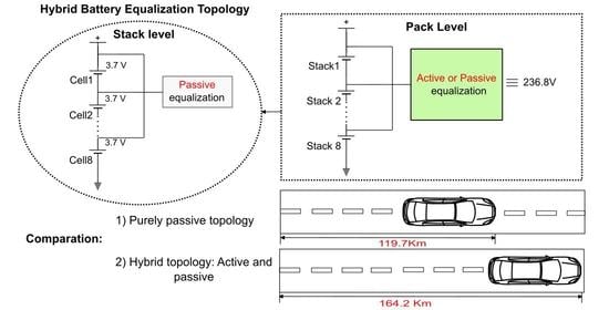
In this article, the proposal is to implement at the simulation level in Matlab and Simulink a hybrid equalization topology to simultaneously equalize the voltage difference between the stack and module. The passive technique is through energy dissipative resistors, and the active technique is through multiple inductors. For this, a package of 64 cells connected in series is assembled. The pack is divided into eight piles. Each stack has eight cells. To simulate a voltage imbalance condition, some cells were fitted with different SOC values. To correct the values and compare the equalization time and the state of charge (SOC) level, a purely passive and active topology and a combination of these two techniques are applied, running simultaneously at the stack and module levels. Subsequently, equalization techniques are applied in an EV model to assess autonomy in an FTP75 driving cycle. The values for implementing this topology are also discussed. This study corroborates to evaluate the feasibility of combining these techniques to develop a BMS system with fast equalization time and less energy loss that can be applied in projects with cost restrictions and spatial dimensions.

2. Battery Equalization

This section describes in detail the passive, active, and hybrid equalization topology and the electric vehicle (EV) model used to compare the autonomy of the topologies. In Section 2.1, the passive equalization topology is presented. In Section 2.2, the active equalization method is shown. In Section 2.3, the hybrid equalization topology is presented and the electric vehicle model is presented. It is important to note that in this work, the thermal effects are neglected, and only the operation of the circuit for energy transfer between cells and stacks is prioritized.

2.1. Passive Equalization Method

The passive equalization topology is used in a wide range of different battery management applications. The advantage of the technique lies in the simplicity of the components and control logic. Figure 1 shows a diagram of the passive topology used in simulations in the Simulink environment. The topology is composed of resistors, switches, and a control logic [2,20]. Basically, an algorithm checks the SOC of each cell, and for example, if only cell 2 has a SOC lower than 100%, the energy of the other cells will be dissipated until reaching the energy corresponding to cell 2. The energy dissipated in the resistors shunt can be estimated by Joule’s law, as described in Equation (1):
Q d i s s i p a t i o n = I b a l a n c e 2 R ,
where Q d i s s i p a t i o n is the dissipative power, imbalance is the bypass current through the shunt resistor, and R is the resistance of the shunt resistor.
For the passive equalization simulation, eight cells connected in series were used. In parallel with the cells, eight resistors of 1 ohm are connected to dissipate energy. The control is done through an algorithm that reads the state of charge value of each battery and compares the values. The state of charge values used for passive equalization is described in Table 1. Values were randomly selected to represent a voltage difference between cells.
The battery data used for all tests were based on NCM (cobalt nickel and manganese) prismatic cells manufactured by the company Sunwoda. Each cell is tuned with a nominal voltage of 3.7 V, a capacity of 106 Ah, and an average internal resistance of 0.0013 ohms.

2.2. Active Equalization Topology

This topology is reproduced from [15]; in the article, the authors used capacitors to represent battery cells. In this work, the Simulink battery blocks were used. During simulation, inductors and MOSFETs are considered ideal devices while ignoring the effects of parasitic capacitances and parasitic inductances [21,22]. As shown in Figure 2, the circuit consists of 8 cells connected in series, 7 inductors with the value of 1 Henry, and 15 MOSFETs/switches. The control is done by a PWM, with a frequency of 50 Hz and an amplitude of 3 V. The operation can be described in two stages of circuit operation: (i) in the first stage, switches S1 to S7 are turned on to store energy in the inductors. At this time, switches S8 to S14 are kept off. Still, in this step, the energy from cells 1, 2, and 3 is transferred to inductors L1 to L7. Equation (2) generally represents the equation for calculating the voltage across inductor L1 to L7.
V L k = L k di Lk d t = V C e l l n
where k represents inductor 1, 2, 3, or 4 and n represents cell 1, 3, 5, or 7.
Equations (3) and (4) describe the equation to calculate the voltage value across inductors L5 and L6:
V L 5 = L 5 di L 5 d t = V c e l l 1 + V c e l l 2
V L 6 = L 6 di L 6 d t = V c e l l 5 + V c e l l 6
Equation (5) describes the calculation for inductor L7 voltage:
V L 7 = L 7 di L 7 d t = V c e l l 1 + V c e l l 2 + V c e l l 3 + V c e l l 4
(ii) In the second stage of operation, switches S1 to S7 are turned off, and switches S8 to S14 are activated. At this time, the energy stored in the inductors is transferred to the cell. Equation (6) represents the energy from inductor L1 being transferred to cell 2:
V L 1 = L 1 di L 1 d t = V c e l l 2
Similarly, for inductors L2 to L4:
V L k = L k di Lk d t = V c e l l n
where k = 2, 3, or 4 and n = 4, 6, or 8.
The voltage of inductors L5 and L6 can be calculated, respectively, by Equations (8) and (9):
V L 5 = L 5 di L 5 d t = V c e l l 3 V c e l l 4 ,
V L 6 = L 6 di L 6 d t = V c e l l 7 V c e l l 8 .
Equation (10) represents the calculation for voltage of inductor L7:
V L 7 = L 7 di L 7 d t = V c e l l 5 V c e l l 6 V c e l l 7 V c e l l 8
The voltage and state of charge values used for the active equalization simulations are the same as those described in Table 1.

2.3. Hybrid Equalization Topology

The hybrid topology is shown in Figure 3. The pack proposed in this work contains 64 cells connected in series. Each cell has a rated voltage of 3.7 V and the total pack voltage is 236.8 V. The modules are divided into eight stacks. Each stack (Level1) contains eight cells connected in series. The voltage difference between cells can be adjusted with passive or active balancing. The voltage difference between the stacks (Level2) can also be adjusted through passive or active equalization. Thus, this work simulates the following equalization conditions: (i) active equalization between stack and passive cell levels; (ii) passive equalization between stack and active cell levels; (iii) passive equalization between stack and passive cell levels; (iv) active equalization between stack and active cell levels.
For the simulations, the initial values of the cells are different, as shown in Table 1. It is important to note that for the pack simulations, only Stack 1 has cells with different voltages. The other stacks have an initial charge state of 100%. The values were adjusted randomly and could be added to all stacks. However, it would increase the processing time for the simulations, and summarizing for just one stack, it is possible to evaluate the energy transfer between the stack and the cell level. Table 2 presents the values defined for the pack tests.
To validate the topologies proposed in this work, an electric vehicle model is used for running tests in an urban driving cycle. The model was developed by the author Isaac Ito and made available on MathWorks [10]. The model is developed in Simscape, and its components are an engine, high voltage battery, and longitudinal vehicle. In an attempt to validate the tests developed, the block of high voltage batteries is changed. Instead, the pack developed for purely passive, active, and hybrid topology is added. The conduction cycle chosen is FTP75, European standard [23], shown in Figure 4.

3. Results and Discussions

This section presents the results and discussions of simulations in the Simulink environment. Section 3.1 presents the results of passive and active equalization at the cell level. Section 3.2 presents the results of equalization by hybrid topology. Section 3.3 presents the results of hybrid equalization for an electric vehicle model with an urban driving cycle.

3.1. Passive and Active Cell-Level Equalization

For the passive and active equalization simulations, the initial values of the cells were considered different to represent a state of disequilibrium between the cells. The values are described in Table 1 (Section 2.1). Figure 5 presents the result of passive equalization at the cell level. The control algorithm identifies the value of the smallest cell and dissipates the energy of the other cells until reaching the value of cell 8, which is the smallest in relation to the other cells. The equalization time is approximately 8 h 10 min, and the balanced state of charge is approximately 74%. The passive equalization current between the cells is approximately 3.8 A. The current value is within the cell operating range of 106 Ah.
Figure 6 shows the result of active equalization. The energy from cells with higher voltage is transferred to cells with lower voltage until reaching an equilibrium point. The equalization time is approximately 3 h 33 min, with an average state of charge of approximately 85%. The active equalization current is approximately 20 to −30 A. This value is within the cell operating condition of 106 Ah. From these results, the active method has a better response time for equalization and lower energy loss compared to the passive method. This condition will reflect on the lifespan of the cells because the less energy is dissipated, the longer the lifespan of the cells. In addition, the heat dissipation of the active method will be lowered, which contributes to a better thermal management performance of a battery pack [24,25].
The current value can be limited according to the cell operating characteristics. In the simulations of this work, no current control was implemented. If the current value is limited, the equalization time increases. However, the energy transfer efficiency does not change.

3.2. Hybrid Equalization

In the battery pack proposed in this article, sixty-four cells are divided into eight modules. Each module has eight cells controlled by a passive or active equalization method. The total voltage of each module will be different due to different load conditions between the cells. In this way, it is important to adjust the voltage value between the modules. Thus, a study of different combinations of equalization at module and cell level is presented to verify which equalization method presents better time and SOC performance. The combinations are active at the module level and active at the cell level, passive at the module level and passive at the cell level, hybrid passive at the module level and active at the cell level, and hybrid active at the module level and passive at the cell level. The initial charge state values are shown in Section 2.3, Table 2.
Figure 7 shows the active equalization at the stack level and active at the module level. The equalization between the stacks takes place in approximately 2 h and at the cell level with a time of 4 h 40 min. The difference between the equalization times may be related to the voltage imbalance; in Stack 1 all cells have a voltage difference, which takes longer to balance. Analyzing the voltage difference between the stacks, only Stack 1 has a lower voltage than the others; consequently, the equalization time is shorter.
Figure 8 shows passive equalization at the stack level and passive at the cell level. The equalization time between stacks is approximately 3 h, and the state of charge is 74%. At the cell level, equalization takes approximately 8 h 10 min. Compared with the purely active method shown in Figure 7, the state of charge is 24% lower, and so this difference will impact the battery pack autonomy, heat generated by energy dissipation, and battery life.
The purely active method for balancing is the most efficient, though it is not always feasible to use in battery packs, as an example in projects where there are physical space limitations. An alternative is the hybrid equalization topology.
Figure 9 shows the result of a hybrid simulation for passive equalization between stacks and active at the cell level. The stack equalization time is approximately 1 h 30 min, with a SOC of 85%. Active cell equalization has a time of approximately 4 h and a SOC of 85%. Finally, another hybrid equalization method is simulated, active equalization between stacks and passive equalization at the module level, Figure 10 shows the results. The equalization time between stacks is 3 h and at cell level 7 h 10 min. The SOC is 96%. Compared with the method presented in Figure 9, the equalization time is longer, but the state of charge is 2% less than the purely active method.
Table 3 summarizes the comparison of all the methods simulated in this work. The hybrid active equalization method between stacks and passive at module level presents a 96% SOC, 2% smaller than the value of SOC of the purely active method. Secondly, the hybrid passive method between stacks and active at the cell level presents an SOC of 85% and satisfactory response time when compared to the purely active method. The disadvantage of applying this method in practice is that the active topology has a more significant number of electronic components, which requires the use of greater physical space in the battery pack.
Based on the results obtained in the simulations, the use of two different equalization topologies, passive and active, can be used in practice in projects with restrictions on the volume available in the battery pack casing. For example, in the configuration of the simulated pack in this work, which was based on an actual research and development project at the Federal University of Technology—Paraná, the sixty-four cells in series are divided into eight stacks. To apply a purely active topology, the number of electronic components is significant, such as inductors, MOSFETs, and control circuits. In this way, it would not be possible to develop eight slave modules for each stack, because the physical space available in the casing is restricted. The solution is to use slave modules with the passive equalization technique. An example of a compact commercial integrated circuit is the BQ79656-Q1 from Texas Instruments. From the simulated results, applying the active topology only to equalize the voltage difference between the stacks, the energy efficiency is significant when compared to a purely passive technique, and also satisfactory when compared to a purely active technique.
The cost for the construction of the hybrid topology, considering the main components of power electronics, and based on reference to the market values consulted in September 2022, the approximate total value for the development of the hybrid system is shown in Table 4 when active at stack level and passive at the module level. This value can be more expensive as it involves two equalization topology techniques. However, considering the energy efficiency advantages, the value is satisfactory when compared to a purely active technique.

3.3. Hybrid EQ Applied to an EV

Simulations with the EV model are essential to validate the different combinations of the proposed topology and evaluate the autonomy. Based on the results presented in Section 3.1, two combinations were chosen to test in the EV model: purely passive and hybrid active between stacks and passive at the cell level. The parameters used in the simulations are presented in Table 3, Section 2.3.
Figure 11 and Figure 12 present the results of the purely passive topology implemented in the EV. The FTP75 drive cycle is repeated until the battery is fully discharged. Figure 11 shows in detail the driving cycle (km/h), the total pack voltage (V), the state of charge (%), and the pack current (A).
Figure 12 presents in detail the voltage and SOC between the eight stacks and the voltage and SOC at the cell level of Stack 1, where it is possible to verify the equalization between stacks with the passive equalization occurring in approximately 2000 s. Passive cell-level equalization does not happen at this time. The passive equalization time is around 28,800 s, as shown in Section 3.1. Each driving cycle has 2474 s. For this simulation with purely passive topology, it was possible to perform almost seven complete cycles (16,980 s). With an average speed equal to 34.1 km/h, it is possible to cover a distance of 119.7 km.
Figure 13 and Figure 14 present the results of the hybrid equalization methodology, active between stacks and passive at the cell level (Stack 1). Figure 13 shows in detail the speed (km/h) during the driving cycle, the voltage (V) of the battery pack, SOC (%), and current (A) of the pack.
Figure 14 presents in detail the voltage (V) and SOC (%) between the stacks and Stack 1. In this configuration, the distance traveled was 164.2 km, 44.5 km more than the purely passive topology. In this way, this combination is an alternative to increase the autonomy of a battery pack by adding an active equalization topology only between the stacks of the pack. It is important to point out that the pack current was not controlled, and at the end, when the voltage is reduced, the current is above 106 Ah. This value can be controlled and, in practice, will decrease the EQ speed. Energy efficiency is not affected in this case.

4. Conclusions

BMSs are responsible for managing an EV batteries. From the voltage, current, and temperature readings, several parameters are controlled to maintain the correct functioning of the pack. The equalization of voltage between the cells is one of the fundamental parameters for the useful life of the batteries, in addition to adequate charge control to guarantee the autonomy of the EV. There are two main cell EQ methods: passive and active. This article collaborates in the study of the combination of these two techniques to evaluate the autonomy of a pack in a driving cycle.
Based on simulated results, the hybrid EQ technique, active between stacks and passive at the cell level, has a range of 44.5 km more than the purely passive topology. In this topology configuration, the active equalization circuit is added only to transfer energy between the stacks. At the cell level, a passive equalization circuit is applied. Therefore, the proposal of the hybrid topology presented and simulated in this article is promising for applications in electric vehicles, since it is possible to build printed circuit boards (PCBs) with dimensions in the order of prismatic cells, simplify the management of control circuits and obtain higher energy yield when compared to purely passive techniques. It is essential to highlight that in this article that active EQ is based on a circuit of multiple inductors, other types of circuits can also be applied, such as circuits based on capacitors, and converters, among others that can present a better performance equalization time.

Author Contributions

Conceptualization, J.R.G., F.C.C. and P.B.J.; methodology, J.R.G., F.C.C. and P.B.J.; simulation, J.R.G.; formal analysis, J.R.G., F.C.C. and P.B.J.; schematic drawings, J.R.G. and K.M.d.S.; writing—original draft preparation, J.R.G., F.C.C., J.D.G., P.B.J. and L.B.C.; supervision, F.C.C. All authors have read and agreed to the published version of the manuscript.

Funding

This research was funded by Rota 2030 Public Call 01/2020, Agreement 27192.03.01/2020.16-00 and the APC was funded by Coordination for the Improvement of Higher Education Personnel (CAPES) Financing Code 001.

Acknowledgments

The authors thank Foundation for Research Development—FUNDEP—Rota 2030, Public Call 01/2020, Agreement 27192.03.01/2020.16-00, for their financial support.

Conflicts of Interest

The authors declare no conflict of interest.

References

  1. Ramkumar, M.S.; Reddy, C.; Ramakrishnan, A.; Raja, K.; Pushpa, S.; Jose, S.; Jayakumar, M. Review on Li-Ion Battery with Battery Management System in Electrical Vehicle. Adv. Mater. Sci. Eng. 2022, 2022, 3379574. [Google Scholar] [CrossRef]
  2. Daowd, M.; Antoine, M.; Omar, N.; Lataire, P.; Van Den Bossche, P.; Van Mierlo, J. Battery management system—Balancing modularization based on a single switched capacitor and bi-directional DC/DC converter with the auxiliary battery. Energies 2014, 7, 2897–2937. [Google Scholar] [CrossRef] [Green Version]
  3. Daowd, M.; Omar, N.; Van Den Bossche, P.; Van Mierlo, J. Passive and active battery balancing comparison based on MATLAB simulation. In Proceedings of the 2011 IEEE Vehicle Power and Propulsion Conference, Chicago, IL, USA, 6–9 September 2011; pp. 1–7. [Google Scholar]
  4. Ouyang, D.; Chen, M.; Liu, J.; Wei, R.; Weng, J.; Wang, J. Investigation of a commercial lithium-ion battery under overcharge/over-discharge failure conditions. RSC Adv. 2018, 8, 33414–33424. [Google Scholar] [CrossRef] [Green Version]
  5. Hu, X.; Zhang, K.; Liu, K.; Lin, X.; Dey, S.; Onori, S. Advanced Fault Diagnosis for Lithium-Ion Battery Systems: A Review of Fault Mechanisms, Fault Features, and Diagnosis Procedures. IEEE Ind. Electron. Mag. 2020, 14, 65–91. [Google Scholar] [CrossRef]
  6. Barreras, J.V.; Pinto, C.; de Castro, R.; Schaltz, E.; Andreasen, S.J.; Araújo, R.E. Multi-objective control of balancing systems for li-ion battery packs: A paradigm shift? In Proceedings of the 2014 IEEE Vehicle Power and Propulsion Conference (VPPC), Coimbra, Portugal, 27–30 October 2014; pp. 1–7. [Google Scholar]
  7. Gallardo-Lozano, J.; Romero-Cadaval, E.; Milanes-Montero, M.I.; Guerrero-Martinez, M.A. Battery equalization active methods. J. Power Sources 2014, 246, 934–949. [Google Scholar] [CrossRef]
  8. Ganesha, N.; Yadav, G.; Gowrishankara, C. Analysis and Implementation of Inductor Based Active Battery Cell Balancing Topology. In Proceedings of the 2020 IEEE International Conference on Power Electronics, Drives and Energy Systems (PEDES), Jaipur, India, 16–19 December 2020; pp. 1–6. [Google Scholar]
  9. Farzan Moghaddam, A.; Van den Bossche, A. A Ćuk converter cell balancing technique by using coupled inductors for lithium-based batteries. Energies 2019, 12, 2881. [Google Scholar] [CrossRef] [Green Version]
  10. Battery Electric Vehicle Model in Simscape. Available online: https://www.mathworks.com/matlabcentral/fileexchange/82250-battery-electric-vehicle-model-in-simscape?s_tid=srchtitle (accessed on 10 July 2022).
  11. De Alcântara Dias, B.M.; da Silva, C.T.; Araújo, R.E.; de Castro, R.; Pellini, E.L.; Pinto, C.; Laganá, A.A.M. An Analytic Hierarchy Process for Selecting Battery Equalization Methods. Energies 2022, 15, 2439. [Google Scholar] [CrossRef]
  12. Koseoglou, M.; Tsioumas, E.; Jabbour, N.; Mademlis, C. Highly effective cell equalization in a lithium-ion battery management system. IEEE Trans. Power Electron. 2019, 35, 2088–2099. [Google Scholar] [CrossRef]
  13. Alvarez-Diazcomas, A.; Estévez-Bén, A.A.; Rodríguez-Reséndiz, J.; Martínez-Prado, M.A.; Carrillo-Serrano, R.V.; Thenozhi, S. A review of battery equalizer circuits for electric vehicle applications. Energies 2020, 13, 5688. [Google Scholar] [CrossRef]
  14. Angkititrakul, S.; Hu, H.; Liang, Z. Active inductor current balancing for interleaving multi-phase buck-boost converter. In Proceedings of the 2009 Twenty-Fourth Annual IEEE Applied Power Electronics Conference and Exposition, Washington, DC, USA, 15–19 February 2009; pp. 527–532. [Google Scholar]
  15. Moghaddam, A.F.; Van Den Bossche, A. An active cell equalization technique for lithium ion batteries based on inductor balancing. In Proceedings of the 2018 9th International Conference on Mechanical and Aerospace Engineering (ICMAE), Budapest, Hungary, 10–13 July 2018; pp. 274–278. [Google Scholar]
  16. Xu, P.; Kang, L.; Xie, D.; Luo, X.; Lin, H. A Switch-Reduced Multicell-to-Multicell Battery Equalizer Based on Full-Bridge Bipolar-Resonant LC Converter. Batteries 2022, 8, 53. [Google Scholar] [CrossRef]
  17. Lu, C.; Kang, L.; Wang, S.; Wang, Z.; Rao, H. A Novel Inductor-Based Non-Dissipative Equalizer. Energies 2018, 11, 2816. [Google Scholar] [CrossRef] [Green Version]
  18. Fang, L.; Li, J.q.; Shi, W. Design and implementation of the state monitoring and balancing management of vehicle power battery. Energy Procedia 2017, 105, 2725–2732. [Google Scholar] [CrossRef]
  19. Zhang, Z.; Gui, H.; Gu, D.J.; Yang, Y.; Ren, X. A hierarchical active balancing architecture for lithium-ion batteries. IEEE Trans. Power Electron. 2016, 32, 2757–2768. [Google Scholar] [CrossRef]
  20. Hua, Y.; Zhou, S.; Cui, H.; Liu, X.; Zhang, C.; Xu, X.; Ling, H.; Yang, S. A comprehensive review on inconsistency and equalization technology of lithium-ion battery for electric vehicles. Int. J. Energy Res. 2020, 44, 11059–11087. [Google Scholar] [CrossRef]
  21. Liu, K.; Yang, Z.; Tang, X.; Cao, W. Automotive battery equalizers based on joint switched-capacitor and buck-boost converters. IEEE Trans. Veh. Technol. 2020, 69, 12716–12724. [Google Scholar] [CrossRef]
  22. Tseng, K.C.; Huang, H.S.; Cheng, C.A. A Power Conversion Technique with Hierarchical Equalization Charging Topology for LiFePO4 Batteries. Micromachines 2021, 12, 1014. [Google Scholar] [CrossRef]
  23. Drive Cycle Source FTP75. Available online: https://www.mathworks.com/help/autoblks/ref/drivecyclesource.html (accessed on 1 July 2022).
  24. Zhong, H.; Lei, F.; Zhu, W.; Zhang, Z. An operation efficacy-oriented predictive control management for power-redistributable lithium-ion battery pack. Energy 2022, 251, 123851. [Google Scholar] [CrossRef]
  25. Lee, S.W.; Lee, K.M.; Choi, Y.G.; Kang, B. Modularized design of active charge equalizer for Li-ion battery pack. IEEE Trans. Ind. Electron. 2018, 65, 8697–8706. [Google Scholar] [CrossRef]
Figure 1. Schematic drawing of passive equalization.
Batteries 08 00178 g001
Figure 2. (a) Schematic diagram of the multiple inductor circuit. (b) The first stage of circuit operation closes switches S1 to S7. (c) The second stage of circuit operation closes switches S8 to S14.
Batteries 08 00178 g002
Figure 3. Schematic diagram of hybrid equalization topology.
Batteries 08 00178 g003
Figure 4. FTP75 driving cycle used in the simulations.
Batteries 08 00178 g004
Figure 5. Passive cell-level equalization.
Batteries 08 00178 g005
Figure 6. Active cell-level equalization.
Batteries 08 00178 g006
Figure 7. Active equalization at stack and cell levels.
Batteries 08 00178 g007
Figure 8. Passive equalization at stack and cell levels.
Batteries 08 00178 g008
Figure 9. Passive stack-level and active cell-level hybrid equalization.
Batteries 08 00178 g009
Figure 10. Hybrid equalization: active stack level and passive cell level.
Batteries 08 00178 g010
Figure 11. Simulation results of the EV model. The driving cycle is repeated until the battery pack is fully discharged. The equalization of stacks and cells is done by the passive method.
Batteries 08 00178 g011
Figure 12. Simulation results of the EV model. Details of voltage and SOC behavior of passive equalization at stack and cell levels.
Batteries 08 00178 g012
Figure 13. EV model simulation results. The driving cycle is repeated until the battery is fully discharged. EQ is active across stacks and passive at the cell level.
Batteries 08 00178 g013
Figure 14. Simulation results of the EV model. Details of voltage and SOC behavior of passive equalization at stack and cell levels.
Batteries 08 00178 g014
Table 1. Initial parameters for simulating the passive equalization topology.
CellVoltage (V)Initial Charge State (%)
13.7100
23.6999.73
33.3891.35
43.4593.24
53.4192.16
63.5295.13
73.5896.75
83.3791.08
Table 2. Initial charge state values used in battery pack simulations.
StackStack Voltage (V)Initial Charge State (%)
128.2Cell 1 = 100; Cell 2 = 99.73; Cell 3 = 91.35; Cell 4 = 93.24; Cell 5 = 92.16; Cell 6 = 95.13; Cell 7 = 96.75, and Cell 8 = 91.8;
2, 3, 4, 5, 6, 7, and 829.6100
Table 3. Comparison of equalization topologies.
TopologyEqualization TimeSOC—Stack (%)SOC—Cell (%)
Active cell-level balancing3 h 33 min-85
Cell-level passive balancing8 h 10 min-74
Active stack-level and cell-level active balancing2 h (stack) 4 h 40 min (cell)9898
Passive stack-level and cell-level passive balancing3 h (stack) 8 h 10 min (cell)7474
Active stack-level and cell-level passive hybrid balancing3 h (stack) 7 h 10 min (cell)9696
Passive stack-level and active cell-level hybrid balancing1 h 30 min (stack) 4 h (cell)8585
Table 4. Approximate cost for building the hybrid topology to be active at the stack level and passive at the cell level.
TopologyComponentsValue (USD)
One module-level active topology14 Mosfets, 7 inductors, and a control circuit300.00
Eight passive topology slave modulesFront-end integrated circuit, power resistors, voltage, current, and temperature instrumentation2000.00
Total cost = 2300.00
Publisher’s Note: MDPI stays neutral with regard to jurisdictional claims in published maps and institutional affiliations.

