
Smart Battery Technology for Lifetime Improvement
by
 , ,
, ,
Remus Teodorescu
1,
Xin Sui
1,* ,
,
Søren B. Vilsen
2,
Pallavi Bharadwaj
1,
Abhijit Kulkarni
1 and
Daniel-Ioan Stroe
1
1
AAU Energy, Aalborg University, 9220 Aalborg, Denmark
2
Department of Mathematical Sciences, Aalborg University, 9220 Aalborg, Denmark
*
Author to whom correspondence should be addressed.
Batteries 2022, 8(10), 169; https://doi.org/10.3390/batteries8100169
Submission received: 26 August 2022
/
Revised: 26 September 2022
/
Accepted: 30 September 2022
/
Published: 9 October 2022
(This article belongs to the Special Issue Artificial Intelligence-Based State-of-Health Estimation of Lithium-Ion Batteries)
Abstract
:Applications of lithium-ion batteries are widespread, ranging from electric vehicles to energy storage systems. In spite of nearly meeting the target in terms of energy density and cost, enhanced safety, lifetime, and second-life applications, there remain challenges. As a result of the difference between the electric characteristics of the cells, the degradation process is accelerated for battery packs containing many cells. The development of new generation battery solutions for transportation and grid storage with improved performance is the goal of this paper, which introduces the novel concept of Smart Battery that brings together batteries with advanced power electronics and artificial intelligence (AI). The key feature is a bypass device attached to each cell that can insert relaxation time to individual cell operation with minimal effect on the load. An advanced AI-based performance optimizer is trained to recognize early signs of accelerated degradation modes and to decide upon the optimal insertion of relaxation time. The resulting pulsed current operation has been proven to extend lifetime by up to 80% in laboratory aging conditions. The Smart Battery unique architecture uses a digital twin to accelerate the training of performance optimizers and predict failures. The Smart Battery technology is a new technology currently at the proof-of-concept stage.
1. Introduction
Due to their high power density (≈1500 W/kg) and energy density (≈250 Wh/kg), high energy efficiency (>95%), and also relatively long cycle life measured in thousands of cycles, Li-ion batteries are the accepted solution for electronics, transportation, and grid storage. Battery packs are composed of a string of series and parallel connected cells to meet the power requirements of the applications. Cells cannot be manufactured with identical electrical characteristics, and these differences get amplified during operation, leading to a large unbalance in state of health (SOH) and premature lifetime termination. Therefore, it is essential to find a strategy that is able to operate with cells having unequal characteristics without limitation in performance. For achieving this goal, the concept of Smart Battery technology is proposed in this paper, using power electronics for the bypass device and artificial intelligence for performance optimization.
In the first stage, we explored several pulsed current charging strategies and their effect on battery lifetime. As shown in Figure 1, an up to 80% lifetime extension can be achieved by charging with a 2C-rate, 50% duty cycle, and 0.05 Hz current in comparison with a 1C-rate constant current with equivalent average charging power. It is generally believed that the pulsed current favorable effect is due to the slowing down of the degradation modes associated with high C rate operation over long periods, such as loss of active material. In addition, a Smart Battery lifetime prediction framework is proposed, as described in Section 4. Under the framework, the short-term (daily or weekly) state of health (SOH) can be accurately estimated based on a partial charging curve. With the help of the short-term SOH estimates, the established model is updated by transfer learning to track the long-term degradation behavior of batteries under varied working conditions.
The structure of the paper includes the hardware architecture and realization of the bypass device and cell controller with wireless communication, State of Temperature (SOT), SOH estimation and prediction, and Digital Twin as tools to improve safety and performance followed by a conceptual approach of the complex performance optimization problem definition. In the end, applications of the Smart Battery are identified.
2. The Hardware Architecture
The Smart Battery system aims to develop an integrated battery solution with increased safety, fault-tolerant operation, improved lifetime, and software reconfiguration for second life applications. The high-level architecture of a Smart Battery system is shown in Figure 2 and consists of a cell connected to a half-bridge circuit, which is controlled by a digital controller termed a slave CPU. The cell is connected to the battery string via the output ports of the half-bridge, as shown in Figure 2. The switching state of the half-bridge determines if the cell is inserted into the string or bypassed. Figure 3a,b show the state of the output terminals of the half-bridge when the cell is inserted or bypassed, respectively. By turning on the top device the cell will be inserted, and by turning on the bottom device, the cell will be bypassed. Note that the two devices are switched in complimentary PWM and can be switched at any frequency and duty ratio to realize pulsed charging or discharging of the cell. The slave controller provides the switching commands to the half-bridge, and monitors the cell voltage, current, and temperature using the appropriate sensors. Using the measurements, the slave estimates the state of charge (SOC) and communicates the measurements to the master controller shown in Figure 2. Note that the master controller (shown as master CPU/GPU in Figure 2) uses AI-based algorithms to estimate the state of health (SOH) and remaining useful life (RUL) for the cells and communicates the same information to respective cells. The master controller performs the functions of SOC and SOH balancing and lifetime control. The balancing process is done by bypassing one cell at a time and thus not affecting the load current. In contrast to other active balancing methods, this balancing method does not use bidirectional DC–DC converters. It has better efficiency due to the absence of additional inductors/capacitors used in active balancing methods. The proposed bypass device only needs to order the cells according to their SOC and SOH states and then decides which cell should be bypassed. The method for balancing control is simple and effective. This provides a fault-tolerant operation mode, which can improve the safety and reliability at the system level.
2.1. Smart Battery Cell—Hardware Implementation Approach
Individual cells are integrated with a half-bridge circuit to provide the bypass capability as described above. The overall control electronics consist of the following subgroups:
- MOSFETs: Low on-resistance MOSFETs are used in the half-bridge across the cell. It is important to have low-on resistance to limit the power loss in the MOSFETs, which acts as an undesirable load on the batteries. Note that MOSFETs with sub-milliohm on-resistances () are available and they introduce negligible losses. It is also possible to parallel additional MOSFETs to reduce the resistance further and to provide redundancy for improving the reliability. Table 1 shows some of the commercially available MOSFETs with sub-milliohm and conduction loss at 50 A. It would be good to use automotive-certified MOSFETs (e.g., AUIRF8739L2TR [2] in Table 1) such as electric vehicles (EVs) is one of the major applications for the Smart Battery.
- Sensors: To monitor the cell voltage, current, and temperature, appropriate sensors are used. Additional electronic circuits are essential to interface the sensors with the slave controller. The sensors can be interfaced with the analog-to-digital converter (ADC) channels of the controller or to the appropriate digital communication channels depending on the output format.
- Voltage regulators: Switching voltage regulators are necessary to convert the battery voltage to the required regulated DC voltage to supply the control electronics and to the gate drivers of the half-bridge circuit. Note that linear regulators cannot be used because typically they can only step down the cell voltage and they have poor efficiency.
- Gate driver: A smart gate driver is necessary to implement the insert/bypass functionality of the Smart Battery. This gate driver receives the commands from the slave controller, which in turn obtains the commands from the master controller wirelessly. The gate driver will also prevent any shoot through of the DC voltage, hence avoiding any short circuit.
- Slave controller: The slave controller performs the computation of SOC, provides commands to the gate driver, implements protection algorithms, and communicates with the master wirelessly. For wireless communication, protocols such as wifi, Bluetooth Low Energy (BLE), and Zigbee are possible. The range required for the wireless communication for the Smart Battery is in the order of a few meters considering the application area of electric vehicles, wherein the Smart Battery will be tightly packed and the master controller will be at close proximity within the vehicle. Considering these points, BLE communication can be one of the options. However, since the Smart Battery architecture for EV involves a large number of slaves (>100), custom wireless protocols such as IEEE TSCH may be a good compromise between performance and power consumption. Texas Instruments offers a number of wireless controllers suitable for BMS applications. One popular series is the Simplelink controller CC26 × 2 [3,4].
2.2. Layout Design for Low Electromagnetic Interference (EMI)
Figure 4 shows the detailed components of the single cell in the Smart Battery architecture and its hardware components described above. The electronic circuits in Figure 4 contain EMI sources as well as sensitive electronics whose performance may be impacted by the EMI. For example, the switching regulators to supply regulated voltage produce both conducted and radiated noise. As these converters are switched at a high frequency in the order of a few MHz, the radiated noise may interfere with the BLE communication. Thus, it is important to protect the communication and the sensing circuits from the noise generated by the switching regulators. Note that the switching by the MOSFETs of the half-bridge may not result in any appreciable EMI because these MOSFETs are switched at a very low frequency in the order of a few hertz or less. As a result, this switching does not radiate any significant energy at the BLE frequencies of interest and can be ignored as the source of conducted or radiated EMI.
In order to minimize the impact of EMI and ensure high fidelity communication, a multi-layer routing is followed for the printed circuit board (PCB) to provide good ground planes and to minimize the loop areas that can cause unwanted radiation [5]. The components of the switching regulators are physically placed in a predefined area and they are covered by an EMI shield. This ensures that the BLE communication is not impacted by the radiations from the switching regulators. A green border shown around the DC–DC converter in Figure 4 illustrates the EMI shield across it. As the Smart Battery cells are in close physical proximity in applications such as EV battery packs, a proper layout design prevents noise from one PCB from impacting the communication with the neighboring PCBs and with the master controller.
2.3. Hardware Challenges and Design for High Current
For cells with high Ah capacity such as 50 Ah or more, the design of the slave board is to be done to minimize the losses and impact of parasitics such as stray inductances. The current in such cells can be hundreds of amperes for any operation beyond 2C. Thus, the hardware design needs to provide a low resistance path for the current and low conduction loss in the MOSFETs. A conceptual diagram illustrating the slave board design for a prismatic cell is shown in Figure 5. A combination of copper bus bars and copper in-lays is used, as shown in Figure 5 (shown in orange) to provide a low resistance path for the high current. The half-bridge is shown with two MOSFETs, Q1 and Q2. Note that a parallel combination of multiple MOSFETs may be necessary to minimize the losses. The bus bar design should also ensure that parasitic inductances are very low as they can cause large voltage spikes on the MOSFETs during insert/bypass operations.
3. SOT Estimation
Li-ion batteries, due to their high energy/power density, long cycle life, and high efficiency, have been widely used in electric vehicles, portable electronics, and smart grid systems. However, thermal-related technological bottlenecks, including thermal runaway [6], extreme fast charging (XFC) [7,8], reduced performance in cold climates [9,10], and accelerated aging at high temperatures [11,12], still hinder the large-scale application of Li-ion batteries. Such bottlenecks stem from the complex effect of temperature on the safety, performance, and lifespan of Li-ion batteries. For instance, when battery temperature exceeds the threshold under extreme situations, thermal runaway might be triggered and accompanied by safety problems such as smoke, fire, and explosion [6]. In cold climates, the performance of Li-ion batteries is severely reduced due to slow electrochemical reactions inside the cell [10,13], and thus the available energy and power of Li-ion batteries decline dramatically [9,10]. Additionally, XFC at relatively lower temperatures is likely to trigger lithium plating, which leads to accelerated battery degradation [11,12]. At elevated temperatures, side reactions such as the growth of a solid electrolyte interface become significant, giving rise to the consumption of cyclable lithium and accelerated battery capacity fade [8,12].
Battery management systems (BMS) are indispensable for managing the charging/discharging patterns and regulating battery temperature in a smart way, where temperature monitoring serves as the basis of the BMS. Typically, battery temperature can be monitored by temperature sensors placed on the battery surface. However, in real-life battery packs, it is impractical to place temperature sensors on the surface of each battery cell due to cost and complexity considerations. Furthermore, the surface-mounted sensors cannot track the rapid variation of internal temperatures because of heat transfer delay from the battery core to the surface caused by the thermal mass of the battery, especially at high charging/discharging rates. Hence, it is of great significance to estimate the battery temperature in a battery pack, and accurate SOT estimation benefits battery management in several ways.
From the perspective of battery safety, accurate monitoring of internal temperature helps keep the battery within the safety threshold and gives an early warning of potential hazards that could trigger thermal runaway. In particular, nowadays, Li-ion batteries are designed to have large capacities and high power/energy densities, which could inevitably enhance the risk of thermal hazards. From the perspective of fast charging, SOT estimation helps regulate battery temperature actively to a charging favorable temperature range so that XFC can be achieved and the lifetime of the battery can also be extended [14]. From the perspective of battery health management, knowing battery SOT makes it possible to develop a temperature-independent SOH estimation by decoupling the temperature effect during the extraction of health indicators, which gives rise to a more accurate and robust SOH estimation. This will further allow for accurate lifetime prediction and improvement of the operation of the Smart Battery. All of these features of the Smart Battery enabled by accurate SOT estimation are illustrated in Figure 6.
Existing methods for SOT estimation can be classified into three categories: impedance-based estimation, thermal model-based estimation, and data-driven estimation. Impedance-based estimation exploits the relationship between battery temperature and impedance parameters such as phase, real part, and imaginary part, to estimate SOT according to the measured impedance [15]. By modeling the heat generation and heat transfer models inside the cell, thermal model-based methods realize the internal temperature estimation based on battery current, voltage, and possibly a surface-mounted sensor [16]. Data-driven approaches ignore the thermal dynamics of the cell and explore the data patterns of battery temperature evolution to realize highly accurate estimation [17]. However, these three methods have limitations. Impedance-based estimation can only provide information about the average temperature of the cell but neglect the temperature distribution inside the cell. Therefore, the maximum internal temperature is likely to be underestimated, especially for large-format cells with high energy/power density or cells operating at high rates (e.g., XFC). As for thermal model-based estimation, it is a great challenge to balance the model complexity and accuracy. In addition, parameterization is sometimes complex due to many required model parameters. For data-driven approaches, obtaining a considerable training dataset is sometimes technically challenging and unattainable. For instance, the temperature value at random points inside the cell cannot be measured. Generalization is another problem for many data-driven approaches since the training dataset cannot cover all of the operation scenarios.
To address the challenges existing SOT estimation methods face, there is a growing trend to combine model-based approaches with data-driven methods to realize accurate and robust estimation [18,19]. There are many ways to combine physics-based models and machine learning models, as discussed in [20]. A competitive candidate, which will be used in the framework of the Smart Battery, is the physics-informed neural network (PINN). PINN can rapidly solve the underlying nonlinear heat transfer partial differential equation (PDE) with small amounts of data and provide insights into battery internal temperature distribution. Typically, the temperature data used for neural network training is limited to the surface temperature and possibly the core temperature measured through sensor intrusion [21,22], making it difficult for conventional neural networks to estimate the temperature distribution between the core and the surface. PINN can overcome the limitations traditional neural networks face and mimic the data patterns governed by the heat transfer PDE so that the temperature distribution inside the cell can be estimated. The framework of a PINN for estimating the battery temperature distribution is shown in Figure 7, where a cylindrical cell is used as an example. When collecting the training data, the current, voltage, surface, and core temperature can be measured (by inserting a sensor into the battery core). The measured data are treated as training data for the deep neural network, and the loss is calculated based on the predicted temperature and the measured temperature. Additionally, the temperature at the core, the surface, and any point inside the domain should follow the heat transfer PDE and its initial and boundary conditions. The differentials of temperature with respect to time and location can be calculated through automatic differentiation so that the physics loss can be obtained accordingly based on heat transfer PDE. In PINN, the loss function consists of the loss of training data and the loss of physics. By minimizing the total loss, the weights and biases of the neural networks can be adjusted, and the unknown coefficient in the PDE can be identified. For a trained PINN, the predictions can have high accuracy while also following the heat transfer law so that it can be used to estimate internal temperature distribution under other operating conditions.
Accurate SOT estimation using PINN represents the first step toward the goal of realizing long-term (e.g., 10 min ahead) temperature prediction, which will lead to optimal operation and reduce safety concerns of the Smart Battery.
4. SOH Estimation and Lifetime Prediction
The degradation of the battery is unavoidable, and it is caused by complex aging mechanisms that are happening in parallel inside the battery. At the macroscopic scale, the degradation of the battery is manifested as capacity fade and power fade [23] that are therefore often used as indicators of a battery’s SOH. Using these two measures of degradation, a battery is considered at the end-of-life (EOL) when its capacity reaches 70–80% of the initial capacity. Given an EOL criterion, the RUL of the battery can be defined as the time (or the number of cycles) until the battery reaches its EOL [24]. It follows that to lower the cost of Li-ion batteries, both environmentally and economically, it is imperative to control their RUL [25]. Accurately predicting the RUL of the battery will also help reduce the cost through predictive maintenance, reduce the risk of failure guaranteeing safer operation, and improve the reliability of the system [25]. However, the degradation of batteries begins the moment they exit the production line, resulting in reduced lifetime. Additionally, Li-ion batteries undergo a wide range of aging conditions during real-world operations, from calendar aging (idling) to cycling aging (charging or discharging), which is non-deterministic and difficult to predict. These uncertainties create a bottleneck in the large-scale acceptance and deployment of Li-ion batteries in critical applications, such as transportation.
4.1. SOH Estimation
After a decade of research on battery SOH estimation, SOH estimation methods are slowly becoming mature [26,27,28]. SOH estimation methods typically fall into one of three categories: (1) Empirical methods, (2) physics-based models, and (3) AI data-driven methods. While empirical methods such as directly measuring the charge throughput or indirectly analyzing the incremental capacity have been used to quantify the SOH mechanisms, their stability severely limits their use in real-life applications. The physics-based models are designed to estimate the SOH through state-space models typically built using electrochemical models, or equivalent electrical circuit models [29]. The physics-based models use filters to effectively update the dynamic characteristics of the system, but are entirely dependent on the accuracy of the underlying physics-based model, which introduces an unavoidable and cumbersome parameter identification process requiring extensive laboratory testing. Lastly, recent years have seen the rise of more data-driven methods through statistics, machine learning, and artificial intelligence methods. These methods have the ability to effectively learn any non-linear regression problem, given enough of the right data. Among the most popular are methods such as support vector machine, artificial neural network, deep learning (DL), and random forest [30].
The battery degradation process is accompanied by a series of side reactions involving various parts of the battery, such as the anode, cathode, electrolyte, and electrode–electrolyte interface. As a result, the battery will exhibit different aging behaviors as the operating conditions change. This leads to the biggest challenge of data-driven methods for SOH estimation: features extracted under laboratory conditions might be invalid in real-life applications. There are three ways to account for this discrepancy: (1) To define and extract robust features, (2) to adapt models from the laboratory to the field by transfer learning, and (3) to use automatic feature extraction through DL. A viable method for creating and extracting robust features is the fuzzy entropy method as proposed in [31]. It has been shown that fuzzy entropy-based features are effective in both SOH estimation and SOH prediction. Additionally, it has been proven to have strong robustness against parameter selection, data size, working conditions, and noise [31]. Moreover, noise suppression methods were used to pre-process the SOH data, improving not just the accuracy but also the speed of the fuzzy entropy-based feature extraction [32,33]. An alternative to creating robust features is to account for the change in domain by transferring the model [34]. There are two approaches to adapting models from one domain to another—during the training of the model the discrepancy between the features in the two domains is accounted for, or the model is trained in the original domain and then re-trained in the new domain. The second approach will give better results but requires knowledge of the SOH in both domains unlike the first approach [35]. Lastly, the feature failure problem may be almost entirely avoided using DL. Deep neural networks have the ability to extract global features from raw multi-dimensional data. However, due to the latent nature of SOH, obtaining the amount of SOH information required to train such a neural network is usually impossible in real-life applications. In order to improve the estimation accuracy on small data sizes, a bagging-based ensemble method was proposed in [36]. Bagging creates augmented samples by resampling from the original dataset, and a series of ELMs are trained based on these samples. The bagging ELM method has many of the upsides of DL, such as the automatic feature extraction, while requiring much less data to train and perform well when estimating SOH. In addition to using fuzzy entropy-based features and the ensemble ELM method, the Smart Battery framework aims to increase the amount of useful information extracted from a single partial charge of the battery by data augmentation. The augmentation will allow for the extraction of not only the charging voltage, but also every partial charging voltage sequence found within any charge (no matter how large). The general framework for data cleaning, augmentation of partial charges, feature extraction, and SOH estimation is outlined in the top panel of Figure 8.
4.2. SOH and Lifetime Prediction
The aim of any RUL algorithm is to predict the time to EOL of a battery. However, before the EOL can be predicted, it is necessary to predict the SOH; given a mission profile and a short-term SOH prediction method, the long-term behavior of the SOH can be predicted to the EOL. SOH and RUL prediction methods are usually divided into physics-based and data-driven AI-based methods. In the physics-based lifetime models, while the non-linear and time-varying characteristics of the electrochemical system can be explained, the parameters of these models are very difficult to identify since they rely on destructive testing methodologies. Consequently, the development of physics-based models is time and resource-demanding, and thus not necessarily a viable option for use in real-time prediction. These methods are more suitable to study the aging mechanisms of the battery, provide a theoretical basis for data-driven methods, and make suggestions on battery design [36]. The data-driven AI-based methods used for lifetime modeling and prediction are unlike SOH estimation, and are usually more probabilistic in nature. Among the most common methods are Gaussian process regression and dynamic Bayesian networks. Their main advantage is that they do not need access to the mechanical and electrochemical behavior of the battery [37]. The disadvantage is the need to specify the structure of the probabilistic structure of these models. Therefore, recent years have seen an increase in the use of DL methods. A DL lifetime model can be established based on the collected data and continually updated using gradient optimization [38]. That is, the relationship between the features (i.e., the health indicators such as voltage, current, and temperature) and the cycle and calendar life of the battery cell can be established. The main disadvantages of DL methods are their computational cost, and that they are not probabilistic by nature, making RUL uncertainty prediction difficult.
However, as cloud computation becomes cheaper and more readily available, many DNN algorithms have shown promise, such as deep neural networks [39], convolutional neural networks [40], and recurrent neural networks (RNNs) [41]. RNN will be a suitable algorithm for RUL prediction because of its intrinsic modeling of time-dependent parameters. Furthermore, to accommodate the need for probabilistic predictions, the Smart Battery framework will attempt to combine approximate Bayesian methods, such as approximate Bayesian computation [42,43], Bayesian synthetic likelihood [44], or variational inference with RNNs.
The biggest challenge with the SOH and RUL prediction methods mentioned above is that they need SOH measurements to function. However, in real-life applications, obtaining SOH measurements means stopping the operation of the battery and running an entire cycle, i.e., fully charge and discharge the battery. Furthermore, for these prediction methods to be effective, this needs to be performed on a regular schedule, and as often as possible. As this is not a possibility in most applications, the predictions created in most applications would be extremely unreliable (i.e., the uncertainty intervals of their predictions would be large). Therefore, in the Smart Battery framework, the SOH and RUL prediction will not operate directly on the SOH, but can instead operate on the SOH estimation model, which can provide an estimate of the SOH for every partial charge of the battery. Given the estimated SOH, a post-processing may need to be applied to remove effects of dependencies such as temperature and C-rate (if this effect cannot be removed through the construction of invariant features). The use of the estimated SOH when predicting future SOH should stabilize the uncertainty predictions of SOH and RUL Furthermore, as new measurements of SOH are made, the differences between the predicted and measured SOH will be used to update the SOH estimation model, ultimately leading to better SOH prediction. The general framework of post-processing as well as SOH and RUL prediction can be seen in the bottom panel of Figure 8.
The methodology described above is both a data- and computationally-intensive process, which would be very difficult to implement for most battery architectures. However, as outlined in Section 2, the Smart Battery technology will have the ability to collect raw signals of current, voltage, and temperature directly. Furthermore, the computational cost of the Smart Battery SOH prediction methodology will be offset through local cloud computation.
5. Digital Twin
Digital twins are virtual models of physical objects that reflect them accurately and can be used to verify if a planned operational change will produce the desired effect. The concept was first used in the 1960s by NASA, which used an analog twin of the Apollo spacecraft to test in almost real-time certain changes or reactions to certain faults in a realistic environment before testing it for real with human safety at stake. The technology eventually went digital and became very popular in manufacturing, where a virtual product can be designed and presented to customers virtually, for example in the construction, mobility, and even wind turbine industries.
5.1. Digital Twin as an Optimization Tool in Smart Battery
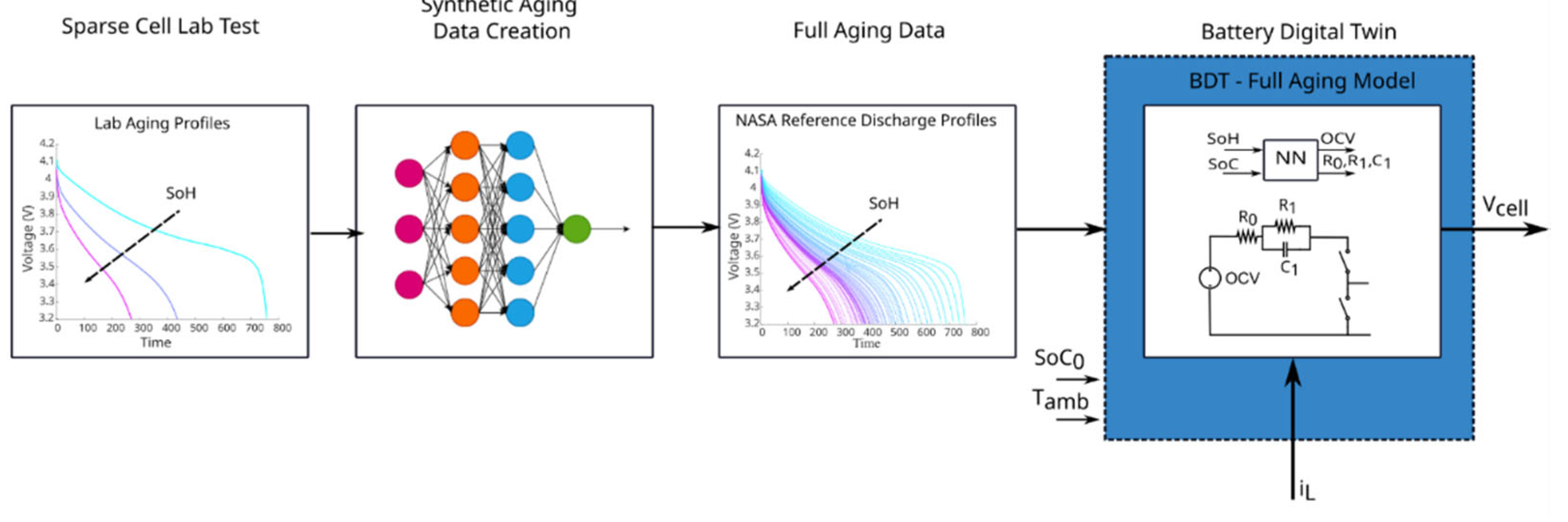
In the case of a Smart Battery concept, the Battery Digital Twin (BDT) is defined as an online digital platform based on an AI core (GPU/TPU) capable of replicating the sensed signals (voltage, state of temperature) of a real cell in all possible operating conditions in terms of loading (current), ambient temperature, and aging. A full cell aging model (CAM) is developed using a sparse laboratory testing dataset (full charging/discharging curves at relevant temperature) that is further expanded by using AI techniques of domain adaptation (part of transfer learning) to cover the whole working/aging domain, as depicted in Figure 9.
The CAM BDT is first developed in Python and then implemented in an AI-core platform (Google Coral Edge), and then it can be used as a development tool for the Smart Battery for:
- Providing a training dataset for SOH estimation/prediction;
- Validation of battery performance optimization (BPO);
- Predictive maintenance.
Training of SOH estimation/prediction using AI using CAM BDT is shown in Figure 10. The CAM BDT can not only synthetically generate a full aging data set, but as also runs in a virtual space in which time can be accelerated, and thus the required lab testing time for the conventional approach can be reduced by several orders of magnitude.
5.2. Validation of Battery Performance Optimization
The Smart Battery allows performance optimization due to the unique feature of cell-level load management enabled by the bypass device. The action of bypassing a cell in the pack during charging or discharging mode can improve balancing in SOC, SOH, and SOT and maximize the SOH, both actions leading to lifetime maximization. As the processes are very complex, AI techniques are used for both training and operational optimization. The BDT is used to validate the performance optimization in an HIL environment including a battery cell simulator (BCS), as illustrated in Figure 11.
5.3. Predictive Diagnostic
The BDT is implemented online in each cell processor as shown in Figure 12. The idea is that the BDT is fed with the real current measurement and temperature estimation, and calculates the output voltage, which is compared with the real voltage measurement. Any large deviation will be interpreted as a potential condition for failure and will be processed accordingly. With this approach, dangerous events such as thermal runaway events can be avoided.
6. Performance Optimization of the Smart Battery
The electrochemical performance of a battery is defined in terms of three parameters, namely the battery capacity, which measures the total charge stored in a battery, the open circuit voltage or the maximum terminal voltage with no current flow, and the internal resistance, which represents the degree to which the component materials impede the flow of ions during battery operation [45]. Battery performance degrades as the battery ages due to repetitive cycling of lithium ions, which leads to degradation modes such as loss of lithium ions and loss of lithium inventory to set in. This battery aging phenomenon leads to increased internal resistance along with capacity and power fade during a battery’s lifetime. To optimize this threefold battery performance, it is crucial to understand the degradation phenomenon and correlate it with measurable battery states. Based on the pre-trained AI-based battery aging models as discussed in previous sections, from measured data, namely terminal current, voltage, and surface temperature, the battery internal states can be evaluated, namely SOH, SOP, SOE, and SOT.
Using these states of the battery, which we define as health indicators, a numerical optimization can be developed that considers operational and power constraints of the battery with the potential to maximize SOH for example. Here, we use reward-based learning to adaptively learn from the battery environment or the balance of the system such as the EV power train and desired user performance to ensure the states of the battery are maximized. It must be noted that since the discharging profile is not in our control, we focus on the charging profile and use the bypass action of Smart Battery slave boards to charge or bypass a battery cell at any given point in time. A complete representation of the aforementioned methodology of battery performance optimization is presented in Figure 13. The goal of this complete optimization as shown in Figure 11 is to extend the lifetime of the batteries, keep the operational cost minimal and maximize the system reliability by embedding fault diagnosis within the system architecture.
A more detailed overview of how this battery performance optimization works is shown below with a simplified flow diagram in Figure 14, wherein the performance optimization, preventive diagnostics, and BDT containing the CAM act together in the local cloud to achieve the user-desired and constrained available performance metric, which is an output of the optimization algorithm. The comparison of these two parameters determines whether the bypass switches should connect or disconnect a battery cell while charging. This is in line with the previously discussed results of pulse charging leading to an extended lifetime of the battery, and bypass switches make it possible.
7. Applications of the Smart Battery
A natural question that arises regards the contribution of Smart Batteries to the field of power and energy systems, which spans many directions as shown in Figure 15. Starting from energy storage in power grids to maximum power point tracking in solar photovoltaics, the Smart Battery widely covers the generation, transmission, and distribution sectors of electrical energy. Vehicle-to-grid is an upcoming industry and is anticipated to be limited by battery cycling and aging constraints, but with the Smart Battery, this can be effectively overcome. With green transition as the target of many developing and developed nations, transportation electrification for rail, road, and airways is being investigated. This requires electric vehicles to have reliable, high-performing, and long-lasting batteries, requirements that are the core fundamentals on which the Smart Battery is designed. One major challenge in the EV industry is the rising fast charging industry, which is known to degrade batteries and accelerate their aging. With lifetime extension as a key objective in battery performance optimization, this challenge can be positively overcome using the Smart Battery. We also argue that with Smart Battery technologies, Li-ion batteries can be easily reconfigured for residential energy storage due to lower power and capacity fade in Smart Batteries. Overall, the Smart Battery technology can revolutionize the green energy transition by making disruptive ideas such as ultra-fast charging, second lifetime, and V2G a reality.
Author Contributions
Conceptualization, R.T.; methodology, R.T., X.S., S.B.V. and D.-I.S.; software, X.S., S.B.V. and D.-I.S.; validation, X.S., S.B.V. and A.K.; formal analysis, R.T., X.S., A.K., P.B. and D.-I.S.; investigation, R.T., X.S., S.B.V., A.K., P.B. and D.-I.S.; writing—original draft preparation, R.T, X.S., S.B.V., P.B., A.K. and D.-I.S.; writing—review and editing, X.S., D.-I.S. and R.T.; supervision, R.T.; funding acquisition, R.T. All authors have read and agreed to the published version of the manuscript.
Funding
This research was funded by the “SMART BATTERY” project, granted by Villum Foundation in 2021 (project number 222860).
Conflicts of Interest
The authors declare no conflict of interest.
References
- Teodorescu, R.; Sui, X.; Acharya, A.B.; Stroe, D.I.; Huang, X. Smart battery concept: A battery that can breathe. In Proceedings of the 5th E-Mobility Power System Integration Symposium (EMOB 2021), Hybrid Conference, Berlin, Germany, 27 September 2021; pp. 214–220. [Google Scholar]
- Datasheet, Automotive grade MOSFET AUIRF8739L2TR, International Rectifier. Available online: https://www.infineon.com/cms/en/product/power/mosfet/automotive-mosfet/auirf8739l2/ (accessed on 10 August 2022).
- Application Note, SimpleLink Microcontroller Platform, Texas Instruments. Available online: https://www.ti.com/lit/pdf/swat002 (accessed on 10 August 2022).
- Datasheet, CC2642R SimpleLink™ Bluetooth® 5.2 Low Energy Wireless MCU, Texas Instruments. Available online: https://www.ti.com/document-viewer/cc2642r/datasheet (accessed on 10 August 2022).
- Archambeault, B.R.; Drewniak, J. PCB Design for Real-World EMI Control; Springer Science & Business Media: Berlin, Germany, 2013; Volume 696. [Google Scholar]
- Feng, X.; Ouyang, M.; Liu, X.; Lu, L.; Xia, Y.; He, X. Thermal runaway mechanism of lithium ion battery for electric vehicles: A review. Energy Storage Mater. 2018, 10, 246–267. [Google Scholar] [CrossRef]
- Liu, Y.; Zhu, Y.; Cui, Y. Challenges and opportunities towards fast-charging battery materials. Nat. Energy 2019, 4, 540–550. [Google Scholar] [CrossRef]
- Tomaszewska, A.; Chu, Z.; Feng, X.; O’Kane, S.; Liu, X.; Chen, J.; Ji, C.; Endler, E.; Li, R.; Liu, L.; et al. Lithium-ion battery fast charging: A review. ETransportation 2019, 1, 100011. [Google Scholar] [CrossRef]
- Hu, X.; Zheng, Y.; Howey, D.A.; Perez, H.; Foley, A.; Pecht, M. Battery warm-up methodologies at subzero temperatures for automotive applications: Recent advances and perspectives. Prog. Energy Combust Sci. 2020, 77, 100806. [Google Scholar] [CrossRef]
- Rodrigues, M.T.F.; Babu, G.; Gullapalli, H.; Kalaga, K.; Sayed, F.N.; Kato, K.; Joyner, J.; Ajayan, P.M. A materials perspective on Li-ion batteries at extreme temperatures. Nat. Energy 2017, 2, 17108. [Google Scholar] [CrossRef]
- Lin, X.; Khosravinia, K.; Hu, X.; Li, J.; Lu, W. Lithium plating mechanism, detection, and mitigation in lithium-ion batteries. Prog. Energy Combust. Sci. 2021, 87, 100953. [Google Scholar] [CrossRef]
- Edge, J.S.; O’Kane, S.; Prosser, R.; Kirkaldy, N.D.; Patel, A.N.; Hales, A.; Ghosh, A.; Ai, W.; Chen, J.; Yang, J.; et al. Lithium ion battery degradation: What you need to know. Phys. Chem. Chem. Phys. 2021, 23, 8200–8221. [Google Scholar] [CrossRef] [PubMed]
- Zhu, G.; Wen, K.; Lv, W.; Zhou, X.; Liang, Y.; Yang, F.; Chen, Z.; Zou, M.; Li, J.; Zhang, Y.; et al. Materials insights into low-temperature performances of lithium-ion batteries. J. Power Sources 2015, 300, 29–40. [Google Scholar] [CrossRef]
- Yang, X.G.; Liu, T.; Gao, Y.; Ge, S.; Leng, Y.; Wang, D.; Wang, C.Y. Asymmetric Temperature Modulation for Extreme Fast Charging of Lithium-Ion Batteries. Joule 2019, 3, 3002–3019. [Google Scholar] [CrossRef]
- Zhu, J.G.; Sun, Z.C.; Wei, X.Z.; Dai, H.F. A new lithium-ion battery internal temperature on-line estimate method based on electrochemical impedance spectroscopy measurement. J. Power Sources 2015, 274, 990–1004. [Google Scholar] [CrossRef]
- Kim, Y.; Mohan, S.; Siegel, J.B.; Stefanopoulou, A.G.; Ding, Y. The estimation of temperature distribution in cylindrical battery cells under unknown cooling conditions. IEEE Trans. Control Syst. Technol. 2014, 22, 2277–2286. [Google Scholar]
- Ojo, O.; Lang, H.; Kim, Y.; Hu, X.; Mu, B.; Lin, X. A neural network based method for thermal fault detection in lithium-ion batteries. IEEE Trans. Ind. Electron. 2021, 68, 4068–4078. [Google Scholar] [CrossRef]
- Li, M.; Dong, C.; Mu, Y.; Yu, X.; Xiao, Q.; Jia, H. Data-model alliance network for the online multi-step thermal warning of energy storage system based on surface temperature diffusion. Patterns 2022, 3, 100432. [Google Scholar] [CrossRef]
- Surya, S.; Samanta, A.; Marcis, V.; Williamson, S. Hybrid electrical circuit model and deep learning-based core temperature estimation of lithium-ion battery cell. IEEE Trans. Transp. Electrif. 2022, 8, 3816–3824. [Google Scholar] [CrossRef]
- Aykol, M.; Gopal, C.B.; Anapolsky, A.; Herring, P.K.; van Vlijmen, B.; Berliner, M.D.; Bazant, M.Z.; Braatz, R.D.; Chueh, W.C.; Storey, B.D. Perspective—Combining physics and machine learning to predict battery lifetime. J. Electrochem. Soc. 2021, 168, 030525. [Google Scholar] [CrossRef]
- Richardson, R.R.; Ireland, P.T.; Howey, D.A. Battery internal temperature estimation by combined impedance and surface temperature measurement. J. Power Sources 2014, 265, 254–261. [Google Scholar] [CrossRef]
- Richardson, R.R.; Howey, D.A. Sensorless battery internal temperature estimation using a Kalman filter with impedance measurement. IEEE Trans. Sustain. Energy 2015, 6, 1190–1199. [Google Scholar] [CrossRef] [Green Version]
- Broussely, M.; Biensan, P.; Bonhomme, F.; Blanchard, P.; Herreyre, S.; Nechev, K.; Staniewicz, R.J. Main aging mechanisms in Li ion batteries. J. Power Sources 2005, 146, 90–96. [Google Scholar] [CrossRef]
- Escobar, L.A.; Meeker, W.Q. A review of accelerated test models. Stat. Sci. 2006, 21, 552–577. [Google Scholar] [CrossRef] [Green Version]
- Ren, L.; Zhao, L.; Hong, S.; Zhao, S.; Wang, H.; Zhang, L. Remaining useful life prediction for lithium-ion battery: A deep learning approach. IEEE Access 2018, 6, 50587–50598. [Google Scholar] [CrossRef]
- Farmann, A.; Waag, W.; Marongiu, A.; Sauer, D.U. Critical review of on-board capacity estimation techniques for lithium-ion batteries in electric and hybrid electric vehicles. J. Power Sources 2015, 281, 114–130. [Google Scholar] [CrossRef]
- Ng, M.F.; Zhao, J.; Yan, Q.; Conduit, G.J.; Seh, Z.W. Predicting the state of charge and health of batteries using data-driven machine learning. Nat. Mach. Intell. 2020, 2, 161–170. [Google Scholar] [CrossRef] [Green Version]
- Sui, X.; He, S.; Vilsen, S.B.; Meng, J.; Teodorescu, R.; Stroe, D.I. A review of non- probabilistic machine learning-based state of health estimation techniques for lithium-ionbattery. Appl. Energy 2021, 300, 117346. [Google Scholar] [CrossRef]
- Zou, C.; Manzie, C.; Nešić, D.; Kallapur, A.G. Multi-time-scale observer design for state-of-charge and state-of-health of a lithium-ion battery. J. Power Sources 2016, 335, 121–130. [Google Scholar] [CrossRef]
- Murphy, K.P. Machine Learning: A Probabilistic Perspective; MIT Press: Cambridge, MA, USA, 2012. [Google Scholar]
- Sui, X.; He, S.; Meng, J.; Teodorescu, R.; Stroe, D.I. Fuzzy entropy-based state of health estimation for Li-ion batteries. IEEE Trans. Emerg. Sel. Topics Power Electron 2021, 9, 5125–5137. [Google Scholar] [CrossRef]
- Sui, X.; Stroe, D.I.; He, S.; Huang, X.; Meng, J.; Teodorescu, R. The effect of voltage dataset selection on the accuracy of entropy-based capacity estimation methods for lithium-ion batteries. Appl. Sci. 2019, 9, 4170. [Google Scholar]
- Sui, X.; He, S.; Huang, X.; Teodorescu, R.; Stroe, D.I. Data smoothing in fuzzy entropy-based battery state of health estimation. In Proceedings of the IECON 2020 The 46th Annual Conference of the IEEE Industrial Electronics Society, Singapore, 18–21 October 2020; pp. 1779–1784. [Google Scholar]
- Che, Y.; Zheng, Y.; Wu, Y.; Sui, X.; Bharadwaj, P.; Stroe, D.I.; Yang, Y.; Hu, X.; Teodorescu, R. Data efficient health prognostic for batteries based on sequential information-driven probabilistic neural network. Appl. Energy 2022, 323, 119663. [Google Scholar] [CrossRef]
- Pan, S.J.; Yang, Q. A survey on transfer learning. IEEE Trans. Knowl. Data Eng. 2009, 22, 1345–1359. [Google Scholar] [CrossRef]
- Sui, X.; He, S.; Teodorescu, R.; Stroe, D.I. Fast and robust estimation of Lithium-ion batteries state of health using ensemble learning. In Proceedings of the 2021 IEEE Energy Conversion Congress and Exposition (ECCE), Vancouver, BC, Canada, 10–14 October 2021; pp. 1393–1399. [Google Scholar]
- Lin, C.; Tang, A.; Wang, W. A review of SOH estimation methods in Lithium-ion batteries for electric vehicle applications. Energy Procedia 2015, 75, 1920–1925. [Google Scholar] [CrossRef] [Green Version]
- Wu, Y.; Xue, Q.; Shen, J.; Lei, Z.; Chen, Z.; Liu, Y. State of health estimation for lithium-ion batteries based on healthy features and long short-term memory. IEEE Access 2020, 8, 28533–28547. [Google Scholar] [CrossRef]
- You, G.W.; Park, S.; Oh, D. Real-time state-of-health estimation for electric vehicle batteries: A data-driven approach. Appl. Energy 2016, 176, 92–103. [Google Scholar] [CrossRef]
- Ma, G.; Zhang, Y.; Cheng, C.; Zhou, B.; Hu, P.; Yuan, Y. Remaining useful life prediction of lithium-ion batteries based on false nearest neighbors and a hybrid neural network. Appl. Energy 2019, 253, 113626. [Google Scholar] [CrossRef]
- Chaoui, H.; Ibe-Ekeocha, C.C. State of charge and state of health estimation for lithium batteries using recurrent neural networks. IEEE Trans. Veh. Technol. 2017, 66, 8773–8783. [Google Scholar] [CrossRef]
- Rubin, D.B. Bayesianly justifiable and relevant frequency calculations for the applied statistician. Ann. Stat. 1984, 12, 1151–1172. [Google Scholar] [CrossRef]
- Diggle, P.J.; Gratton, R.J. Monte Carlo methods of inference for implicit statistical models. J. R. Stat. Soc. Ser. B (Methodol.) 1984, 46, 193–212. [Google Scholar] [CrossRef]
- Price, L.F.; Drovandi, C.C.; Lee, A.; Nott, D.J. Bayesian synthetic likelihood. J. Comput. Graph. Stat. 2018, 27, 1–11. [Google Scholar] [CrossRef]
- Harmon, J.E. Assessing Battery Performance: Compared to What? Argon National Lab.: Lemont, IL, USA, 2019. Available online: https://www.anl.gov/article/assessing-battery-performance-compared-to-what (accessed on 10 August 2022).
Figure 1.
Lifetime extension using pulsed current charging compared with constant current [1].
Figure 1.
Lifetime extension using pulsed current charging compared with constant current [1].

Figure 2.
High-level architecture showing Smart Battery with slave controllers and a master controller.
Figure 2.
High-level architecture showing Smart Battery with slave controllers and a master controller.

Figure 3.
The operation mode of the switching device: (a) inserted; (b) bypassed.

Figure 4.
Hardware components in a Smart Battery cell.

Figure 5.
Smart Battery hardware design concept for high Ah prismatic cells.

Figure 6.
Smart Battery functionalities enabled by SOT estimation.

Figure 7.
Framework of temperature distribution estimation using PINN: Measured temperature data at the battery surface and core are used for training the data-driven model (e.g., based on deep neural networks); then a physics part is added as a regularization term to further train the deep neural network so that the estimated temperature not only follows the patterns of data in the training set but also obeys the spatiotemporal physical law in the physics part. The network is trained by minimizing both the loss of the measured data and the loss of the physics part after 10,000 epochs or more, where an appropriate λ should be selected to adjust the relative importance between data loss and physics loss. The training process can adjust the weights and bias in neural networks, as well as identify unknown parameters in PDE simultaneously (where T represents the temperature, t represents the time, I represents the current, V represents the voltage, r represents the space distribution, Q represents the heat generation, cp represents the specific heat capacity, Vb represents the volume of the battery, MSE represents the mean squared error, MSEdata represents the mean squared error of the temperature estimation based on the measured data, MSEphysics represents the mean squared error of the temperature estimation in physics part, kt represents the thermal conductivity of the cell, and λ represents coefficient between data loss and physics loss).

Figure 8.
A flowchart of the Smart Battery SOH and RUL prediction framework. In order to stabilize the predictions of the SOH, the time dependence of the system is moved from the SOH to the features. To predict the SOH, the features are predicted forward in time, and a SOH estimation model is then used to predict the SOH.

Figure 9.
Concept of CAM BDT.

Figure 10.
Training of SOH estimation using CAM BDT. SOH* represents the reference value.

Figure 11.
SOH maximization as an example of BPO using BDT. SOHmax represents the maximum value of the optimization objective SOH, and V* is the voltage reference.
Figure 11.
SOH maximization as an example of BPO using BDT. SOHmax represents the maximum value of the optimization objective SOH, and V* is the voltage reference.

Figure 12.
BDT used in predictive diagnostics.

Figure 13.
A flowchart of the BPO framework, showing the use of reward-based learning for optimizing the charging profile of Li-ion batteries by using measured V, I, and T. The brain of the system is physics-informed and maps degradation modesto quantifiable health indicators to achieve an extended lifetime of batteries along with added features of fault diagnosis and cost minimization. A user interface makes the entire approach more pragmatic for an EV scenario with varying load profiles and desired performance as per the user’s needs and constraints.

Figure 14.
A detailed overview of the Smart Battery system with various attributes including optimization of SOX (SOP, SOE, SOT, and SOH). Based on whether the performance is optimized or not, the bypass switches act to activate or provide rest to a cell. The cell aging model is built on AI trained neural network blocks that fully emulate a real battery aging mechanism for given user load profiles and desired performance with a given aging condition of the battery as the initial state of operation.

Figure 15.
The performance-optimized Smart Batteries find applications in energy storage for modern power grids and green microgrids. They can also be readily applied in maximum power point tracking in photovoltaic applications by acting as a controlled voltage source. With the fast-growing EV industry, the role of a high-performing Smart Battery is inevitable for fast charging and lifetime extension, which is also applicable to the electric aircraft industry. The second lifetime of batteries is the sustainable way of reusing EV batteries in residential energy storage with reduced capacity fade using the Smart Battery system.


Table 1.
Commercially available MOSFETs with very low on-resistance for minimizing the power loss in a Smart Battery.
Table 1.
Commercially available MOSFETs with very low on-resistance for minimizing the power loss in a Smart Battery.
| MOSFET | Rds,on (mΩ) | Rated Current (A) | Power Loss at 50 A (W) |
|---|---|---|---|
| IPT004N03L | 0.4 | 300 | 1 |
| IST006N04NM6 | 0.6 | 475 | 1.5 |
| IRL40SC209 | 0.8 | 478 | 2 |
| AUIRF8739L2TR | 0.35 | 545 | 0.875 |
Publisher’s Note: MDPI stays neutral with regard to jurisdictional claims in published maps and institutional affiliations. |
© 2022 by the authors. Licensee MDPI, Basel, Switzerland. This article is an open access article distributed under the terms and conditions of the Creative Commons Attribution (CC BY) license (https://creativecommons.org/licenses/by/4.0/).
Share and Cite
MDPI and ACS Style
Teodorescu, R.; Sui, X.; Vilsen, S.B.; Bharadwaj, P.; Kulkarni, A.; Stroe, D.-I. Smart Battery Technology for Lifetime Improvement. Batteries 2022, 8, 169. https://doi.org/10.3390/batteries8100169
AMA Style
Teodorescu R, Sui X, Vilsen SB, Bharadwaj P, Kulkarni A, Stroe D-I. Smart Battery Technology for Lifetime Improvement. Batteries. 2022; 8(10):169. https://doi.org/10.3390/batteries8100169
Chicago/Turabian StyleTeodorescu, Remus, Xin Sui, Søren B. Vilsen, Pallavi Bharadwaj, Abhijit Kulkarni, and Daniel-Ioan Stroe. 2022. "Smart Battery Technology for Lifetime Improvement" Batteries 8, no. 10: 169. https://doi.org/10.3390/batteries8100169
Note that from the first issue of 2016, this journal uses article numbers instead of page numbers. See further details here.