1. Introduction
Storage systems are gaining more interest as alternative energy because of rising environmental concerns and the limited accessibility of fossil fuels. The significance of storage devices and energy conversion has enhanced owing to the requirement for mobile and stationary energy. Lithium-ion batteries have been achieving acceptance as the preliminary technology for energy storage applications. They have several advantages such as high specific energy densities, high energy density, and long cycling life.
Battery models are a vital component of a dynamic electric vehicle simulator [
1]. Battery modelling plays an important role in the approximation of battery performance and in design. Batteries have nonlinear behavior, and creating trustworthy, reliable, and realistic models in order to be able to control them is essential. Batteries go under certain cycles at the same time, taking into consideration there are some environmental conditions affecting the performance of the system, so it is indispensable to improve battery models which accurately simulate real battery characteristics.
Battery models are important for several reasons. Batteries are an essential part of a complicated system that provides critical information to controllers, so it is necessary for control engineers to develop algorithms for battery management systems. System engineers need to integrate batteries into bigger systems and assess their performance via simulations. Battery pack designers are tasked with improving the physical arrangement of the battery pack in order to maximize its performance.
Thévenin-based electrical models and impedance-based electrical models are two main categories of electrical models. Discharging and charging current pulses are used to parameterize the Thévenin-based electrical models [
2]. Electrochemical impedance spectroscopy methods are used to parameterize the impedance-based electrical models [
3].
It is possible to count on a trustworthy model to replace the battery with something that behaves like a battery, such as an equivalent circuit model. An equivalent circuit model is the most straight-forward and conventional method for characterizing the dynamic behavior of a lithium-ion battery [
4]. A second-order equivalent circuit was suggested by Thanagasundram et al., and the parameters identification procedure was represented by using a hybrid power pulse characterization test [
4]. The parameter identification and modelling procedure was accomplished in Matlab. In addition, an investigation was accomplished to study how battery cell chemistry affects the suggested model. The comparison among simulation and measurement demonstrated a good accordance [
4].
Parameter identification for a Simulink model of a lithium-ion battery in a hybrid power system was investigated in [
5]. Two experiments were completed for the battery. In addition, a procedure for determining battery cell model parameters by using the experiments was developed. Simulation outcomes were compared to the experimental data, and a high degree of agreement was seen [
5].
A comprehensive, intuitive, and precise electrical battery model was suggested in Reference [
6]. All of the dynamic characteristics of the battery (e.g., temperature, current, nonlinear open-circuit voltage, and cycle number) were considered in the model. A simplified model ignoring the effects of temperature, cycle number, and self-discharge was validated with experimental data. It was concluded that the model could also be simply developed to other energy sourcing and battery technologies [
6].
An automated test system was designed by Schweighofer et al. [
7]. A battery cell model was parameterized based on the obtained data, and the collected results were discussed [
7]. A procedure for determination of the state of charge of lithium-ion batteries based on an extended Kalman filter and two distinct equivalent circuit diagrams was described in Reference [
8]. In addition, parameter identification of the circuits was described by using characteristic measurements. It was seen that computation results and measurement were in good agreement [
8].
An analytical parameter identification procedure was presented for lithium-ion batteries based on the Thévenin equivalent circuit model. The method was based on the pulse charge and pulse discharge experiments. The application of the procedure was presented for a second-order model and was validated in Reference [
9].
An equivalent electrical circuit model of a Li-ion polymer battery was simulated in a Matlab environment [
10]. Parameters were taken from AC (alternating current) impedance measurements. The model considered the non-homogeneous properties, such as pore geometry and particle size. The experimental and simulated outcomes were compared, and showed that the impedance model could precisely anticipate the dynamic and transient behavior and discharge power performance of the Li-ion polymer batteries [
10].
A procedure integrating discharge and charge curves analysis and electrochemical impedance spectroscopy for Li-ion batteries was developed by Dong et al. The experimental and simulated outcomes were compared. It was concluded that the developed procedure presented precise estimation of the dynamic behavior of Li-ion batteries over a wide range of discharge and charge currents, and state of charge [
11].
A new method for the electrical circuit modelling of a Li-ion battery was proposed by Saxena et al. The model was fast, simple, and not memory intensive. Furthermore, it did not contain any look-up table. The accuracy of the model was validated with experimental outcomes [
12].
In this investigation the current pulse method was employed with the intention of parameterizing and developing a model of a 13 Ah lithium titanate oxide battery. In addition, an equivalent electrical circuit was employed to approximate the dynamics of the battery cell.
The procedure for battery parameterization, arrangement of the suggested battery dynamic model, and outcomes from the comprehensive battery characterization experiments are described in the following sections.
2. Structure of the Proposed Model
In this investigation, an equivalent electrical circuit model (shown in
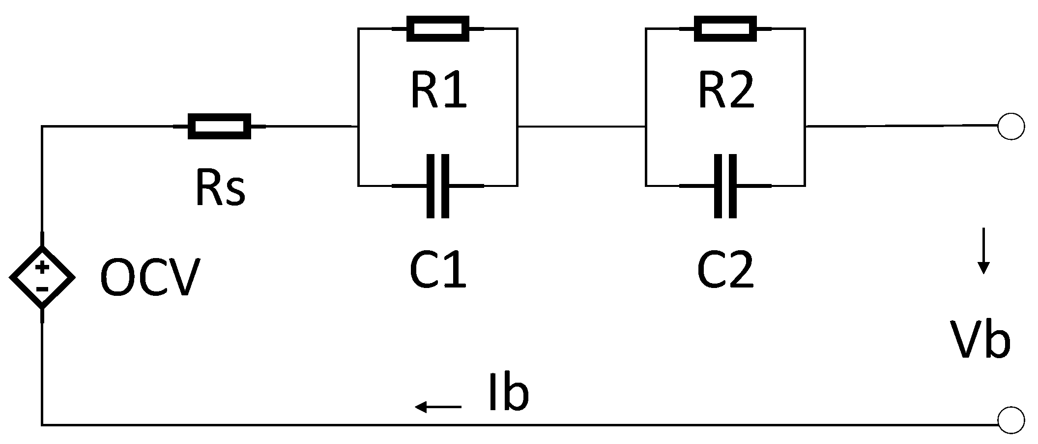
Figure 1) is suggested for simulation purposes and to model the transient behavior of a lithium titanate oxide battery cell. This method was used because this topology generally proposes a tradeoff between battery cell computational requirements and the approximation of voltage precision. The model was comprised of different parts, such as a series DC internal resistance or ohmic resistance, a DC voltage source, and two RC parallel circuit networks.
Series resistance shows internal DC resistance. This resistance is responsible for the immediate voltage decrease when a current is applied to the battery cell. A DC voltage source or controlled voltage source demonstrates the model open circuit voltage (OCV) of a battery cell. Note that this voltage is dependent on the state of charge (SOC).
To determine the transient response of terminal voltage, two RC parallel networks were employed. The prime RC network (R1 and C1) demonstrated the small-time constant of the battery cell feedback, and was employed to model double layer capacitance and the charge transfer procedures. The secondary RC network (R2 and C2), demonstrated the lengthy-time constant of the battery cell feedback, and was employed to model the diffusion procedures. In the investigated model, the parameters were dependent on current, SOC, and temperature. The construction of each subsystem is described in the following parts.
2.1. SOC Calculation
A subsystem was designed for determination of the
SOC. Current and initial
SOC were considered as inputs to the subsystem. Capacity was considered as a function of current. A lookup table was employed to determine the effect of capacity on the current of the battery cell. The following equation was used for calculation of the
SOC:
where
is capacity,
is current, and
is the initial
SOC.
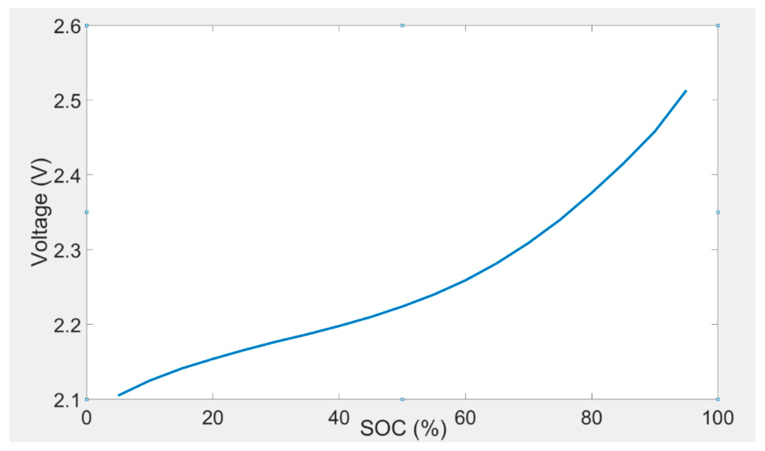
2.2. Open Circuit Voltage Calculation
OCV is the terminal voltage of a battery cell at equilibrium condition. Open circuit voltage is one of the many parameters that need to be determined. The value of
OCV was considered as a function of current rates, temperature, and
SOC. A 2-D lookup table was employed to demonstrate the amount of
OCV. The relationship between
OCV and
SOC could be determined by a polynomial equation. The
OCV of the lithium titanate oxide-based battery was determined over the whole
SOC interval considering a 5%
SOC resolution. The measurements were reproduced for the eight investigated temperatures. The open circuit voltage test method for the battery cell is illustrated in
Table 1. A 2-D lookup table for determination of
OCV is shown in
Table 2. The
OCV and
SOC characteristic, which was determined at 30 °C, is demonstrated in
Figure 2. Analogous outcomes were determined for the other investigated temperatures. It should be noted that 1C corresponds to 13 A.
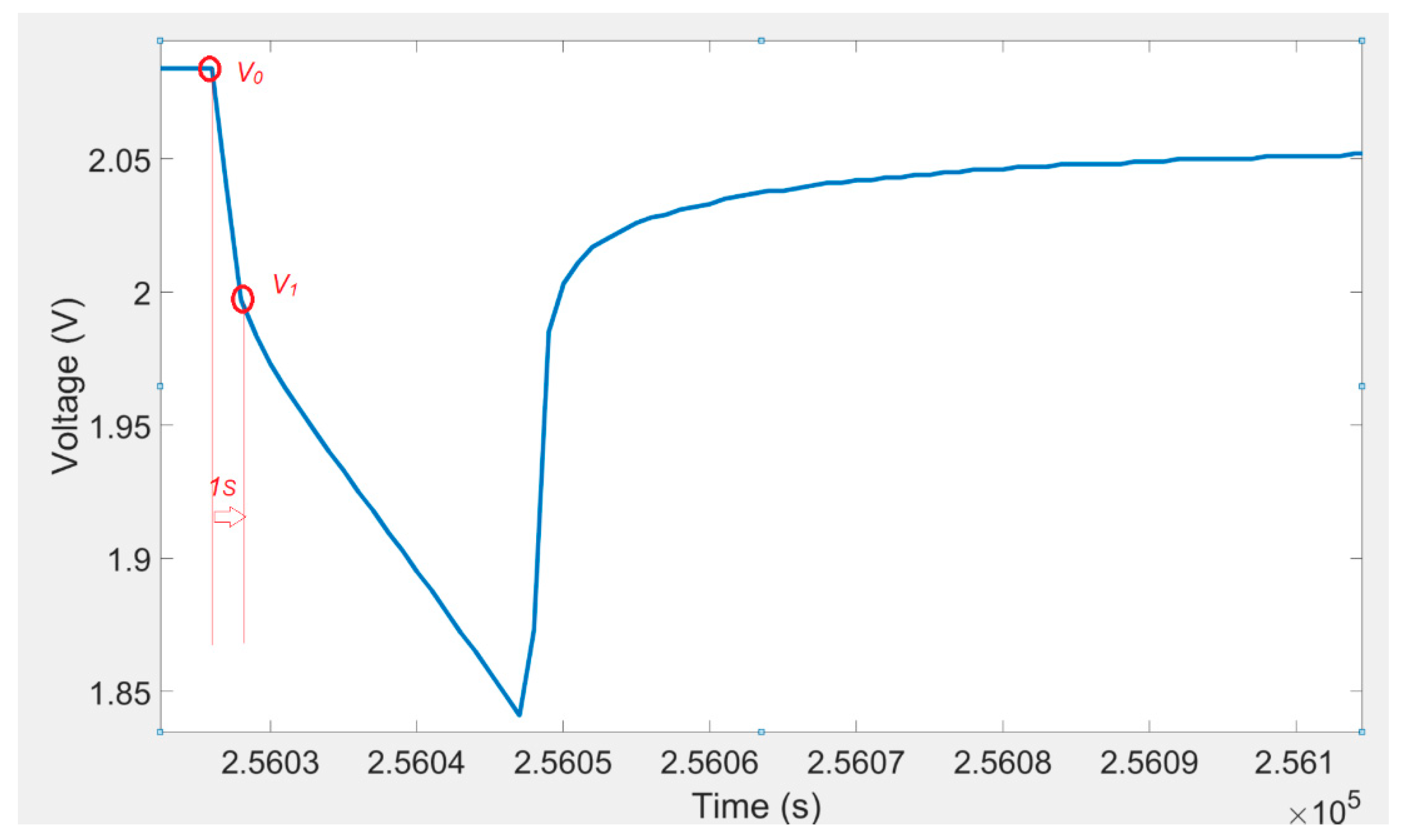
2.3. Calculation of Ohmic Resistance
The ohmic resistance (
) could be determined from the immediate voltage decline after the current pulse was applied. The voltage response of a lithium titanate oxide battery cell to a discharging current pulse (
I) and voltage one second after current pulse is illustrated in
Figure 3. A 2-D lookup table (shown in
Table 3) was used to determine the ohmic resistance. The value of the resistance
was calculated from the following equation:
2.4. RC Values Determination
The amount of RC parallel networks (R1, C1, R2, and C2) were considered as a function of current, SOC, and temperature. In this subsystem, 2-D lookup tables were used to characterize the parameters of RC parallel networks.
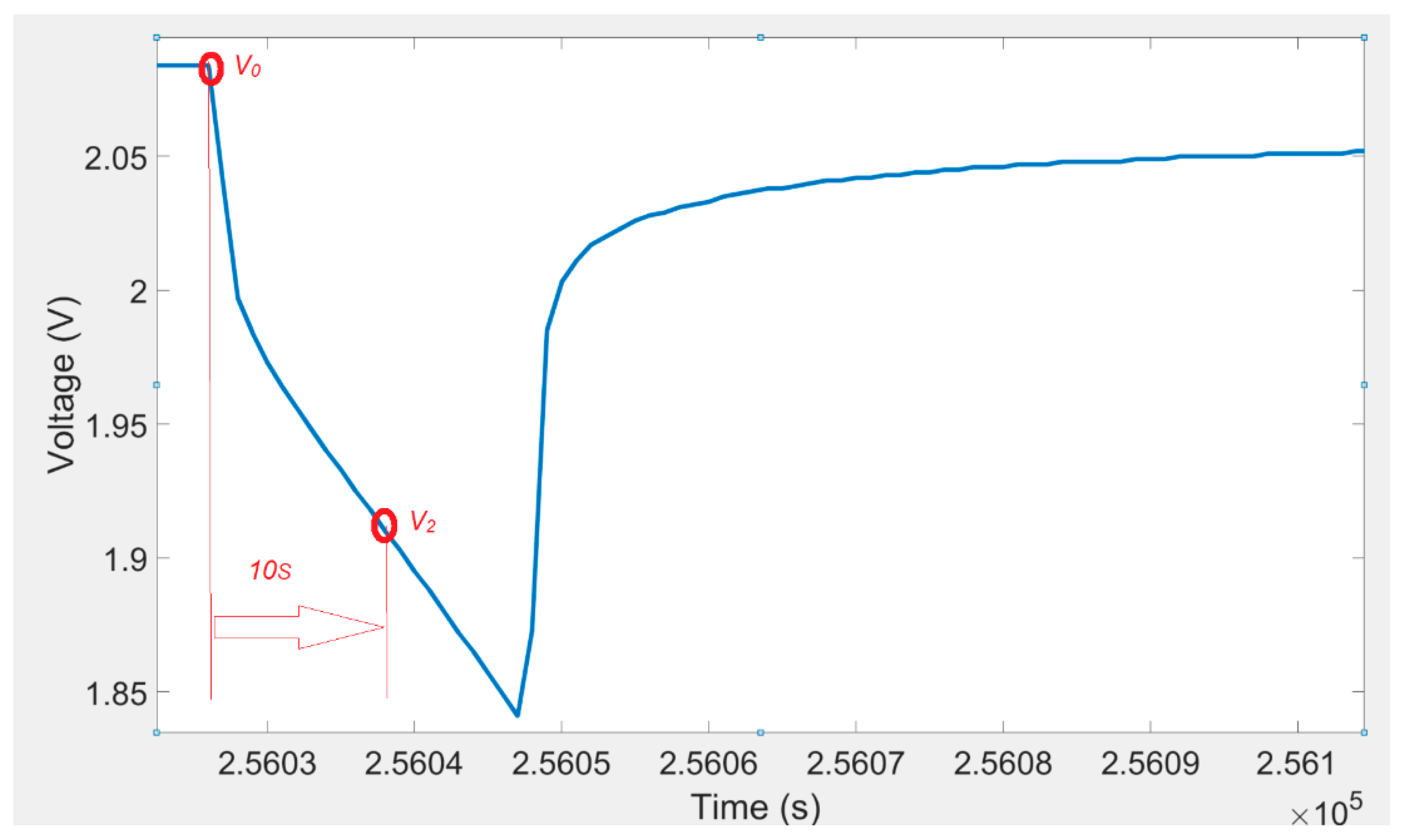
2.5. R1 Calculation
The voltage response of a lithium titanate oxide battery cell to a discharging current pulse and voltage ten seconds after current pulse is illustrated in
Figure 4. The 2-D lookup table shown in
Table 4 was used to determine the
R1. The following equation was used to calculate the value of the resistance
R1:
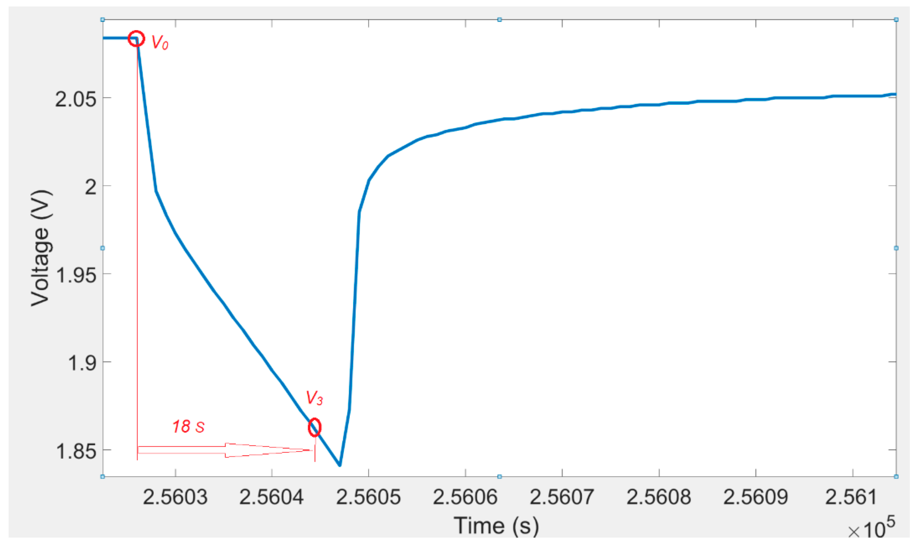
2.6. R2 Calculation
The voltage response of a lithium titanate oxide battery cell to a discharging current pulse and voltage eighteen seconds after a current pulse is illustrated in
Figure 5. A 2-D lookup table (shown in
Table 5) was used to determine the
R2. The values of the resistance
R2 were calculated from the following equation:
2.7. C1 and C2 Calculations
The 2-D lookup tables shown in
Table 6 and
Table 7 were used to determine
C1 and
C2.
The values of the capacitances
C1 and
C2 were determined by using the following equations [
13]:
2.8. Voltages of RC Parallel Networks
The voltages of RC parallel networks (
V1 and
V2) representing transient feedback of the battery cell voltage and were determined by using the following equations:
2.9. Calculation
refers to the voltage reduction from
. The amount of
was considered as a function of
SOC, current, and temperature. Accordingly, a 2-D lookup table was used to demonstrate the amount of
. The amount of
could be easily determined by employing the following equation:
The voltage of the battery cell was calculated by employing the following equation:
3. Experimental Set-Up
The experimental facilities and systems were comprised of a 13 Ah lithium titanate oxide battery which had capacity and nominal voltage of 13.4 Ah and 2.26 V, respectively. Battery experiments were accomplished by employing a Maccor automated test system and a computer to record the outcomes of the battery cell experiments. During all the experiments, the lithium titanate oxide battery cell was located inside a climatic chamber and its voltage, current, and temperatures were regularly controlled and measured by means of a Maccor battery test station.
3.1. Battery Experiments
Pulse charge and discharge experiments were carried out for parameter identification of the battery cell. A thirty-minute rest period was allowed for the battery cell in each cycle to determine voltage transient response and OCV of the battery cell.
Pulse charge and discharge experiments were conducted for 0.25C, 0.5C, 1C, 2C, and 4C. During the battery experiments, the voltage of the battery cell was kept to lower and upper limits equal to 1.5 and 2.8 V respectively, in order to prevent durable damage to the battery cell. These limitations were suggested by the battery cell manufacturer.
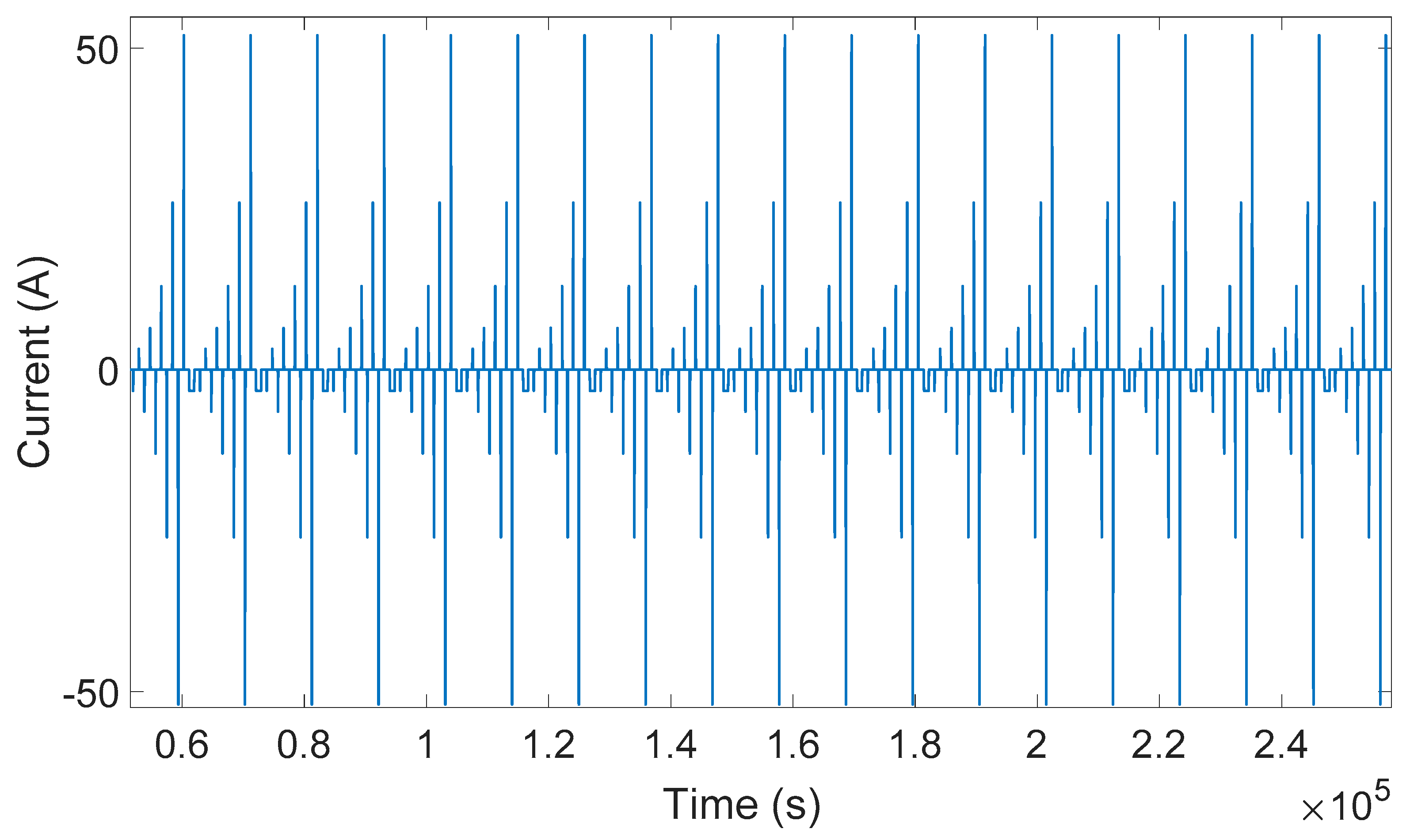
In this investigation, a DC pulse procedure was used for parameterization of the equivalent electrical circuit of the lithium titanate oxide-based battery. The equivalent electrical circuit parameters are variable with temperature, load current, and
SOC. In order to consider all of these dependences, a specific current pulse profile was applied to the battery cell. This load profile was used to extract the equivalent electrical circuit model parameters. At each
SOC level, five charge and discharge current pulses (i.e., 0.25C, 0.5C, 1C, 2C, and 4C) were applied to the battery. This load profile is illustrated in
Figure 6. The
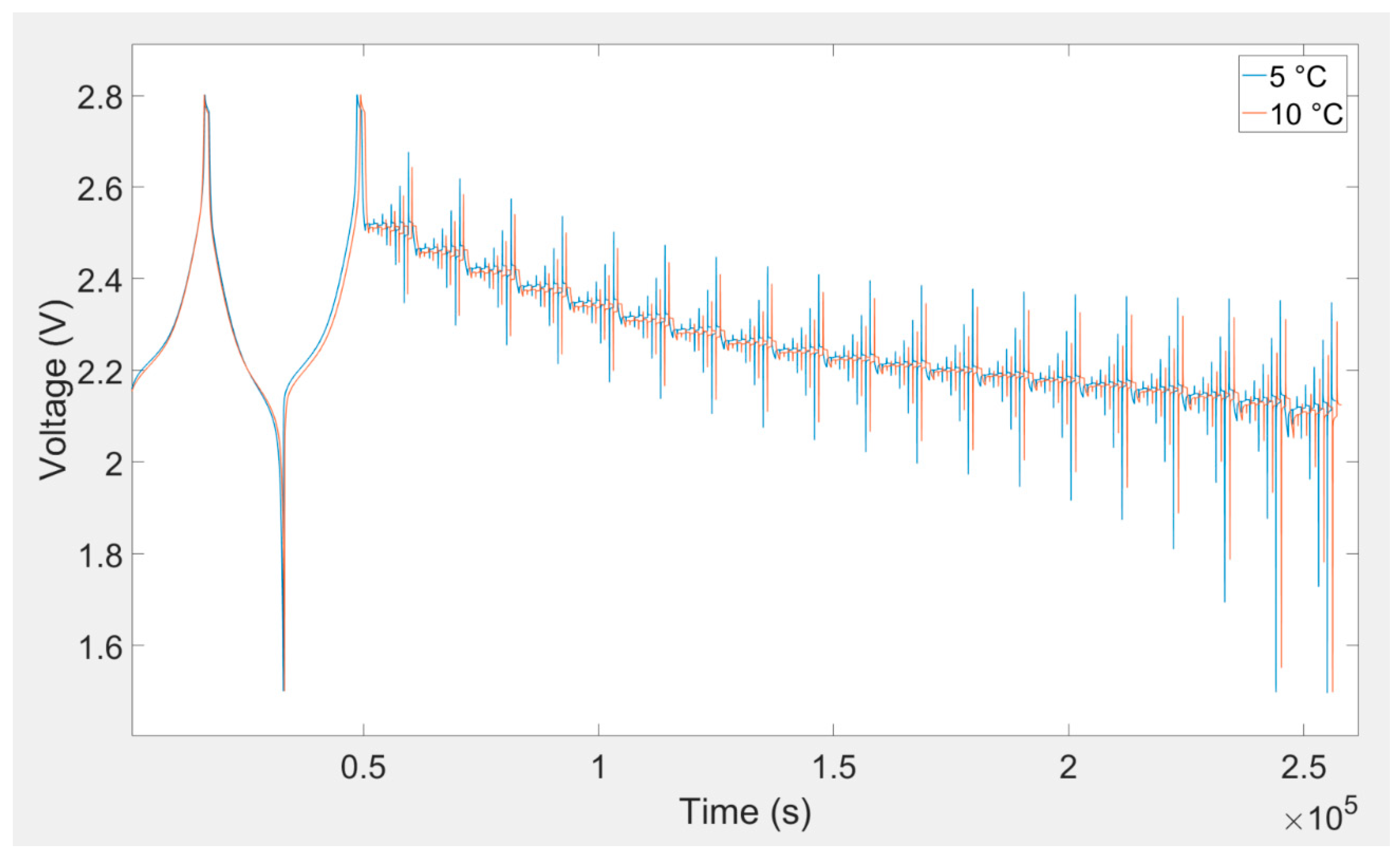
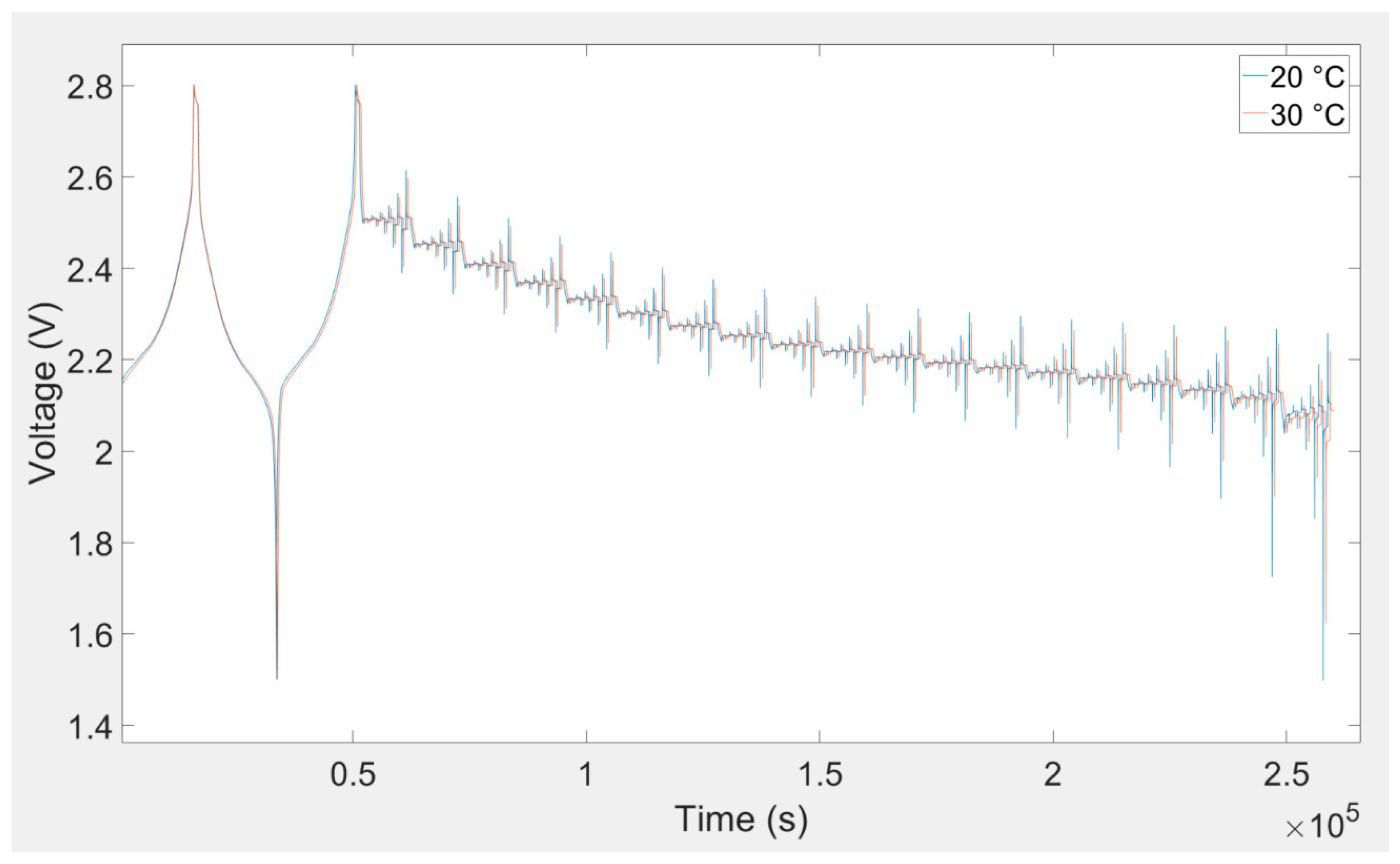
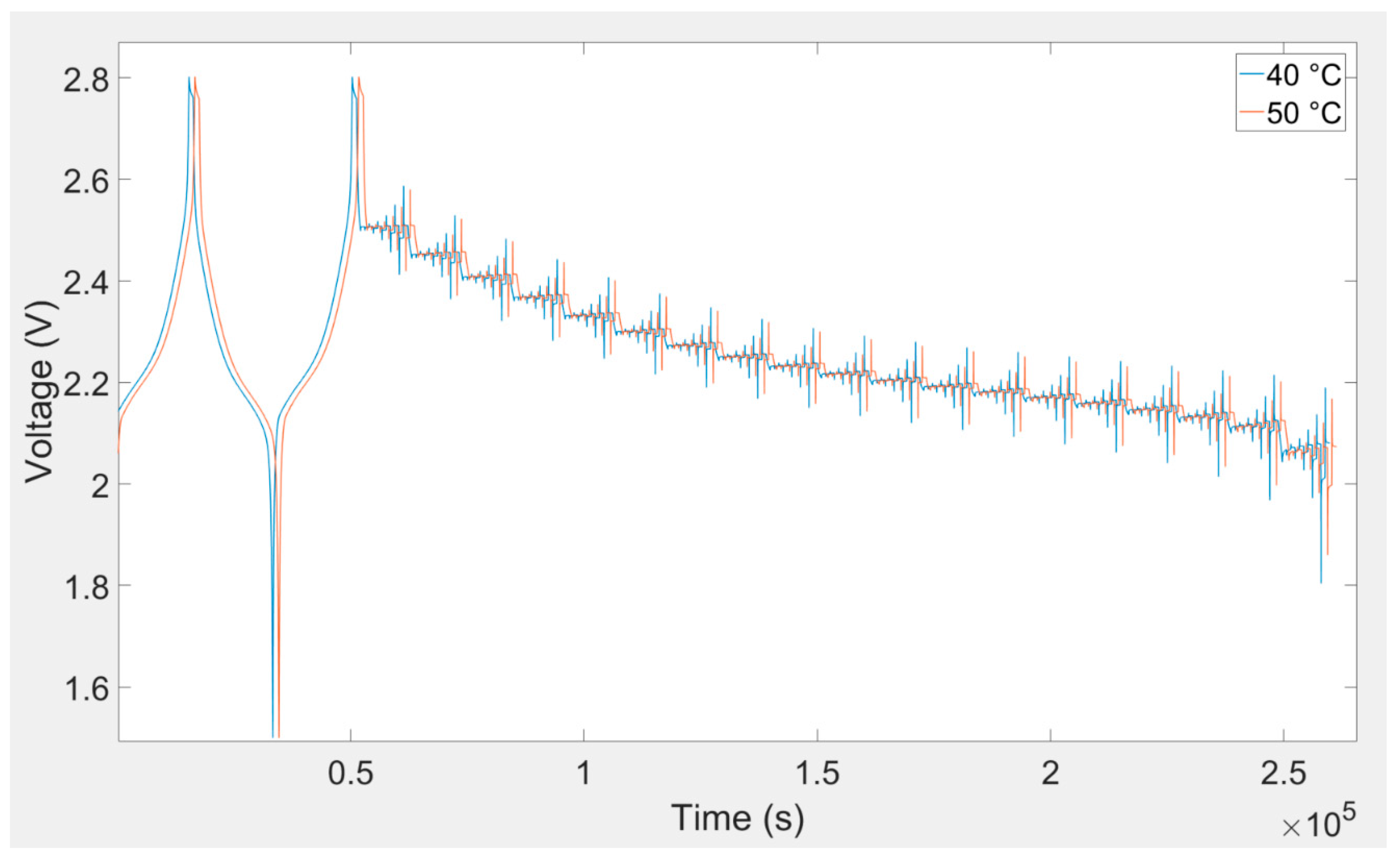
SOC was changed from 5%–95% with 5% resolution. This procedure was repeated for all eight investigated temperatures. Lithium titanate oxide battery cell voltage responses owing to charging and discharging current pulse for different temperatures are illustrated in
Figure 7,
Figure 8 and
Figure 9.
3.2. Model Validation
The equivalent electrical circuit model was able to model the transient response of the battery cell based on different types of current excitation. Different equivalent electrical circuit model procedures were employed to model the dynamic response of lithium-ion batteries.
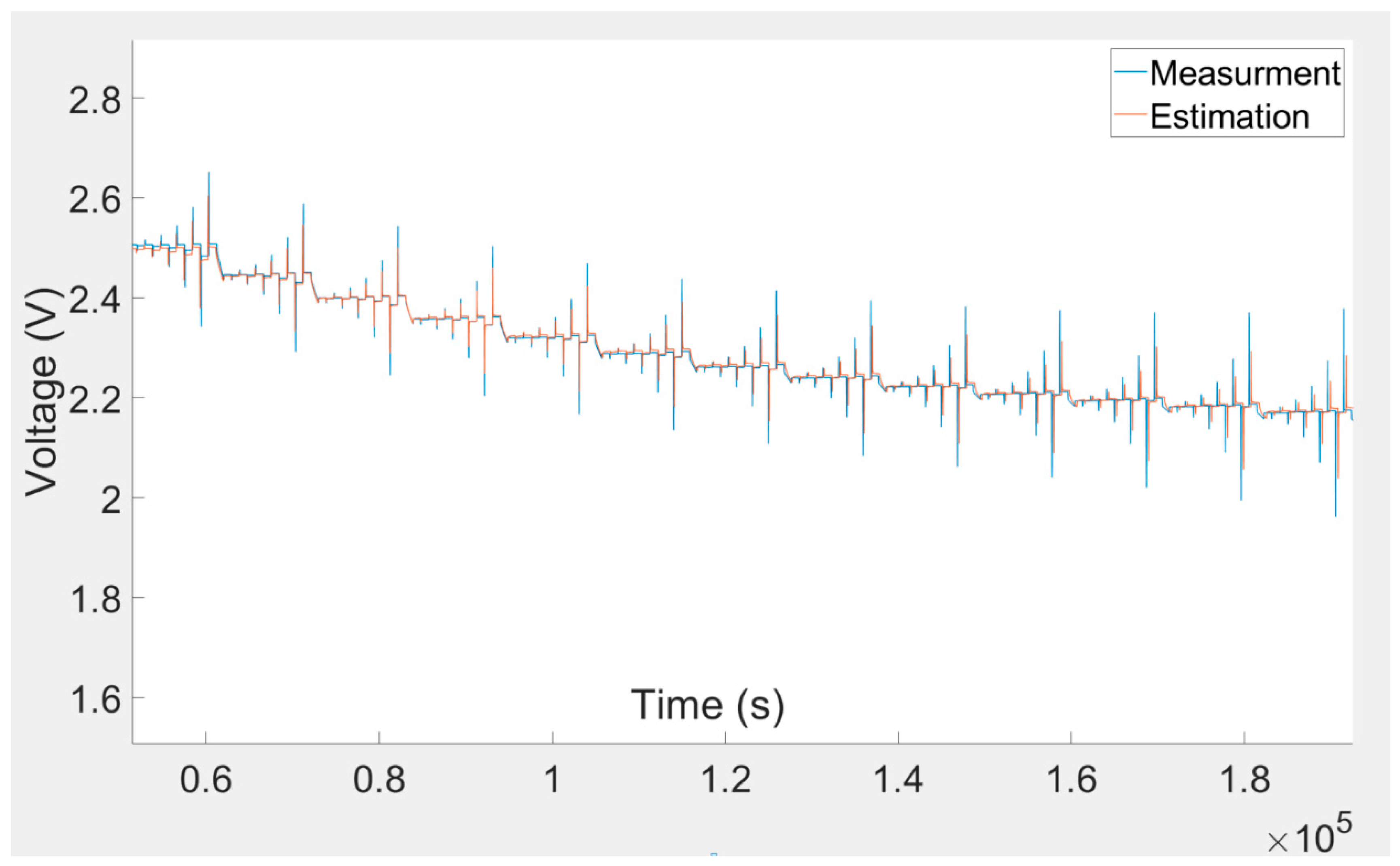
With the intention of validating the suggested model, the simulation results were compared with the corresponding laboratory-measured results. A comparison of the model-estimated and laboratory-measured results for the experiment is shown in
Figure 10. The comparison illustrates that the curves are approximately superimposed. This acknowledges that the model was precise in different charging and discharging situations.


