Article

Degradation Phenomena of Bismuth-Modified Felt Electrodes in VRFB Studied by Electrochemical Impedance Spectroscopy

1
Institute for Chemistry and Biochemistry, Freie Universität Berlin, Takustr. 3, D-14195 Berlin, Germany
2
Chemistry Department, Faculty of Science, Cairo University, Cairo 12613, Egypt
3
Department of Physics, Freie Universität Berlin, Arnimallee 14, D-14195 Berlin, Germany
*
Author to whom correspondence should be addressed.
Batteries 2019, 5(1), 16; https://doi.org/10.3390/batteries5010016
Submission received: 13 November 2018 / Revised: 9 December 2018 / Accepted: 17 January 2019 / Published: 23 January 2019
(This article belongs to the Special Issue Vanadium Redox Flow Battery and Its Applications)

Abstract

:
The performance of all-V redox flow batteries (VRFB) will decrease when they are exposed to dynamic electrochemical cycling, but also when they are in prolonged contact with the acidic electrolyte. These phenomena are especially severe at the negative side, where the parasitic hydrogen evolution reaction (HER) will be increasingly favored over the reduction of V(III) with ongoing degradation of the carbon felt electrode. Bismuth, either added to the electrolyte or deposited onto the felt, has been reported to suppress the HER and therefore to enhance the kinetics of the V(II)/V(III) redox reaction. This study is the first to investigate degradation effects on bismuth-modified electrodes in the negative half-cell of a VRFB. By means of a simple impregnation method, a commercially available carbon felt was decorated with Bi 2 O 3 , which is supposedly present as Bi(0) under the working conditions at the negative side. Modified and unmodified felts were characterized electrochemically using cyclic voltammetry (CV) and electrochemical impedance spectroscopy (EIS) in a three-electrode setup. Surface morphology of the electrodes and composition of the negative half-cell electrolyte were probed using scanning electron microscopy (SEM) and X-ray fluorescence spectroscopy (TXRF), respectively. This was done before and after the electrodes were subjected to 50 charge-discharge cycles in a battery test bench. Our results suggest that not only the bismuth catalyst is dissolved from the electrode during battery operation, but also that the presence of bismuth in the system has a strong accelerating effect on electrode degradation.

1. Introduction

Throughout recent decades, redox flow batteries (RFB) have attracted considerable research interest due to their aptitude for large-scale energy storage applications [1,2,3,4]. Probably the most prominent and well-investigated system is the vanadium redox flow battery (VRFB), which was developed in the 1980s by the group of Skyllas-Kazacos [5]. However, high capital costs still impede a deeper market penetration and wider application. Therefore, the components of the VRFB must be further optimized to realize a less expensive overall system. One possible approach is to increase the power density by enhancing the electrode kinetics for the respective half-cell reactions. This is especially the case for the negative half-cell, where in recent studies the V(II)/V(III)redox reactionwas found to limit the overall system performance [6,7,8,9,10]. With ongoing electrode degradation, which manifests in an altered surface composition of the carbon fibers, this limitation becomes even more pronounced, since the kinetics of the V(II)/V(III)redox reactionlargely depend on the presence of specific surface functional groups [10,11,12,13,14,15]. While the nature of this correlation is still under debate, it is evident that an inhibition of the V(II)/V(III)redox reactionwill result in the parasitic hydrogen evolution reaction (HER) becoming the preferred reaction in the negative half-cell [16,17,18]. For this reason, several catalysts have been proposed and studied to enhance the V(II)/V(III)redox reaction [19]. Among others, such as Ce [20], Ti [21,22], Nd [23], Sb [24], Nb [25] and W [26], Bi is considered a promising catalyst [27,28,29,30,31,32,33]. Besides low cost and toxicity it shows an enhancing effect on the kinetics of the negative half-cell reaction, while effectively suppressing the HER. Remarkably, this is the case no matter if the bismuth is used as an electrolyte additive [27], deposited onto the electrode [28,29,31,32,33] or integrated into the carbon fibers via an electrospinning process [30]. Also, the choice of metallic or oxidic particles is of minor importance, since inside the potential window of the negative half-cell, bismuth should be present as Bi 0 [33]. However, while the catalytic effect of bismuth and other metals is obvious from full cell battery tests, many studies still rely on cyclic voltammetry (CV) and electrochemical impedance spectroscopy (EIS) results obtained by stationary half-cell measurements. Since the carbon electrodes used in VRFB are of porous nature, these investigations may not yield robust results if proper and reproducible wetting is not ensured. Any change in electrode hydrophobicity, affecting the wetting behavior, will drastically alter the electrochemical response of the examined electrode, as could be demonstrated lately [34]. It is, therefore, not sufficient to discuss peak separation and peak currents obtained by CV. Likewise, a meaningful interpretation of charge transfer resistances (RCT) extracted from EIS measurements is not possible, if the effectively wetted surface area is not also considered. Since a straightforward determination of this parameter is usually not possible, Friedl and co-workers have proposed a normalization of RCT values by the double layer capacitance (CDL) [35,36,37], as the latter is directly proportional to the wetted surface area A w e t :
C D L = ϵ r ϵ 0 A w e t t D L
with ϵ r being the relative dielectric permittivity, ϵ 0 the permittivity of the free space and t D L the thickness of the double layer. The RCT is in turn inversely proportional to the wetted surface area, according to:
R C T = R T n F j 0 A w e t
with gas constant R, absolute temperature T, number of transferred electrons n, Faraday constant F and exchange current density j 0 . Substituting (1) into (2):
R C T 1 = n F t D L R T ϵ r ϵ 0 j 0 C D L
it is apparent that a plot of the inverse RCT over CDL will yield a slope directly proportional to j 0 .
In the work presented herein, the kinetics of the V(II)/V(III)redox reactionat Bi-modified electrodes will be carefully evaluated before and after cycling in a battery tester. By following the aforementioned methodology, we can discriminate changes in wetting behavior from actual enhancement of kinetic properties.

2. Results and Discussion

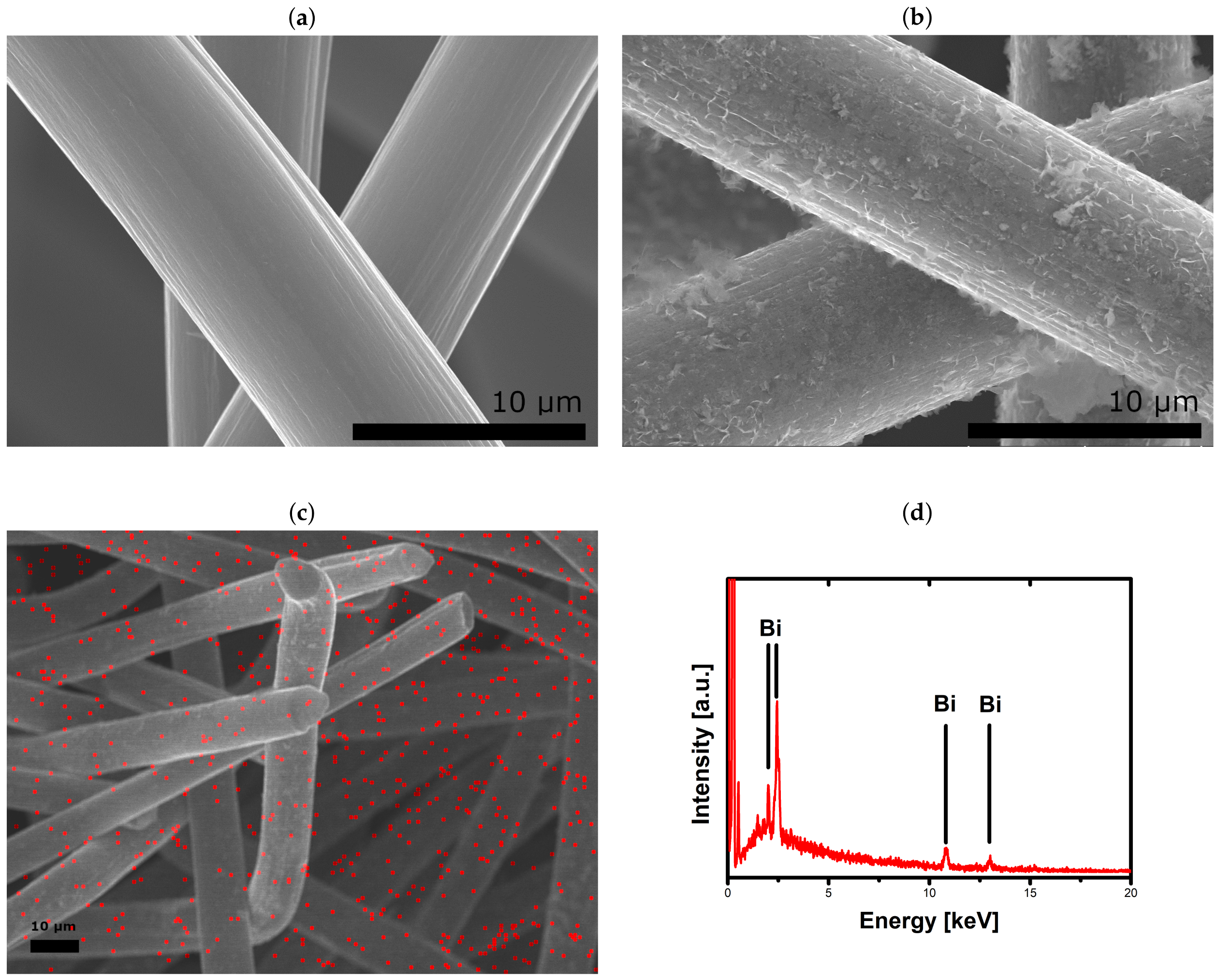
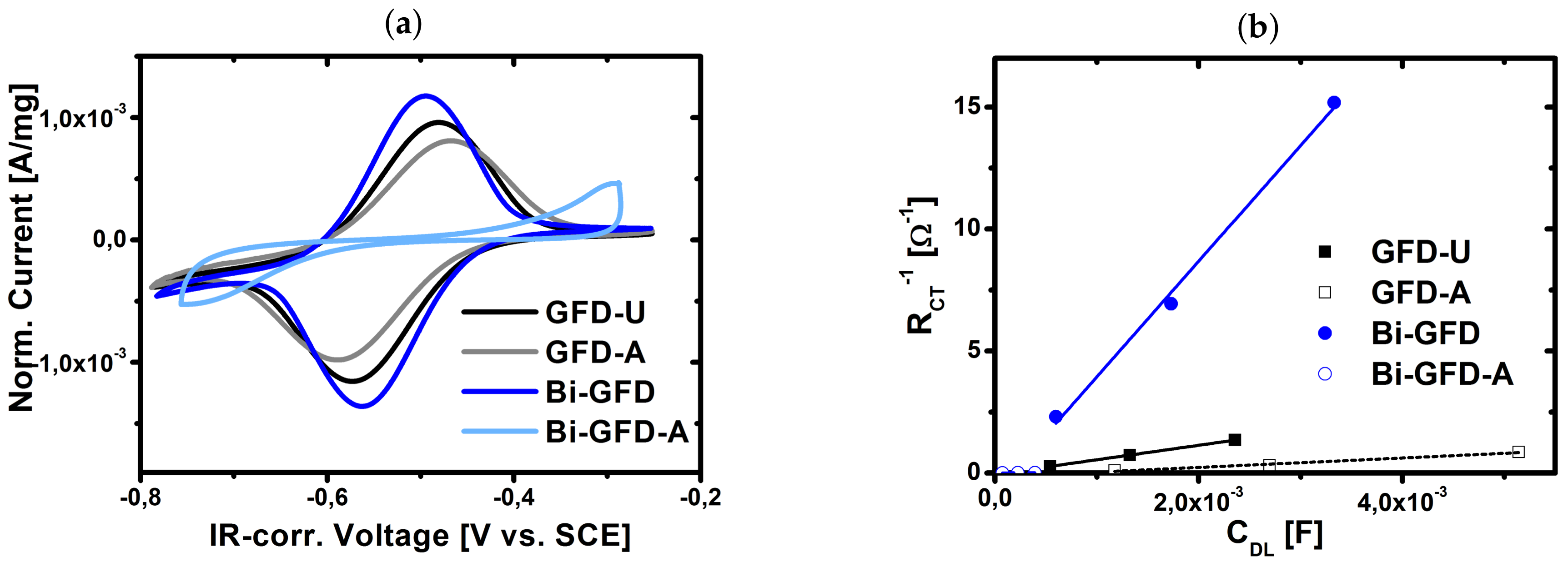
2.1. Catalytic Activity of Bismuth

Carbon felt electrodes were modified with Bi2O3by a simple impregnation route. This involved soaking felts in acidic bismuth nitrate solution, precipitating with ammonia and heat treatment at 300 Cunder N 2 -atmosphere (Bi-GFD). To relate any observed change in electrochemical activity for the V(II)/V(III)redox reactiononly to the presence of bismuth and to rule out any influence of the applied acidic, alkaline and temperature conditions, further felts were prepared as a reference. Felts subjected to first acidic and then alkaline media were labeled as GFD-Ref, felts heat-treated afterwards as GFD-Ref-HT. Felts only heat-treated were labeled GFD-HT, while untreated felts are referred to as GFD-U.
Figure 1 shows scanning electron microscopy (SEM) images of untreated and Bi-modified felts. While for GFD-U (Figure 1a) the fibers exhibit a smooth surface, in the case of Bi-GFD (Figure 1b) they are covered by evenly distributed flakes. The energy dispersive X-ray (EDX) elemental mapping in Figure 1c as well as the according spectrum in Figure 1d clearly show the presence of bismuth in these particles [38]. The chosen impregnation route is therefore well suited for the preparation of Bi-modified carbon felt electrodes.
Electrochemical activity of modified felt electrodes for the V(II)/V(III)redox reactionwas evaluated by CV and EIS. Prior to each measurement, electrode samples have been wetted by centrifugation to give reproducible results. Reproducibility was checked for GFD-U (results not shown). In the CV measurements (Figure 2a), Bi-GFD shows an enhanced activity compared to GFD-U, which manifests in reduced peak separation and increased peak currents. Also, no significant differences in the CV response of GFD-U and the reference felts GFD-Ref, GFD-Ref-HT and GFD-HT are observed. However, Nyquist plots in Figure 2b indicate enhanced performance not only for Bi-GFD, but (less pronounced) also for all samples subjected to any treatment procedure. This can be seen from reduced diameters of the displayed semicircles, which is similar to reduced RCT values. As was pointed out earlier, a discussion of RCT without taking into account the wetted surface area does not allow for a comparison of electrode kinetics. Since the EIS response of porous carbon electrodes is highly sensitive to any changes of the wetted surface area [34], it must be clarified, whether the displayed differences are due to altered wetting behavior or to altered kinetics. Therefore, EIS was conducted on electrode samples of varying size. In Figure 2c this is shown exemplarily for untreated samples (GFD-U). The diameters of the semicircles displayed in the Nyquist plot expectedly decrease with increasing sample diameter. EIS data were fitted in a frequency range between 10 4 –1 Hz using a simple model, consisting of an ohmic resistance Rohm connected in series to a parallel combination of charge transfer resistance RCT and double layer capacity CDL: Rohm − (RCT|CDL). Following the aforementioned approach of Friedl and co-workers [35,36,37], the inverse RCT was plotted over CDL (Figure 2d). Fitting of the curves yields a linear relation for all samples under investigation. As was pointed out earlier, the slopes of the linear fits are direct measures for the exchange current density j 0 . Barely any deviation of these slopes was observed for electrodes, which did not contain bismuth. This means that the differences observed in Figure 2b are solely due to changes in wetting behavior and not related to altered kinetic properties. In contrast to that, Bi-GFD shows a significantly higher slope compared to all other samples. This demonstrates not only the catalytic activity of bismuth for the V(II)/V(III)redox reaction, but also shows that any possible performance gains for bismuth-modified electrodes can be attributed exclusively to the presence of bismuth, not to treatment conditions during bismuth deposition.

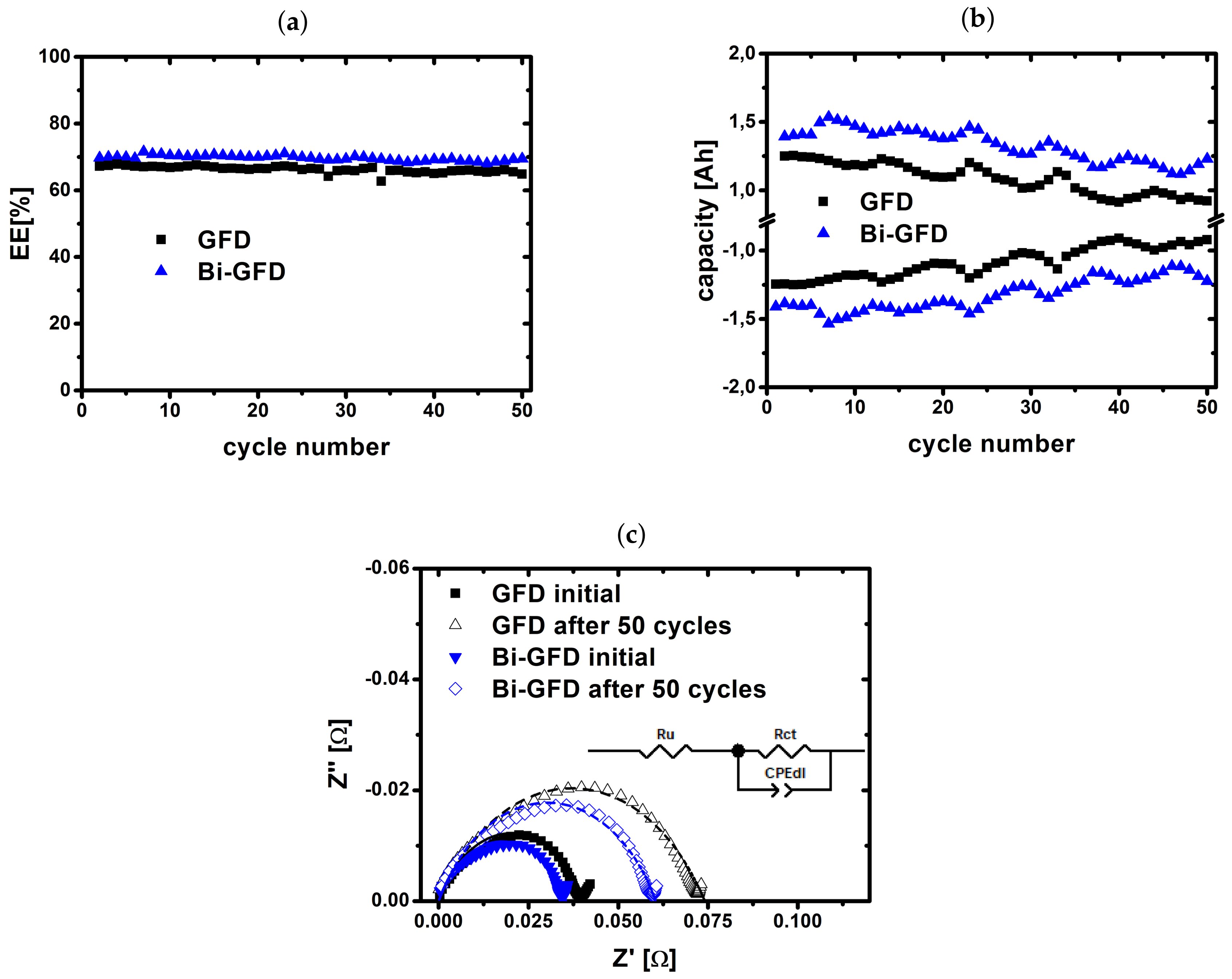
2.2. Charge/Discharge Cycling

To study the degradation behavior of bismuth-modified carbon felt electrodes under real working conditions, single cell battery charge/discharge cycling was performed. Cells employing either bismuth-modified (Bi-GFD) or untreated (GFD-U) felts as electrode at the negative half-cell have been cycled 50 times at a current density of 100 mA/cm 2 within the voltage limits of 1.65 V for charging and 0.8 V for discharging, respectively. Over the course of this experiment, in both cases a stable cell performance in terms of energy efficiency (EE) was obtained, as can be seen from Figure 3a. For Bi-GFD, a slightly higher EE (around 70%) was realized compared to GFD-U (around 66%). Also, the achieved capacities (Figure 3b) are permanently higher for Bi-GFD. Based on the results shown in the previous section, this had to be expected. Due to the catalytic activity of Bi, the overpotential for the V(II)/V(III)redox reactionis lowered, resulting in a wider SOC window being accessible during both charging and discharging, before the voltage limits are exceeded. However, over 50 cycles the capacity is fading in a similar fashion as for the cell employing GFD-U. Prior to and subsequent to the cycling, full cell EIS was conducted. The results are shown in Figure 3c. It is apparent that Bi-GFD shows lower impedance than GFD-U both before and after cycling. Fitting the data to a model Rohm − (RCT|CPE) reveals a similar decrease in CDL of around 38% for both cases (see Table 1). The increase in RCT is also comparable while slightly less distinct for Bi-GFD (77%) than for GFD (88%).
These findings indicate that Bi-modification of carbon felt electrodes is not able to prevent electrode degradation, since the loss of active surface area, manifested in the loss of CDL, is similar for both unmodified and bismuth-modified electrodes. Furthermore, a total reflection X-ray fluorescence (TXRF) spectroscopic investigation of the electrolyte gives strong evidence that bismuth is not stable on the fibers during cycling. After 50 cycles, the bismuth content of the electrolyte in the negative half-cell was determined to be 170 μ g/L. It seems therefore very likely that a leaching of catalyst occurred throughout operation of the cell. The nevertheless stable cell performance is in good agreement with Li et al. [27], who found an enhancing effect already, when bismuth was added to the electrolyte.

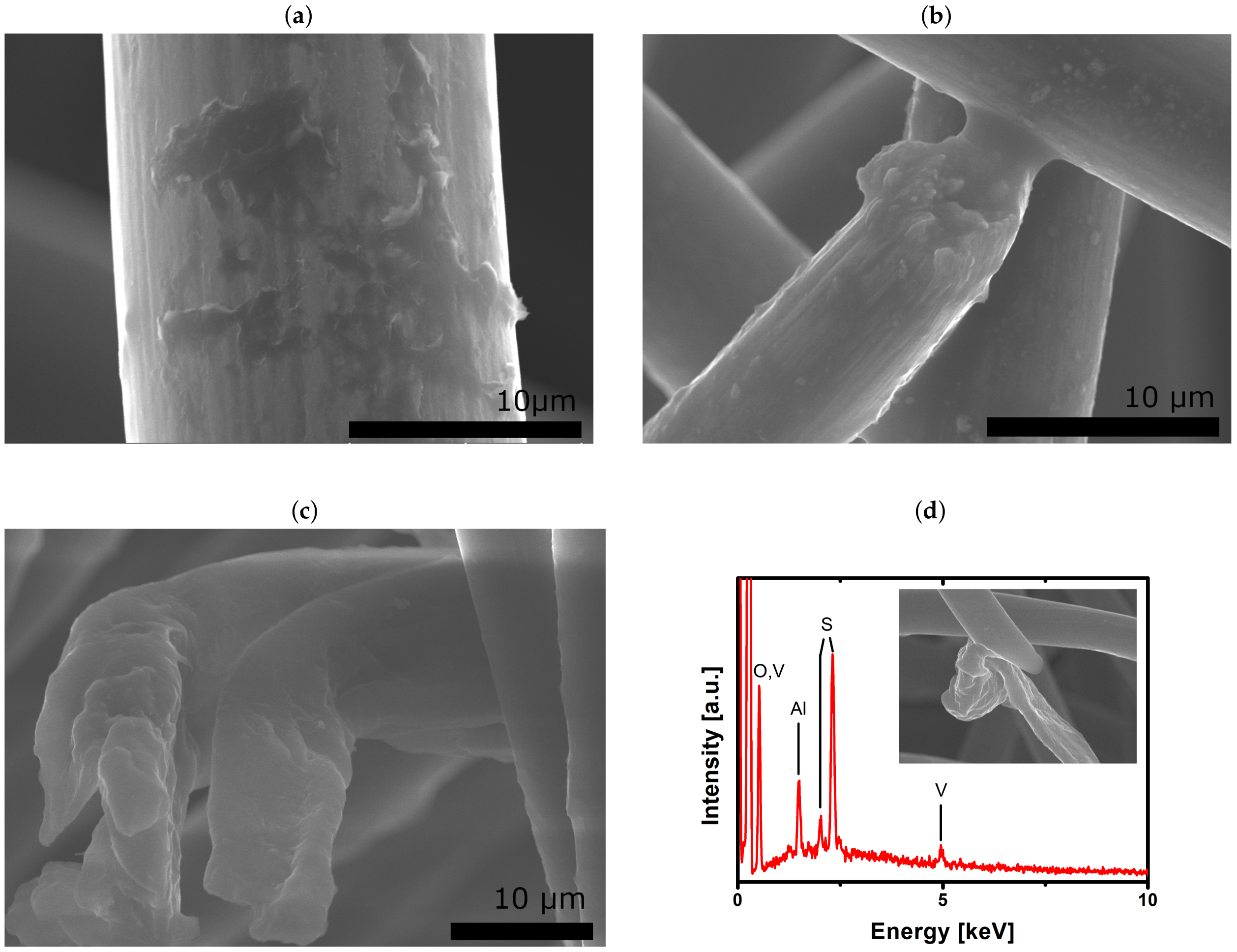
2.3. Evaluation of Aged Electrodes

Following the cycling experiment, the used electrodes were again evaluated in a similar fashion as before cycling, to study the effect of electrode degradation on the kinetics of the V(II)/V(III)redox reaction in a three-electrode setup. While GFD shows a reduced performance, apparent from reduced peak currents in Figure 4a and a less steep slope in Figure 4b, Bi-GFD seems to be completely deactivated after cycling. The CV shows no apparent redox peaks for Bi-GFD-A and the according kinetic slope practically equals 0. These results are to a certain extent surprising because even if the bismuth was removed from the fibers during cycling, as implicated by the TXRF results, a remaining performance at least comparable with that of GFD-U would have been expected. This being not the case indicates that a modification of carbon felt electrodes with bismuth may enhance kinetics if bismuth is present in the system, either on the electrode or at least in the electrolyte. However, on the other hand it seems likely that the presence of bismuth has a strong accelerating effect on the degradation of carbon fibers, leaving a completely deactivated electrode as soon as the bismuth is removed from the system. The SEM images in Figure 5 support this assumption. GFD-A (Figure 5a) shows agglomeration of material on the fiber surface with the overall fiber structure still being intact, whereas the fibers of Bi-GFD-A (exemplarily shown in Figure 5b,c) appear heavily corroded with the latter being so damaged that it appears to be split in half. To the best of our knowledge, this is the first time such phenomena have been observed for bismuth-modified electrodes in VRFB. Furthermore, in the EDX spectrum shown in Figure 5d no bismuth could be detected. Instead the spectrum shows peaks that can be attributed to vanadium, sulfur, and oxygen [38], which presumably originate from the electrolyte. The aluminum signal most probably originated from the used sample holder. However, since EDX is a local probe with bulk characteristics, no general conclusion can be drawn from this spectrum. Still, together with the TXRF results it supports the assumption that bismuth is not stable on the fibers during cycling. At the moment, the results presented herein cannot be explained. Further studies are needed to gain a deeper understanding of how the presence of bismuth affects the degradation of the carbon fibers.

3. Conclusions

In this study, carbon felt electrodes have been successfully modified with bismuth and studied in the negative half-cell reaction of VRFB. By a normalization of EIS results obtained in a three-electrode setup the catalytic properties of bismuth could be demonstrated. It was possible to attribute enhanced kinetic properties of modified electrodes to bismuth alone and to rule out any possible influence of the applied treatment methods. For the first time, bismuth-modified electrodes have been further subjected to electrochemical stress in a battery tester and afterwards evaluated again in a three-electrode setup. The results indicate that the presence of bismuth may have an accelerating effect on the degradation of carbon fibers even though the activity in the system tests was retained over 50 cycles. Further studies will be needed to explain these unexpected findings.

4. Materials and Methods

Unless otherwise stated, all chemicals were used as-received without any further purification.

4.1. Electrode Preparation

Carbon felts (GFD4.6; SGL Carbon, Meitingen, Germany) were immersed into a solution of 1 g Bismuth(III) nitrate hydrate (99.999% metals basis, Alfa Aesar, Heysham, UK) in 100 mL 5% acetic acid (Fisher Scientific, Loughborough, UK). After two days the soaked felts were removed and placed inside a 1 M aqueous solution of ammonium hydroxide (Carl Roth, Karlsruhe, Germany) for one more day. Subsequently, the impregnated felts were rinsed with deionized water (Merck Millipore, Darmstadt, Germany), dried over night at 80 C and finally heat-treated for 3 h at 300 C under N 2 -atmosphere to yield Bi-GFD.
For comparison, further felts underwent a similar preparation procedure, but without the presence of any bismuth salts: GFD-Ref (stored in 5% acetic acid for two days, then in 1 M ammonia for one day, no heat treatment), GFD-Ref-HT (like GFD-Ref, followed by heat treatment for 3 h at 300 C), GFD-HT (pristine felt, heat-treated under aforementioned conditions). Untreated carbon felts were labeled as GFD-U.

4.2. Electrode Characterization

Surface morphology and composition of the samples have been probed using a HITACHI UHR FE-SEM SU8030 ultrahigh-resolution scanning electron microscope which was operating at 20 kV acceleration voltage and coupled with an EDX spectrometer.
Quantification of bismuth was done by TXRF spectroscopy using a BRUKER S2 PicoFox device. Ga(NO 3 ) 3 (Merck CertiPUR) was added to the sample as an internal standard. A drop of the mixture was applied to a silicon-coated quartz glass sample plate and allowed to dry before initiation of TXRF measurements.

4.3. Electrode Aging

Aging of electrodes was performed by subjecting them to prolonged charge/discharge cycling in a battery test system (857 Redox Flow Cell Test System; Scribner Associates, Southern Pines, NC, USA). A 10 cm 2 flow through Micro Flow Cell (Electrocell A/S, Tarm, Danmark), equipped with an anion exchange membrane (FAP 450; Fumatech, Bietigheim-Bissingen, Germany) and graphite plates (FU 4369 HT; Schunk Kohlenstofftechnik, Heuchelheim, Germany) as current collectors, was used. Electrodes employed at the positive side were GFD-U in all cases. At the negative side either GFD-U or Bi-GFD was used. Upon installation, the electrodes were compressed by 17%. 70 mL commercial 1.6 M vanadium electrolyte (batch-no: 207445; GfE Gesellschaft für Elektrometallurgie mbH, Nürnberg, Germany) per side were pumped at a flow-rate of 25 mL min 1 . A constant nitrogen flow was applied to keep the system under inert conditions. Cycling experiments were performed at a constant current density of 100 mA cm 2 within the voltage limits of 1.65 V and 0.8 V for charging and discharging, respectively. Each cell was charged and discharged 50 times. Before and after cycling, full cell electrochemical impedance measurements (EIS) were performed at an open circuit potential (OCP) of 1.4 V (corresponding to a SOC of 50% [40,41]), using a potentiostat Reference 3000 (Gamry Instruments, Warminster, PA, USA). An AC voltage of 10 mV was applied in a frequency range from 10 5 –10 1 Hz.
Following a cycling experiment, the system was drained from electrolyte and washed with 3 M sulfuric acid (Carl Roth). The cell was then disassembled and the electrodes from the negative side were rinsed with deionized water and dried at 80 C before further assessment in a three-electrode-setup (see below). Aged electrodes obtained this way were labeled as either GFD-A or Bi-GFD-A.

4.4. Three-Electrode Measurements

Measurements in three-electrode setup were performed using a Gamry Reference 600 potentiostat. The electrolyte was a 0.16 M V2+/V3+(SOC 50%) solution obtained by dilution of pre-charged commercial electrolyte with 2M H2SO4. A Pt mesh served as counter electrode while a saturated calomel electrode (SCE) with a potential of +248 mV vs. SHE was used as reference electrode. Carbon felts of three different sizes were studied. From the samples of interest, pieces with 4, 6 or 8 mm diameter were punched out using appropriate punching irons. Prior to measurement, each felt was centrifuged in 5mL electrolyte for 5 min at 9500 rotations per minute to ensure proper wetting. Afterwards the felt was contacted by piercing it with a glassy carbon (GC) rod and used as the working electrode. The setup was kept under N 2 atmosphere during all measurements.
CV measurements were performed at a scan rate of 1 mV s 1 within the scan limits of −0.3 and −0.8 V vs. SCE. Since no stable OCP could be reached, start and end potential were set to be −0.5 V vs. SCE. This is in good agreement with the expected OCP value of a 1:1-mixture of V2+and V3+. Typically, three cycles were measured, from which the second was analyzed.
In the same setup, potentiostatic EIS experiments were conducted in a frequency range of 10 5 –10 1 Hz using an AC amplitude of 10 mV. The DC potential was set to be −0.5 V vs. SCE and the working electrode was conditioned at this potential for 5 min prior to the measurement.

Author Contributions

Conceptualization, J.S., I.D. and C.R.; Data curation, J.S.; Formal analysis, J.S. and G.A.E.-N.; Funding acquisition, C.R.; Investigation, J.S., E.B., G.A.E.-N., M.G. and P.K.; Methodology, J.S., M.S. and A.F.; Project administration, C.R.; Resources, C.R.; Supervision, C.R.; Validation, J.S.; Visualization, J.S.; Writing—original draft, J.S.; Writing—review & editing, C.R.

Funding

Financial support by BMWi project 03ET6129C is gratefully acknowledged.

Conflicts of Interest

The authors declare no conflict of interest.

List of Symbols

ϵ 0 permittivity of the free space
ϵ r relative dielectric permittivity
A w e t wetted surface area
C D L double layer capacitance
FFaraday constant
j 0 exchange current density
nnumber of electrons
Rgas constant
R C T charge transfer resistance
Tabsolute temperature
Z real part of the impedance
Z imaginary part of the impedance

References

  1. Alotto, P.; Guarnieri, M.; Moro, F. Redox flow batteries for the storage of renewable energy: A review. Renew. Sustain. Energy Rev. 2014, 29, 325–335. [Google Scholar] [CrossRef]
  2. Pan, F.; Wang, Q. Redox species of redox flow batteries: A review. Molecules 2015, 20, 20499–20517. [Google Scholar] [CrossRef] [PubMed]
  3. Noack, J.; Roznyatovskaya, N.; Herr, T.; Fischer, P. The Chemistry of Redox-Flow Batteries. Angew. Chem. Int. Ed. 2015, 54, 9776–9809. [Google Scholar] [CrossRef]
  4. Weber, A.Z.; Mench, M.M.; Meyers, J.P.; Ross, P.N.; Gostick, J.T.; Liu, Q. Redox flow batteries: A review. J. Appl. Electrochem. 2011, 41, 1137–1164. [Google Scholar] [CrossRef]
  5. Skyllas-Kazacos, M. New All-Vanadium Redox Flow Cell. J. Electrochem. Soc. 1986, 133, 1057. [Google Scholar] [CrossRef]
  6. Agar, E.; Dennison, C.R.; Knehr, K.W.; Kumbur, E.C. Identification of performance limiting electrode using asymmetric cell configuration in vanadium redox flow batteries. J. Power Sources 2013, 225, 89–94. [Google Scholar] [CrossRef]
  7. Sun, C.N.; Delnick, F.M.; Aaron, D.S.; Papandrew, A.B.; Mench, M.M.; Zawodzinski, T.A. Probing Electrode Losses in All-Vanadium Redox Flow Batteries with Impedance Spectroscopy. ECS Electrochem. Lett. 2013, 2, A43–A45. [Google Scholar] [CrossRef]
  8. Langner, J.; Melke, J.; Ehrenberg, H.; Roth, C. Determination of Overpotentials in All Vanadium Redox Flow Batteries. ECS Trans. 2014, 58, 1–7. [Google Scholar] [CrossRef]
  9. Langner, J.; Bruns, M.; Dixon, D.; Nefedov, A.; Wöll, C.; Scheiba, F.; Ehrenberg, H.; Roth, C.; Melke, J. Surface properties and graphitization of polyacrylonitrile based fiber electrodes affecting the negative half-cell reaction in vanadium redox flow batteries. J. Power Sources 2016, 321, 210–218. [Google Scholar] [CrossRef]
  10. Derr, I.; Bruns, M.; Langner, J.; Fetyan, A.; Melke, J.; Roth, C. Degradation of all-vanadium redox flow batteries (VRFB) investigated by electrochemical impedance and X-ray photoelectron spectroscopy: Part 2 electrochemical degradation. J. Power Sources 2016, 325, 351–359. [Google Scholar] [CrossRef]
  11. Noack, J.N.; Vorhauser, L.; Pinkwart, K.; Tuebke, J. Aging Studies of Vanadium Redox Flow Batteries. ECS Trans. 2011, 33, 3–9. [Google Scholar] [CrossRef]
  12. Pezeshki, A.M.; Sacci, R.L.; Veith, G.M.; Zawodzinski, T.A.; Mench, M.M. The Cell-in-Series Method: A Technique for Accelerated Electrode Degradation in Redox Flow Batteries. J. Electrochem. Soc. 2015, 163, A5202–A5210. [Google Scholar] [CrossRef]
  13. Derr, I.; Fetyan, A.; Schutjajew, K.; Roth, C. Electrochemical analysis of the performance loss in all vanadium redox flow batteries using different cut-off voltages. Electrochim. Acta 2017, 224, 9–16. [Google Scholar] [CrossRef]
  14. Derr, I.; Przyrembel, D.; Schweer, J.; Fetyan, A.; Langner, J.; Melke, J.; Weinelt, M.; Roth, C. Electroless chemical aging of carbon felt electrodes for the all-vanadium redox flow battery (VRFB) investigated by Electrochemical Impedance and X-ray Photoelectron Spectroscopy. Electrochim. Acta 2017, 246, 783–793. [Google Scholar] [CrossRef]
  15. Nibel, O.; Taylor, S.M.; Pătru, A.; Fabbri, E.; Gubler, L.; Schmidt, T.J. Performance of Different Carbon Electrode Materials: Insights into Stability and Degradation under Real Vanadium Redox Flow Battery Operating Conditions. J. Electrochem. Soc. 2017, 164, A1608–A1615. [Google Scholar] [CrossRef]
  16. Sun, C.N.; Delnick, F.M.; Baggetto, L.; Veith, G.M.; Zawodzinski, T.A., Jr. Hydrogen evolution at the negative electrode of the all-vanadium redox flow batteries. J. Power Sources 2014, 248, 560–564. [Google Scholar] [CrossRef]
  17. Schweiss, R.; Pritzl, A.; Meiser, C. Parasitic Hydrogen Evolution at Different Carbon Fiber Electrodes in Vanadium Redox Flow Batteries. J. Electrochem. Soc. 2016, 163, A2089–A2094. [Google Scholar] [CrossRef]
  18. Fetyan, A.; El-Nagar, G.A.; Lauermann, I.; Schnucklake, M.; Schneider, J.; Roth, C. Detrimental role of hydrogen evolution and its temperature-dependent impact on the performance of vanadium redox flow batteries. J. Energy Chem. 2018. [Google Scholar] [CrossRef]
  19. Park, M.; Ryu, J.; Cho, J. Nanostructured Electrocatalysts for All-Vanadium Redox Flow Batteries. Chem. Asian J. 2015, 10, 2096–2110. [Google Scholar] [CrossRef]
  20. Zhou, H.; Xi, J.; Li, Z.; Zhang, Z.; Yu, L.; Liu, L.; Qiu, X.; Chen, L. CeO2 decorated graphite felt as a high-performance electrode for vanadium redox flow batteries. RSC Adv. 2014, 4, 61912–61918. [Google Scholar] [CrossRef]
  21. Tseng, T.M.; Huang, R.H.; Huang, C.Y.; Hsueh, K.L.; Shieu, F.S. Improvement of titanium dioxide addition on carbon black composite for negative electrode in vanadium redox flow battery. J. Electrochem. Soc. 2013, 160, A1269–A1275. [Google Scholar] [CrossRef]
  22. Tseng, T.M.; Huang, R.H.; Huang, C.Y.; Liu, C.C.; Hsueh, K.L.; Shieu, F.S. Carbon Felt Coated with Titanium Dioxide/Carbon Black Composite as Negative Electrode for Vanadium Redox Flow Battery. J. Electrochem. Soc. 2014, 161, A1132–A1138. [Google Scholar] [CrossRef]
  23. Fetyan, A.; El-Nagar, G.A.; Derr, I.; Kubella, P.; Dau, H.; Roth, C. A neodymium oxide nanoparticle-doped carbon felt as promising electrode for vanadium redox flow batteries. Electrochim. Acta 2018, 268, 59–65. [Google Scholar] [CrossRef]
  24. Shen, J.; Liu, S.; He, Z.; Shi, L. Influence of antimony ions in negative electrolyte on the electrochemical performance of vanadium redox flow batteries. Electrochim. Acta 2015, 151, 297–305. [Google Scholar] [CrossRef]
  25. Li, B.; Gu, M.; Nie, Z.; Wei, X.; Wang, C.; Sprenkle, V.; Wang, W. Nanorod Niobium Oxide as Powerful Catalysts for an All Vanadium Redox Flow Battery. Nano Lett. 2014, 14, 158–165. [Google Scholar] [CrossRef] [PubMed]
  26. Kim, M.; Yoo, H.; Lee, G.; Choi, J. Enhanced VRB electrochemical performance using tungsten as an electrolyte additive. Electrochim. Acta 2017, 246, 190–196. [Google Scholar] [CrossRef]
  27. Li, B.; Gu, M.; Nie, Z.; Shao, Y.; Luo, Q.; Wei, X.; Li, X.; Xiao, J.; Wang, C.; Sprenkle, V.; Wang, W. Bismuth nanoparticle decorating graphite felt as a high-performance electrode for an all-vanadium redox flow battery. Nano Lett. 2013, 13, 1330–1335. [Google Scholar] [CrossRef]
  28. Suarez, D.J.; Gonzalez, Z.; Blanco, C.; Granda, M.; Menendez, R.; Santamaria, R. Graphite Felt Modified with Bismuth Nanoparticles as Negative Electrode in a Vanadium Redox Flow Battery. ChemSusChem 2014, 7, 914–918. [Google Scholar] [CrossRef]
  29. Liu, T.; Li, X.; Nie, H.; Xu, C.; Zhang, H. Investigation on the effect of catalyst on the electrochemical performance of carbon felt and graphite felt for vanadium flow batteries. J. Power Sources 2015, 286, 73–81. [Google Scholar] [CrossRef]
  30. Wei, G.; Fan, X.; Liu, J.; Yan, C. Electrospun carbon nanofibers/electrocatalyst hybrids as asymmetric electrodes for vanadium redox flow battery. J. Power Sources 2015, 281, 1–6. [Google Scholar] [CrossRef]
  31. Lv, Y.; Zhang, J.; Lv, Z.; Wu, C.; Liu, Y.; Wang, H.; Lu, S.; Xiang, Y. Enhanced electrochemical activity of carbon felt for V 2+ /V 3+ redox reaction via combining KOH-etched pretreatment with uniform deposition of Bi nanoparticles. Electrochim. Acta 2017, 253, 78–84. [Google Scholar] [CrossRef]
  32. Yang, X.; Liu, T.; Xu, C.; Zhang, H.; Li, X.; Zhang, H. The catalytic effect of bismuth for VO 2 + /VO 2+ and V 3+ /V 2+ redox couples in vanadium flow batteries. J. Energy Chem. 2017, 26, 1–7. [Google Scholar] [CrossRef]
  33. Liu, Y.; Liang, F.; Zhao, Y.; Yu, L.; Liu, L.; Xi, J. Broad temperature adaptability of vanadium redox flow battery–part 4: Unraveling wide temperature promotion mechanism of bismuth for V 2+ /V 3+ couple. J. Energy Chem. 2018. [Google Scholar] [CrossRef]
  34. Goulet, M.A.; Skyllas-Kazacos, M.; Kjeang, E. The importance of wetting in carbon paper electrodes for vanadium redox reactions. Carbon 2016, 101, 390–398. [Google Scholar] [CrossRef]
  35. Friedl, J.; Bauer, C.M.; Rinaldi, A.; Stimming, U. Electron transfer kinetics of the – Reaction on multi-walled carbon nanotubes. Carbon 2013, 63, 228–239. [Google Scholar] [CrossRef]
  36. Fink, H.; Friedl, J.; Stimming, U. Composition of the Electrode Determines Which Half-Cell’s Rate Constant is Higher in a Vanadium Flow Battery. J. Phys. Chem. C 2016, 120, 15893–15901. [Google Scholar] [CrossRef]
  37. Friedl, J.; Stimming, U. Determining Electron Transfer Kinetics at Porous Electrodes. Electrochim. Acta 2017, 227, 235–245. [Google Scholar] [CrossRef]
  38. Bruker. Periodic Table of Elements and X-ray Energies; Bruker: Billerica, MA, USA, 2018. [Google Scholar]
  39. Hirschorn, B.; Orazem, M.E.; Tribollet, B.; Vivier, V.; Frateur, I.; Musiani, M. Determination of effective capacitance and film thickness from constant-phase-element parameters. Electrochim. Acta 2010, 55, 6218–6227. [Google Scholar] [CrossRef]
  40. Wei, Z.; Lim, T.M.; Skyllas-Kazacos, M.; Wai, N.; Tseng, K.J. Online state of charge and model parameter co-estimation based on a novel multi-timescale estimator for vanadium redox flow battery. Appl. Energy 2016, 172, 169–179. [Google Scholar] [CrossRef]
  41. Wei, Z.; Tseng, K.J.; Wai, N.; Lim, T.M.; Skyllas-Kazacos, M. Adaptive estimation of state of charge and capacity with online identified battery model for vanadium redox flow battery. J. Power Sources 2016, 332, 389–398. [Google Scholar] [CrossRef]
Figure 1. SEM images of fresh carbon felts: (a) untreated GFD-U, (b) bismuth-modified Bi-GFD and (c) elemental mapping for bismuth on Bi-GFD with (d) respective EDX spectrum.
Batteries 05 00016 g001
Figure 2. Measurements in three-electrode setup using differently modified carbon felt electrodes: (a) IR-corrected CV curves, given currents normalized by electrode weight; (b) Nyquist plots of modified carbon felts; (c) exemplary Nyquist plots of carbon felt with different diameters; (d) inverse charge transfer resistance plotted versus double layer capacity.
Batteries 05 00016 g002
Figure 3. Results of charge/discharge cycling in a battery test system: (a) energy efficiency; (b) capacity over 50 cycles of charging and discharging at 100 mA cm 2 ; (c) full cell EIS data before and after cycling.
Batteries 05 00016 g003
Figure 4. Evaluation of aged electrodes in three-electrode setup: CV (a) and normalized EIS results (b).
Batteries 05 00016 g004
Figure 5. SEM images of aged carbon felts: (a) unmodified GFD-A; (b,c) Bi-modified Bi-GFD-A; (d) EDX spectrum of Bi-GFD-A recorded at the spot shown in the inset.
Batteries 05 00016 g005
Table 1. Full Cell EIS parameters before and after 50 charge/discharge cycles at 100 mA/cm 2 . Values for CDL were obtained by conversion of CPE parameters following Hirschorn et al. [39].
RCT (m Ω )CDL (mF)
GFD initial40.95.37
GFD after 50 cycles76.73.35
Bi-GFD initial31.65.94
Bi-GFD after 50 cycles55.83.69

