Article

Mechanical Coating of Zinc Particles with Bi2O3-Li2O-ZnO Glasses as Anode Material for Rechargeable Zinc-Based Batteries

1
Department of Materials Processing, University of Bayreuth, 95447 Bayreuth, Germany
2
Department of Functional Materials, Zentrum für Energietechnik (ZET), University of Bayreuth, 95447 Bayreuth, Germany
*
Author to whom correspondence should be addressed.
Batteries 2018, 4(1), 12; https://doi.org/10.3390/batteries4010012
Submission received: 9 January 2018 / Revised: 5 February 2018 / Accepted: 15 February 2018 / Published: 23 February 2018

Abstract

:
The electrochemical performance of zinc particles with 250 μm and 30 μm diameters, coated with Bi2O3-Li2O-ZnO glass is investigated and compared with noncoated zinc particles. Galvanostatic investigations were conducted in the form of complete discharge and charging cycles in electrolyte excess. Coated 30 μm zinc particles provide the best rechargeability after complete discharge. The coatings reached an average charge capacity over 20 cycles of 113 mAh/g compared to the known zero rechargeability of uncoated zinc particles. Proposed reasons for the prolonged cycle life are effective immobilization of discharge products in the glass layer and the formation of percolating metallic bismuth and zinc phases, forming a conductive network through the glass matrix. The coating itself is carried out by mechanical ball milling. Different coating parameters and the resulting coating quality as well as their influence on the passivation and on the rechargeability of zinc–glass composites is investigated. Optimized coating qualities with respect to adhesion, homogeneity and compactness of the glass layer are achieved at defined preparation conditions, providing a glass coating content of almost 5 wt % for 250 μm zinc particles and almost 11 wt % for 30 μm zinc particles.

1. Introduction

In the course of global energy transition, the efficient use of renewable energy is indispensable. A major disadvantage of renewable energy sources, such as solar and wind, is their nonuniform current feed into the energy grid due to unsteady natural conditions. In order to avoid load peaks as well as bottlenecks in the power supply, energy storage devices are crucial to increase energy efficiency and availability inside the electrical grid [1,2]. In addition to commercially available electrically rechargeable batteries, such as lead–acid, nickel–cadmium, nickel–metal hydride, or lithium–ion batteries, the zinc–air battery is considered as a promising candidate due to its high specific energy (1350 Wh kg−1), good environmental compatibility, low cost, and safety [3,4,5,6,7,8]. However, a crucial disadvantage is its low cyclability. Thus, zinc–air batteries are mainly applied as primary batteries, e.g., in the form of button cells, which are, e.g., used in medical devices [3,9,10]. Beside the development of highly efficient bifunctional oxygen electrocatalysts on the cathode side [11], the degradation of the zinc anode is a major concern regarding rechargeability. The rechargeability of the zinc anode is limited due to dendritic growth, shape change, and self-discharge [12,13,14,15]. Additional degradation occurs due to passivation of the zinc electrode [16]. During discharge, zinc oxidizes and soluble zincate ions are formed, which leads to an electrically insulating Zn(OH)2 and ZnO layer [17]. The solubility of the zincate ions in the electrolyte is a key issue, as the ions migrate from the zinc surface towards the electrolyte, so that the diffusion path length during the recharge phase is significantly increased and their reduction becomes inefficient [18].
To overcome these problems, several methods such as composite addition, electrolyte modification, or surface treatment of zinc particles have been studied [19,20,21,22,23,24,25]. In particular, the addition of p-type electronically conductive Bi2O3 to the zinc electrode seems to be promising. It has already been shown in [18] that zincate ions can be deposited on Bi2O3 and precipitate into ZnO. As a result, zincate ions remain in the electrode as electrochemically active material and do not migrate to the electrolyte. Due to the formation of electronically percolated Bi paths inside the Bi2O3, the electrode becomes rechargeable [26].
In our previous work zinc particles were coated with pulverized Bi2O3-CaO-ZnO glass [27]. In that work, zinc particles have been mechanically coated in an agitator bead mill with Bi2O3-Li2O-ZnO glasses. By using a Bi2O3-Li2O-ZnO glass, the Bi2O3 content can be significantly increased compared to a Bi2O3-CaO-ZnO glass (40 mol % vs. 60 mol %). To obtain an amorphous, stable and swellable glass with such a high Bi2O3 content, however, the use of Li2O as a swellable glass component is necessary. Intermediate swelling in aqueous KOH solution coats the zinc particles with a glass-based gel layer [27]. The layer immobilizes the discharge products by physically blocking and creates an electrically conductive network based on Bi2O3. Thus, the discharge products are considered to be electrochemically accessible during a subsequent recharge phase. A schematic illustration of this concept is given in Figure 1.
The influence of different coating parameters and the resulting coating quality as well as their influence on the passivation and rechargeability of zinc–glass composites after complete discharge is investigated in this study. The coating is characterized by scanning electron microscope (SEM), inductively coupled plasma optical emission spectrometer (ICP-OES), and Brunauer-Emmett-Teller (BET) surface determination. Electrochemical analysis is conducted by galvanostatic cycling in a half-cell configuration in electrolyte excess. In addition, post-mortem analyses of the cycled zinc–glass composites are carried out by SEM and X-ray diffractometer (XRD).

2. Experimental Setup

2.1. Synthesis of Bi2O3-Li2O-ZnO Glass

Bi2O3 (Alfa Aesar GmbH & Co KG, 99.975%), ZnO (Alfa Aesar GmbH & Co KG, 99.99%), and Li2CO3 (Merck KGaA, <99.9%) were used as starting materials for the glass system Bi2O3-Li2O-ZnO. The composition of the glass is shown in Table 1.
The melting process was carried out in a high-temperature furnace (H108/17, Nabertherm GmbH, Lilienthal, Germany). Three 50 g glass batches were investigated. One batch was molten in an Al2O3 crucible at 1050 °C, and two batches were molten in a Pt crucible at 1050 °C and 1200 °C, respectively. The heating rate for all batches was 6 °C/min and the melting temperature was maintained for 30 min. Subsequently, the glass melt was cast on a copper plate and quenched by using copper stamps. The solidified glass plates were milled into powder in a planetary ball mill at 170 rpm for 30 min (Pulverisette 5, Fritsch GmbH, Idar-Oberstein, Germany) and then sieved into a fraction with a diameter of less than 63 μm.

2.2. Synthesis of Zinc–Glass Composite Material

Zinc particles from Grillo Werke AG (d50 = 250 μm; alloying agents analyzed by ICP-OES: Pb 516 ppm, In 306 ppm, Bi 301 ppm; BET surface area: 0.0197 m2 g−1) were used as raw material. The zinc particles were coated with the glasses by mechanical coating in an agitator bead mill (Simoloyer® CM01, Zoz GmbH, Wenden, Germany). The grinding container with a volume of 0.5 ltr. was filled with 35 vol % polyetheretherketone grinding balls (d = 5 mm). Rotational speed was varied (500 rpm, 750 rpm, and 1000 rpm), and grinding time was set to 15 and 30 min. The determined optimal coating parameters were transferred to finer zinc particles from Grillo Werke AG (d50 = 30 μm; alloying agents analyzed by ICP-OES: Pb 554 ppm, In 339 ppm, Bi 316 ppm; BET surface area: 0.0407 m2 g−1). The total zinc masses for course and fine particles were kept constant. The amount of glass powder was adapted in relation to the absolute surface area of zinc particles. The weight ratio of glass mass to zinc surface was set to 10.15 g m−2.

2.3. Analytical Methods

Structural properties of the glasses and the post cycled zinc glass composite materials were studied by the X-ray diffraction method (X’Pert-MPD System PW 3040/00, Philips Analytical X-Ray B.V., EA Almelo, The Netherlands). Diffraction patterns were acquired with Cu Kα radiation between scattering angles of 15° and 75° in increments of 0.02°. Additionally, SEM with energy dispersive X-ray spectroscopy (EDX) was used to analyze the crystallization behavior of the glasses and to evaluate the glass coating on the zinc particles before and after cycling (JSM-840A, JEOL, Tokyo, Japan; INCA 4.05 EDS, Oxford Instruments Microanalysis Limited, Abingdon, UK). For this purpose, the glasses and zinc particles were embedded in epoxy resin and cross sections were prepared. To determine the percentage of glass on zinc particles after the coating process, optical emission spectroscopy was used (ICP-OES Optima, PerkinElmer, Waltham, MA, USA). Coating quality was evaluated by measuring the thickness of the glass layer at seven points of the embedded zinc particles. The mean value and the standard deviation were calculated from these data. The BET surface area of as received zinc was measured by the nitrogen adsorption-desorption method (ASAP 2020, Micromeritics, Norcross, GA, USA).

2.4. Electrochemical Characterization

The electrochemical analysis of the anode composite materials was performed in a half-cell configuration (Potentiostat Bio-Logic, VMP3, Seyssinet-Pariset, France). 100 mg of active material was added to a copper conductor as powder bed. 6 M KOH in high excess (80 mL in a 100 mL glass beaker) was used as electrolyte. A platinum plate and an Ag/AgCl electrode (3.5 M KCl) were applied as counter and reference electrode. Before the first discharge, a swelling for 1 h was allowed. The anode was galvanostatically fully discharged up to a cell cut off voltage of U = −0.9 V vs. Ag/AgCl at a current rate of C/20 followed by a subsequent charge step up to a cell cut off voltage of U = −1.71 V vs. Ag/AgCl at the same current rate. The number of cycles has been set to 20.
Additionally, the passivation behavior of the particles was investigated by EIS measurements. An AC voltage (amplitude 20 mV) was applied in a frequency range from 20 mHz to 1 MHz. The internal resistance Ri was determined by the real part of the complex resistance in the Nyquist plot. The measurements were carried out before the first discharge, after the first discharge, and after the first recharge.

3. Results and Discussion

3.1. Optimization of Process Conditions of Bi2O3-Li2O-ZnO Glass

To study the influence of different crucibles and temperatures on the glass formation process, the solidified glasses were analytically examined after the melting process and the most suitable melting process was selected. Figure 2 shows the XRD analysis of the molten glass after melting in (a) an Al2O3 crucible at 1050 °C, (b) in a Pt crucible at 1050 °C, and (c) in a Pt crucible at 1200 °C.
Using an Al2O3 crucible at 1050 °C results in a partly crystalline structure with portions of Bi2O3 and ZnO (Figure 2 curve a). Using a Pt crucible results in a mainly amorphous structure with only few ZnO crystals (Figure 2 curve b), and at 1200 °C, no ZnO crystals can be found (Figure 2 curve c). These results are confirmed by SEM images of cross sections of the glasses as shown in Figure 3.
The glass that has been melted in the Al2O3 crucible at 1050 °C shows a high number of ZnO crystals with aluminum impurities as shown by spot S1 in Figure 3a. In a Pt crucible the number of ZnO crystals is reduced significantly (Figure 3b). The use of an Al2O3 crucible at such high temperatures causes an alumina leaching into the glass melt. The alumina impurities may serve as nuclei that cause a change in the nucleation rate and an increased crystallization in the subsequent quenching step.
After increasing the melting temperature to 1200 °C, only a few small ZnO crystals (EDX-analysis of spot S2 in Figure 3d) can be detected (Figure 3c) due to the almost complete dissolution of ZnO in the melt. Based on this, ZnO cannot act as a nucleus for crystallization. The latter procedure likely prevents an enhanced nucleation and crystal growth at those ZnO centers during discharge. Therefore, this synthesis procedure was selected for further coating experiments.

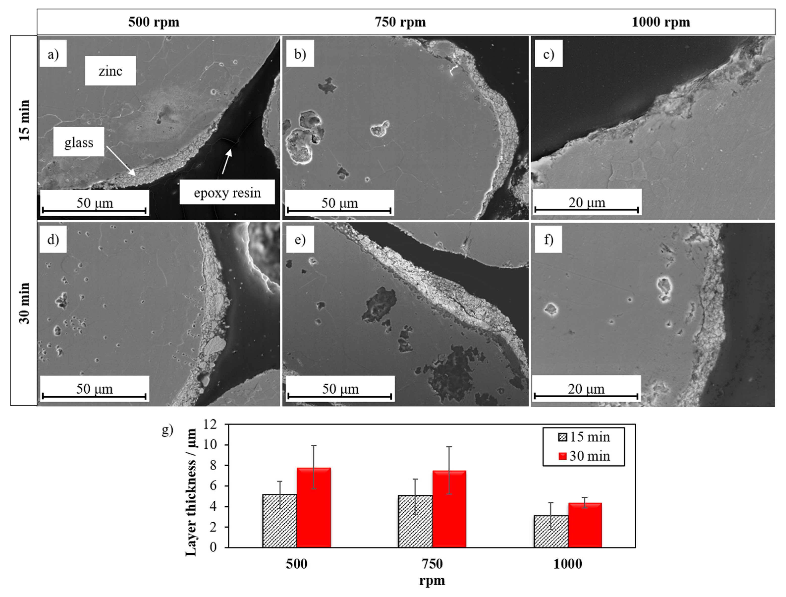
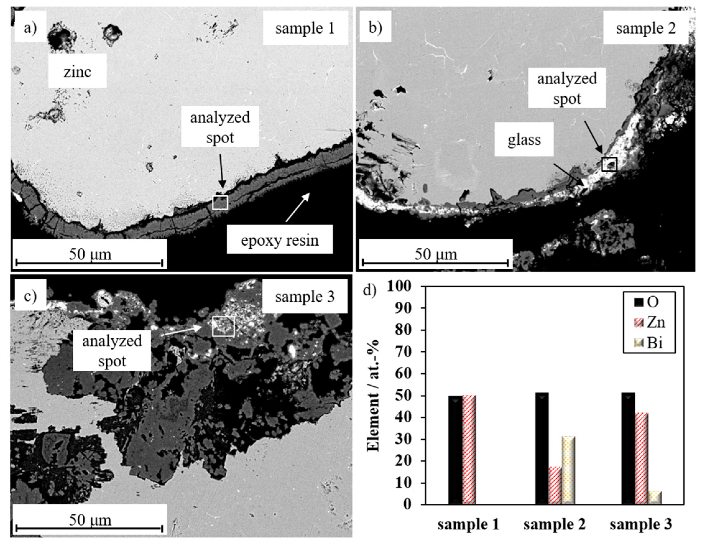
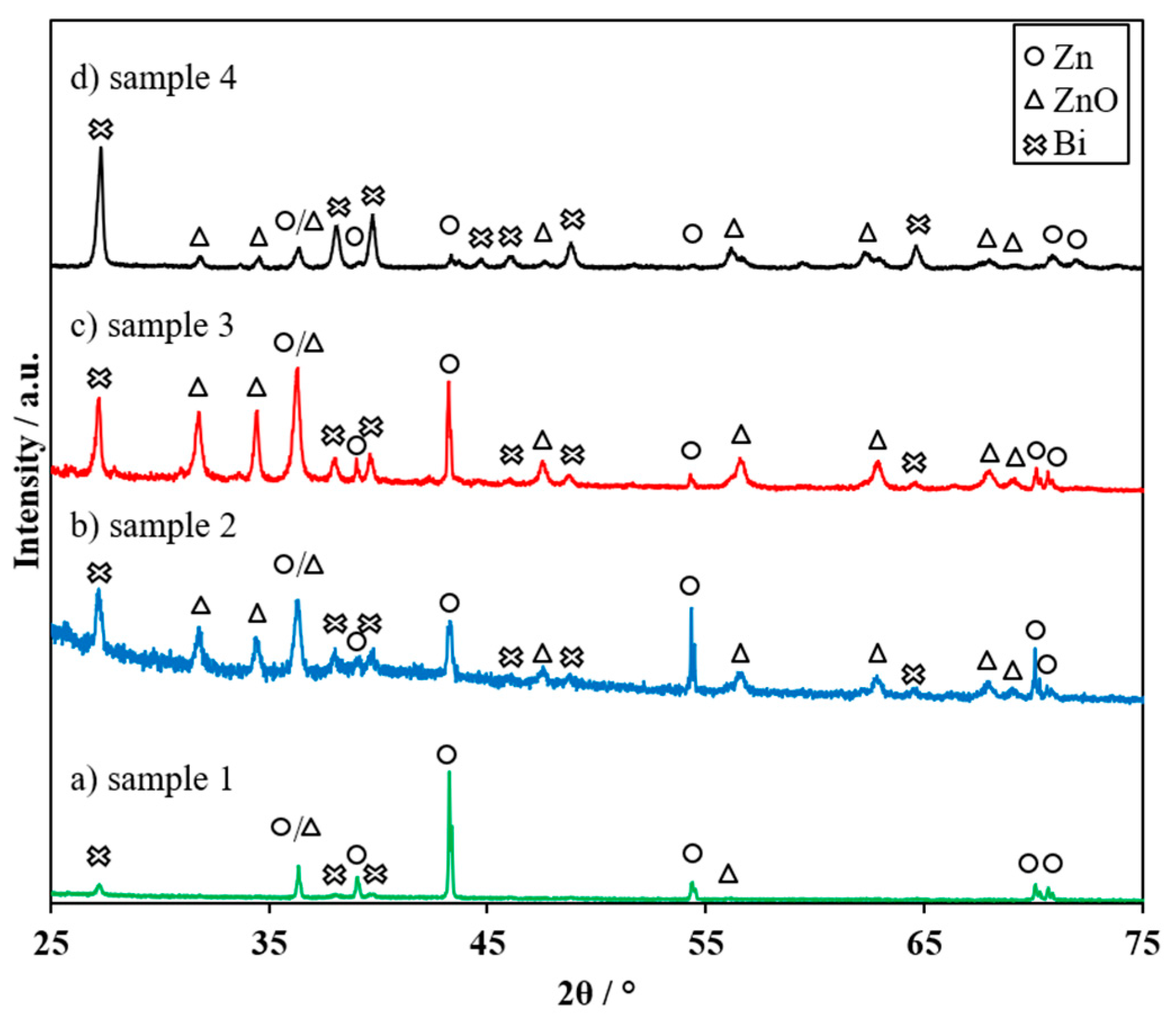
3.2. Optimization of the Coating Parameters for Zinc–Glass Composite Material

In order to optimize the coating quality of the zinc particles with the glass described in Section 3.1, a parameter variation of the mechanical coating process was applied. Figure 4 shows SEM micrographs of coated zinc particles (250 μm) and the corresponding layer thicknesses in cross section after 15 min and after 30 min coating time at either 500 rpm, 750 rpm or 1000 rpm, respectively.
An increase of rotational speed from 500 rpm to 750 rpm and 1000 rpm (Figure 4a–c) results in a more homogeneous and compact glass coating. The glass layer thickness is reduced from (5.1 ± 1.3) μm to (3.0 ± 1.3) μm at 15 min. (Figure 4g). Probably a stronger adhesion of the glass layer to the zinc particles is achieved due to the increased kinetic energy during milling. If the coating time is raised from 15 to 30 min (Figure 4d–f), a similar behavior can be seen. By increasing the speed of the rotor, the layer thickness decreases from (7.8 ± 2.1) μm at 500 rpm to (7.5 ± 2.1) μm at 750 rpm to (4.4 ± 0.5) μm at 1000 rpm (Figure 4g).
Doubling the coating time leads to an increase of the coating thickness of about 30–50% as is exemplarily confirmed by determination of the amount of glass (analyzed by ICP-OES) in Table 2 for sample 1 (1.61 wt %) and sample 3 (4.83 wt %) after coating. Due to the longer coating process and the increased number of collisions between grinding balls, zinc particles, and glass, more energy can be transferred into the system. This yields a higher coating content.
On the other hand, rotational speed increases compaction of the glass layer, as indicated, e.g., by sample 2 and sample 3. The amount of glass does not increase while the coating thickness decreases. By applying 1000 rpm for 30 min to fine zinc particles with d50 = 30 μm (see Table 2; sample 4), a strongly bonded glass layer with uniform thickness was achieved. The resulting content of glass is 10.72 wt % at an average layer thickness of 2 μm. The thinner glass layer of the coated fine zinc particles compared to the coated coarse zinc particles can be explained by the increased number of impact processes of the smaller zinc particles. Thus, a uniform thin layer is formed. The higher glass content (10.72 wt % instead of 4.83 wt %) of the fine zinc particles is attributed to the higher surface area of the fine zinc particles. This means that a higher glass coating content can be applied with approximately the same zinc surface coverage with glass (Table 2).

3.3. Electrochemical Performance

In order to investigate the influence of different coating contents, glass layer thicknesses, and particle sizes, selected zinc–glass composites (Table 2) were electrochemically investigated and compared with uncoated zinc powder. Figure 5 shows the results of the galvanostatic cycling of glass-coated 250 μm and 30 μm zinc particles (samples 1 to 4 listed in Table 2).
Uncoated zinc achieved a specific capacity of 596 mAh g−1 (Figure 5a) at the first discharge, while zinc–glass composites (sample 1 to 3) show a reduced specific capacity of 440 mAh g−1, 483 mAh g−1, and 462 mAh g−1, respectively (Figure 5a). The reduced discharge capacity of the zinc–glass composites is caused on the one hand by the mass reduction of active material itself, as the coating does not directly contribute to electrochemical discharge reactions. On the other hand, the accessibility of the hydroxide ions to the zinc surface is limited by the glass coating, thus the cut-off voltage is reached earlier during discharge.
Recharge of pure zinc powder is impossible (Figure 5b) due to the electrical passivation by the ZnO formation. The existence of an insulating ZnO layer can be confirmed by the increase in the internal resistance after the first discharge, which is shown in Table 3.
The internal resistance of pure Zn increases from 1.16 Ω to 9.08 Ω and remains at the same level after attempted charging. The same effect occurs in sample 1. We attribute it to the incomplete glass layer formation, which probably cannot prevent the formation of a compact insulating ZnO layer, as post-mortem characterizations of zinc particle cross sections indicate (Figure 6a; analyzed spot of sample 1). The internal resistance increases from 1.03 Ω to 11.29 Ω after the first discharge. Due to the low glass content, Ri decreases slightly to 6.30 Ω after the first incomplete recharge. Nevertheless, a passivated ZnO layer is formed and charging is not possible.
In contrast, a glass coating content of 4.39 wt % (Table 2; sample 2) allows recharging at a low level with a charge capacity of 32 mAh g−1 at the first cycle (Figure 5b). Ri increases from 1.18 Ω to 2.97 Ω after the first discharge. Due to the increased glass coating content, this increase is lower compared to sample 1, indicating decreased ZnO layer formation. It is assumed that zincate ions can be immobilized during the first discharge in the formed gel-like glass layer [27]. As a result, locally bound zincate ions can be utilized for charging and hence for subsequent discharge (Figure 5a). After the first recharge, Ri decreases to 1.32 Ω due to the reduced ZnO layer. However, zinc particles are completely passivated after three cycles and the rechargeability is lost. The SEM cross section in Figure 6b indicates that ZnO forms a dense layer under the glass coating (Figure 6b; analyzed spot of sample 2) and passivates the coated zinc particle.
In case of sample 3 with a thin and homogeneous glass layer, recharging is possible eight times with an improved charge capacity of 74 mAh g−1 at the first cycle (Figure 5b). Furthermore, sample 3 shows a low increase in internal resistance after the first discharge (Table 3; 1.14 Ω to 1.68 Ω) and only a slightly increased internal resistance after the first recharge (Table 3; 1.35 Ω) compared to the initial state. Due to the uniform, thin and compact glass layer of sample 3, a homogeneous gel coating is formed. It entraps the zincate ions close to the electrode, enabling improved cycle stability. Due to the progressive irreversible passivation of the electrode, recharging is only possible eight times. Nevertheless, in each cycle, the discharge capacity is higher than the previous charge capacity. This indicates that the formation of passivation layers on the glass-coated zinc particles is reduced and subsequent oxidation of zinc is maintained, as illustrated after charging step 9 where recharge stops, but discharging in cycle 10 is performed successfully (Figure 5). Then, a higher utilization of the zinc is achieved, which is confirmed by post-mortem analysis in Figure 6c. Improved recharging creates a sponge-like ZnO layer with an embedded Bi2O3-based glass layer (Figure 6c; analyzed spot of sample 3).
X-ray diffraction patterns of the charged cycled zinc–glass composites in Figure 7 indicate the existence of zinc oxide, metallic zinc, and rhombohedral metallic bismuth.
These Bi metal reflections have already been observed and discussed in the literature on zinc anodes with bismuth oxide [18,26,27]. Metallic bismuth enhances the electrical conductivity through the gel matrix and enables the zinc–glass composite (sample 2, sample 3, and sample 4) to be recharged.
In addition, Figure 5 illustrates the results of galvanostatic cycling of the coated fine zinc particles (sample 4) in comparison to sample 3. Sample 4 with a specific first discharge capacity of 561 mAh g−1 shows an increased first zinc utilization compared to sample 3 with 462 mAh g−1 (Figure 5a). This can be explained as follows: The fine zinc particle fraction has an increased specific surface area of 0.0407 m2 g−1 compared to 0.0197 m2 g−1 of the coarse zinc particle fraction. This allows more active material to participate in the electrochemical reactions, and thus considerably increases the first discharge capacity.
Recharging of sample 4 is possible with 82 mAh g−1 after the first discharge. The increase of the charging capacity in the following cycles up to 140 mAh g−1 in the fourth charging step is remarkable (Figure 5b). This can be justified by the enhanced formation of electrically conductive metallic bismuth paths (Figure 7d) owing to the increased glass content on fine zinc particles. (10.72 wt % compared to 4.83 wt % of coarse zinc particles). Due to the higher glass content and the compact Bi2O3-based glass layer of sample 4, a more stable glass-gel matrix with increased retention for zincate ions close to the electrode is proposed. In addition, smaller particles provide more contact points amongst each other and thus improve the electrical conductivity through the electrode/electrolyte matrix. Thus, passivation of the zinc particles is reduced and a discharge capacity of 52 mAh g−1 is achieved even in the 20th cycle (Figure 5a). The average charge capacity over 20 cycles is 113 mAh g−1.

4. Conclusions

The mechanical coating of zinc particles for rechargeable zinc–air batteries with glasses based on Bi2O3 as a network former reduced the passivation of zinc particles during discharging. The size of the coated zinc particles, the coating quality, and the compaction of the glass layer were the crucial factors. Optimized coating parameters with respect to adhesion and homogeneity of the glass layer resulted in a glass coating content of 4.83 wt % with a glass layer thickness of 4.4 μm at 250 μm zinc particles. During the discharge process, zincate ions were immobilized in the glass layer and reduced during the subsequent charging. Recharge was possible with a charge capacity of 74 mAh g−1 at the first cycle for the coated 250 μm zinc particles. Post-mortem analyses showed that the Bi2O3 content of the glass layer was reduced to metallic Bi paths. After 8 discharge cycles, rechargeability was lost, and SEM images showed the formation of a sponge-like ZnO and Bi2O3-based glass network with metal phases of Zn and Bi.
By using smaller zinc particles with a diameter of 30 μm with the same glass and milling conditions, an even more compact and homogenous glass layer with 2 μm thickness with a glass content of 10.72 wt % was formed. As a result, 20 recharge steps were obtained, i.e., more zincate ions could be stored in the glass layer and an increased percolation of conductive Bi deposits could be formed. The passivation was significantly reduced. In summary, the application of Bi2O3-Li2O-ZnO-glass coating by ball milling reduces the passivation of zinc particles and improves rechargeability, contributing to an increased stability of zinc anodes.

Acknowledgments

Financial support by the BMBF project PrintEnergy (BMBF: 13XP5015A) is gratefully acknowledged. The authors would like to thank the project partners at VARTA Microbattery GmbH and Grillo Werke AG. The presented work is dedicated to Monika Willert-Porada, who passed away on 11 December 2016 at age of 61. She initiated the above-mentioned project.

Author Contributions

Tobias Michlik performed the experiments and wrote the paper; Tobias Michlik, Manuela Schmid and Andreas Rosin analyzed the data; Ralf Moos, Andreas Rosin, and Thorsten Gerdes provided guidance and helped in manuscript preparation. All authors discussed the data and decided on next steps.

Conflicts of Interest

The authors declare no conflicts of interest.

References

  1. Ibrahim, H.; Ilinca, A.; Perron, J. Energy storage systems—Characteristics and comparisons. Renew. Sustain. Energy Rev. 2008, 12, 1221–1250. [Google Scholar] [CrossRef]
  2. Dunn, B.; Kamath, H.; Tarascon, J.M. Electrical energy storage for the grid: A battery of choices. Science 2011, 334, 928–935. [Google Scholar] [CrossRef] [PubMed]
  3. Pei, P.; Wang, K.; Ma, Z. Technologies for extending zinc–air battery’s cyclelife: A review. Appl. Energy 2014, 128, 315–324. [Google Scholar] [CrossRef]
  4. Fu, J.; Cano, Z.P.; Park, M.G.; Yu, A.; Fowler, M.; Chen, Z. Electrically rechargeable zinc–air batteries: Progress, challenges, and perspectives. Adv. Mater. 2017, 29. [Google Scholar] [CrossRef] [PubMed]
  5. Cho, Y.D.; Fey, G.T.K. Surface treatment of zinc anodes to improve discharge capacity and suppress hydrogen gas evolution. J. Power Sources 2008, 184, 610–616. [Google Scholar] [CrossRef]
  6. Xu, M.; Ivey, D.G.; Xie, Z.; Qu, W. Rechargeable Zn-air batteries: Progress in electrolyte development and cell configuration advancement. J. Power Sources 2015, 283, 358–371. [Google Scholar] [CrossRef]
  7. Larsson, F.; Rytinki, A.; Ahmed, I.; Albinsson, I.; Mellander, B.-E. Overcurrent Abuse of Primary Prismatic Zinc–Air Battery Cells Studying Air Supply Effects on Performance and Safety Shut-Down. Batteries 2017, 3, 1. [Google Scholar] [CrossRef]
  8. Garcia, G.; Schuhmann, W.; Ventosa, E. A Three-Electrode, Battery-Type Swagelok Cell for the Evaluation of Secondary Alkaline Batteries: The Case of the Ni–Zn Battery. ChemElectroChem 2016, 3, 592–597. [Google Scholar] [CrossRef]
  9. Ma, H.; Wang, B.; Fan, Y.; Hong, W. Development and Characterization of an Electrically Rechargeable Zinc-Air Battery Stack. Energies 2014, 7, 6549–6557. [Google Scholar] [CrossRef]
  10. Franke-Lang, R.; Arlt, T.; Manke, I.; Kowal, J. X-ray tomography as a powerful method for zinc-air battery research. J. Power Sources 2017, 370, 45–51. [Google Scholar] [CrossRef]
  11. Xu, N.; Qiao, J.; Nie, Q.; Wang, M.; Xu, H.; Wang, Y.; Zhou, X.D. CoFe2O4 nanoparticles decorated carbon nanotubes: Air-cathode bifunctional catalysts for rechargeable zinc-air batteries. Catal. Today 2017. [Google Scholar] [CrossRef]
  12. Stamm, J.; Varzi, A.; Latz, A.; Horstmann, B. Modeling nucleation and growth of zinc oxide during discharge of primary zinc-air batteries. J. Power Sources 2017, 360, 136–149. [Google Scholar] [CrossRef]
  13. Parker, J.F.; Chervin, C.N.; Pala, I.R.; Machler, M.; Burz, M.F.; Long, J.W.; Rolison, D.R. Rechargeable nickel–3D zinc batteries: An energy-dense, safer alternative to lithium-ion. Science 2017, 356, 415–418. [Google Scholar] [CrossRef] [PubMed]
  14. Lee, J.S.; Tai Kim, S.; Cao, R.; Choi, N.S.; Liu, M.; Lee, K.T.; Cho, J. Metal–air batteries with high energy density: Li–air versus Zn–air. Adv. Energy Mater. 2011, 1, 34–50. [Google Scholar] [CrossRef]
  15. Garcia, G.; Ventosa, E.; Schuhmann, W. Complete prevention of dendrite formation in Zn metal anodes by means of pulsed charging protocols. ACS Appl. Mater. Interfaces 2017, 9, 18691–18698. [Google Scholar] [CrossRef] [PubMed]
  16. Kim, H.I.; Kim, E.J.; Kim, S.J.; Shin, H.C. Influence of ZnO precipitation on the cycling stability of rechargeable Zn–air batteries. J. Appl. Electrochem. 2015, 45, 335–342. [Google Scholar] [CrossRef]
  17. Yang, H.; Cao, Y.; Ai, X.; Xiao, L. Improved discharge capacity and suppressed surface passivation of zinc anode in dilute alkaline solution using surfactant additives. J. Power Sources 2004, 128, 97–101. [Google Scholar] [CrossRef]
  18. Shin, J.; You, J.M.; Lee, J.Z.; Kumar, R.; Yin, L.; Wang, J.; Meng, Y.S. Deposition of ZnO on bismuth species towards a rechargeable Zn-based aqueous battery. Phys. Chem. Chem. Phys. 2016, 18, 26376–26382. [Google Scholar] [CrossRef] [PubMed]
  19. Liu, Z.; Cui, T.; Pulletikurthi, G.; Lahiri, A.; Carstens, T.; Olschewski, M.; Endres, F. Dendrite-Free Nanocrystalline Zinc Electrodeposition from an Ionic Liquid Containing Nickel Triflate for Rechargeable Zn-Based Batteries. Angew. Chem. Int. Ed. 2016, 55, 2889–2893. [Google Scholar] [CrossRef] [PubMed]
  20. McBreen, J.; Gannon, E. Bismuth oxide as an additive in pasted zinc electrodes. J. Power Sources 1985, 15, 169–177. [Google Scholar] [CrossRef]
  21. Huang, H.; Gu, S.J.; Gan, Y.P.; Tao, X.Y.; Zhang, W.K. ZnO/ZnO-Bi2O3 Nanocomposite as an Anode Material for Ni-Zn Rechargeable Battery. Adv. Mater. Res. 2012, 396, 1725–1729. [Google Scholar] [CrossRef]
  22. Yuan, Y.F.; Yu, L.Q.; Wu, H.M.; Yang, J.L.; Chen, Y.B.; Guo, S.Y.; Tu, J.P. Electrochemical performances of Bi based compound film-coated ZnO as anodic materials of Ni–Zn secondary batteries. Electrochim. Acta 2011, 56, 4378–4383. [Google Scholar] [CrossRef]
  23. Schmid, M.; Willert-Porada, M. Electrochemical behavior of zinc particles with silica based coatings as anode material for zinc air batteries with improved discharge capacity. J. Power Sources 2017, 351, 115–122. [Google Scholar] [CrossRef]
  24. Clark, S.; Latz, A.; Horstmann, B. Rational Development of Neutral Aqueous Electrolytes for Zinc-Air Batteries. ChemSusChem 2017, 10, 4735–4747. [Google Scholar] [CrossRef] [PubMed]
  25. Ingale, P.; Sakthivel, M.; Drillet, J.F. Test of Diethylmethylammonium Trifluoromethanesulfonate Ionic Liquid as Electrolyte in Electrically Rechargeable Zn/Air Battery. J. Electrochem. Soc. 2017, 164, 5224–5229. [Google Scholar] [CrossRef]
  26. Moser, F.; Fourgeot, F.; Rouget, R.; Crosnier, O.; Brousse, T. In situ X-ray diffraction investigation of zinc based electrode in Ni–Zn secondary batteries. Electrochim. Acta 2013, 109, 110–116. [Google Scholar] [CrossRef]
  27. Schmid, M.; Willert-Porade, M. Zinc particles coated with bismuth oxide based glasses as anode material for zinc air batteries with improved electrical rechargeability. Electrochim. Acta 2018, 260, 246–253. [Google Scholar] [CrossRef]
  28. Fu, J.; Yatsuda, H. New families of glasses based on Bi2O3. Phys. Chem. Glasses 1995, 36, 211–215. [Google Scholar]
Figure 1. Schematic illustration of the gel-forming bismuth oxide containing zinc–glass composite. The glass matrix consists of Bi2O3-Li2O-ZnO.
Batteries 04 00012 g001
Figure 2. X-ray diffraction patterns of solidified Bi2O3-Li2O-ZnO glass melted in (a) an Al2O3 crucible at 1050 °C, (b) in a Pt crucible at 1050 °C, and (c) in a Pt crucible at 1200 °C. The reflexes are assigned to Bi2O3 (ICDD-PDF-4-2018-04-011-1986) and ZnO (ICDD-PDF-4-2018-01-070-8070).
Batteries 04 00012 g002
Figure 3. SEM micrographs (back scattered electrons) of cross sections of solidified Bi2O3-Li2O-ZnO glass melted in (a) an Al2O3 crucible at 1050 °C, (b) in a Pt crucible at 1050 °C, and (c) in a Pt crucible at 1200 °C. (d) EDX analyses (10 keV).
Batteries 04 00012 g003
Figure 4. SEM micrographs (secondary electrons) of the cross sections of glass-coated 250 μm zinc granules coated under the following conditions (a) 500 rpm, 15 min (b) 750 rpm, 15 min (c) 1000 rpm, 15 min (d) 500 rpm, 30 min (e) 750 rpm, 30 min, (f) 1000 rpm, 30 min. (g) Layer thickness on dependency of rotational speed and coating time.
Batteries 04 00012 g004
Figure 5. (a) Discharge capacities and (b) charge capacities of uncoated, coated 250 μm and 30 μm zinc particles plotted over the number of cycles.
Batteries 04 00012 g005
Figure 6. Post-mortem microstructural analysis (back scattered electrons) of cross sections of (a) sample 1 (1000 rpm, 15 min), (b) sample 2 (750 rpm, 30 min), (c) sample 3 (1000 rpm; 30 min). (d) EDX-analysis (10 keV).
Batteries 04 00012 g006
Figure 7. X-ray diffraction patterns taken after cycling of (a) sample 1 (1000 rpm, 15 min) (b) sample 2 (750 rpm, 30 min), (c) sample 3 (1000 rpm, 30 min), and (d) sample 4 (30 μm, 1000 rpm, 30 min). The reflexes are assigned to Zn (ICDD-PDF-4-2018-00-004-0831), ZnO (ICDD-PDF-4-2018-01-070-8070) and rhombohedral Bi (ICDD-PDF-4-2018-01-071-4642).
Batteries 04 00012 g007
Table 1. Composition of Bi2O3-Li2O-ZnO glass [28].
ComponentBi2O3Li2OZnO
Amount in mol %601525
Table 2. Overview of electrochemically investigated zinc–glass composites with coating conditions and coating quality.
ParameterValue
Sample NameSample 1 (Figure 4c)Sample 2 (Figure 4e)Sample 3 (Figure 4f)Sample 4
Schematic illustration
(see Figure 4)
Batteries 04 00012 i001 Batteries 04 00012 i002 Batteries 04 00012 i003 Batteries 04 00012 i004
Zinc powder/μm25025025030
Rotational speed/rpm100075010001000
Coating time/min15303030
Layer thickness/μm
(see Figure 4)
3.0 ± 1.37.5 ± 2.14.4 ± 0.52.0 ± 0.3
Glass content/wt %1.614.394.8310.72
Zinc surface coverage with glass/g m−20.822.232.452.63
Table 3. Internal resistances of electrochemically investigated zinc–glass composites before the first discharge, after the first discharge, and after the first recharge.
ParameterValue
Sample NamePure ZincSample 1Sample 2Sample 3Sample 4
Ri before first discharge/Ω1.16 ± 0.021.03 ± 0.011.20 ± 0.011.14 ± 0.011.10 ± 0.01
Ri after first discharge/Ω9.08 ± 0.3911.29 ± 0.413.69 ± 0.771.68 ± 0.041.25 ± 0.02
Ri after first recharge/Ω8.95 ± 0.38 *6.30 ± 0.15 *1.32 ± 0.011.35 ± 0.061.17 ± 0.02
* Recharge was attempted, but not possible.

