Review

Recent Development of Carbonaceous Materials for Lithium–Sulphur Batteries

Centre for Clean Environment and Energy, Griffith School of Environment, Griffith University, Gold Coast Campus, QLD 4222, Australia
*
Author to whom correspondence should be addressed.
Batteries 2016, 2(4), 33; https://doi.org/10.3390/batteries2040033
Submission received: 12 September 2016 / Revised: 28 October 2016 / Accepted: 8 November 2016 / Published: 14 November 2016
(This article belongs to the Special Issue Rechargeable Battery Technologies--From Materials to Applications)

Abstract

:
The effects of climate change are just beginning to be felt, and as such, society must work towards strategies of reducing humanity’s impact on the environment. Due to the fact that energy production is one of the primary contributors to greenhouse gas emissions, it is obvious that more environmentally friendly sources of power are required. Technologies such as solar and wind power are constantly being improved through research; however, as these technologies are often sporadic in their power generation, efforts must be made to establish ways to store this sustainable energy when conditions for generation are not ideal. Battery storage is one possible supplement to these renewable energy technologies; however, as current Li-ion technology is reaching its theoretical capacity, new battery technology must be investigated. Lithium–sulphur (Li–S) batteries are receiving much attention as a potential replacement for Li-ion batteries due to their superior capacity, and also their abundant and environmentally benign active materials. In the spirit of environmental harm minimization, efforts have been made to use sustainable carbonaceous materials for applications as carbon–sulphur (C–S) composite cathodes, carbon interlayers, and carbon-modified separators. This work reports on the various applications of carbonaceous materials applied to Li–S batteries, and provides perspectives for the future development of Li–S batteries with the aim of preparing a high energy density, environmentally friendly, and sustainable sulphur-based cathode with long cycle life.

1. Introduction

The ever-growing economy and increasing global population boost the demand of energy, which is typically derived from fossil fuel sources [1]. Unfortunately, the combustion of fossil fuels causes widespread social concerns about environmental pollution and climate change [2]. Therefore, sustainable and green energy sources (i.e., wind power, solar energy, and hydropower) are regarded as long-term renewable energy alternatives to alleviate the environmental problems which arise from the combustion of fossil fuels. Practical utilization of these intermittent power sources would not succeed without the development of low cost and high capability energy storage technologies. Until now, rechargeable lithium-ion batteries (LIBs) have been the most promising electrochemical energy storage system, as they have dominated the portable electronics market because of their high energy density [1]. However, the state-of-the-art of conventional LIBs (graphite/LiCoO2 cells)—even at their theoretical capacity (387 Wh·kg−1) [3]—are not capable of meeting future energy storage requirements for electric vehicle transportation, as well as portable and residential applications [1]. Therefore, exploration of new energy storage systems based on different electrochemistry is urgently needed to go beyond incremental improvements in the specific energy of existing batteries.
Lithium–sulphur (Li–S) batteries have the potential advantage of breaking the storage limits of conventional LIBs. As shown in Figure 1, the gravimetric/volumetric energy densities of LIBs and Li–S batteries have been compared. On one hand, sulphur shows the highest theoretical capacity of 1675 mA·h·g−1 among solid cathode elements [1,4]. On the other hand, the matched lithium anode also owns a superior high theoretical capacity of 3861 mA·h·g−1 [5]. Thus, given that Li–S batteries operate on the basis of a stoichiometric redox chemistry between sulphur and lithium, Li–S batteries can reach a theoretical specific energy and volumetric energy density of approximately 2600 W·h·kg−1 and 2800 W·h·L−1, respectively (based on the complete Li2S formation) [6]. The remarkable storage capacity permits electric vehicles to possess a driving range of ~500 km after a single charge [1,3]. Moreover, sulphur is an attractive electroactive material for cathodes because it is naturally abundant, low cost, and environmentally friendly [7]. According to the above advantages of sulphur, it is anticipated that Li–S batteries will ultimately rebuild the current energy infrastructure if the technology succeeds.

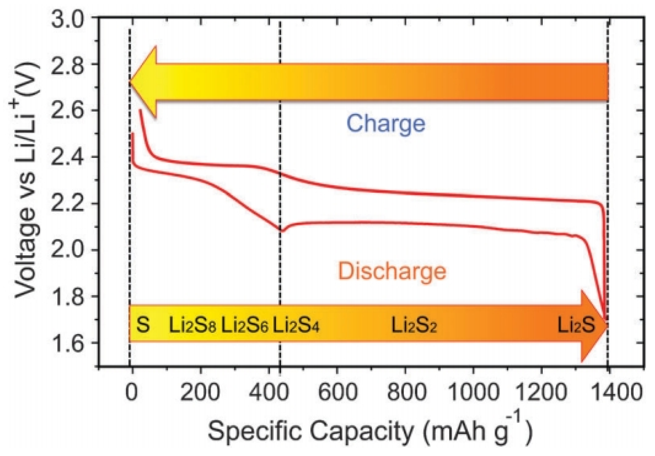
1.1. Working Mechanism of Lithium–Sulphur Batteries

A rechargeable Li–S battery consists of the following primary functional components: a positive electrode (cathode), a negative electrode (anode), electrolyte, and a micro-porous membrane (separator). The operation of rechargeable Li–S batteries is simply based on the theory of Li ions migrating between the cathode and the anode through the electrolyte. In order to achieve high cycling efficiency and long life, the movement of Li ions in anode and cathode hosts should not change or damage the host crystal structure. Figure 2 shows a typical Li–S cell, in which the cathode consists of sulphur (yellow) and a conductive additive (black; for example, carbon black), and a metallic lithium anode which is separated by an organic electrolyte [8].
The electrochemical reactions that occur at the cathode and anode are shown in the following equations:
S8 + 2Li+ + 2e → Li2S8
3Li2S8 + 2Li+ + 2e → 4Li2S6
2Li2S6 + 2Li+ + 2e → 3Li2S4
Li2S4 + 2Li+ + 2e → 2Li2S2
Li2S2 + 2Li+ + 2e → 2Li2S
The first three steps correspond to the high plateau (2.3–2.4 V) in the voltage profile (Figure 3), and the polysulphide species produced in these steps are soluble in the electrolyte [5]. In the last two steps, insoluble Li2S2 and Li2S are formed and precipitate out at the cathode. The corresponding voltage is lower, as indicated by the long plateau at around 2.1 V. The first four steps have fast or moderate kinetics, while the last step of converting Li2S2 to Li2S is difficult, and is impeded by slow solid-state diffusion. Consequently, the voltage drops rapidly once Li2S covers the whole electrode framework, resulting in the termination of discharge.

1.2. The Challenges of Lithium–Sulphur Batteries for Commercialization

1.2.1. Poor Electrical Conductivity of Sulphur and Li2S/Li2S2

First of all, the insulating nature of sulphur (5 × 10⁻³⁰ S·cm−1 at 25 °C) causes remarkably low utilization and poor rate capability [9,10,11]. Moreover, the polysulphides that are produced during cycling are further reduced to insulating Li2S2 and/or Li2S, which also significantly decreases the electrode kinetics and cycling capacities.

1.2.2. Dissolution of Polysulphides and the Related Shuttle Effect

Secondly, the polysulphides which are formed upon cycling can easily dissolve in the organic electrolyte, where they possess high mobility. Dissolved polysulphide anions (Sx2−) can diffuse through the separator to the negative electrode, where they undergo chemical reactions with the lithium metal, leading to the loss of sulphur from the positive electrode, corrosion of the lithium metal, and self-discharge, which influences the electrochemical utilization of sulphur (i.e., discharge capacity), rate capability, and cycle life of Li–S cells [6,12]. Meanwhile, such dissolution and diffusivity will result in the so-called shuttle phenomenon. When discharging, the elemental sulphur is reduced to form soluble high-order polysulphides at the sulphur electrode, which creates a concentration gradient inside the cell. Due to the high concentration of high order polysulphides at the cathode, the diffusion of high order polysulphides towards the anode is observed, which enables the high order polysulphides to react with the lithium anode to form low order polysulphides. This in turn creates a high concentration of low order polysulphides located at the anode of the cell, which diffuse back to the cathode in order to be oxidized back to high order polysulphides. This phenomenon—the diffusion back and forth of polysulphides between the two electrodes—is known as the “polysulphide shuttle” [13]. This shuttle phenomenon will result in extremely low Coulombic efficiency and quick/rapid capacity fading [6].

1.2.3. Self-Discharge

The dissolution of the polysulphides brings about another serious problem—the severe self-discharge observed in Li–S batteries. The sulphur-based species could migrate to the anode side and be converted to polysulphides, leading to a decrease in the open-circuit voltage and discharge capacity.

1.2.4. Volume Expansion

Last but not least, the great volume/morphology change of the S electrode during cycling is another critical factor hindering the large scale commercialisation of Li–S batteries. The deterioration of microstructure or architecture of the electrodes associated with the volume expansion/contraction (~76%) and morphology change of the S electrode material during cycling will lead to poor cycling performances of Li–S batteries, as the volume expansion of electroactive material can damage the electrical connectivity of the carbon host at the cathode [6].

1.3. Strategies for Improving the Performances of Lithium–Sulphur Batteries

As mentioned above, there are many kinds of factors that inhibit the commercialization of Li–S batteries. The strategy for improving a single component may not be able to address all of the issues that are interlinked. More comprehensive approaches are required to remedy this complicated situation in order to dramatically improve the cycling stability and rate capability of Li–S cells.
To date, researchers have proposed various strategies, such as embedding the sulphur into porous and hollow carbon [9,14,15,16,17], limiting the polysulphides shuttle through the use of interlayers [7,18,19], fabricating sulphur electrodes with conductive carbon and polymers [20,21,22,23,24], impregnating the carbon hosts with metal oxides (e.g., TiO2, ZnO, MnO2) [25,26,27,28], and metal organic frameworks (MOFs) [29,30,31] to enhance the adsorption for polysulphides species, as well as developing new types of separators, electrolytes, and binders [32,33,34,35,36], etc., in order to tackle the issues of Li–S batteries. Among them, the strategies of restricting the sulphur within conductive carbon frameworks have proven to be promising. The following sections systematically introduce the roles and the effectiveness of carbon-based materials for the cathode of Li–S batteries.

2. Carbonaceous Materials for the Cathode of Lithium–Sulphur Batteries

It is commonly regarded that the conductivity, specific surface area, and pore volumes of the various carbonaceous materials are the critical factors that affect the electrochemical performance of a sulphur cathode. With respect to practical applications, one must also take the costs of reagents during materials synthesis into consideration. Therefore, as outlined in Table 1, a set of generic advantages and disadvantages of the commonly used carbon frameworks can be established.

2.1. Porous Carbon for the Lithium–Sulphur Electrode

A porous carbon–sulphur (C–S) composite is a mixture of porous carbon and sulphur, where sulphur is mainly encapsulated inside the carbon pores. The porous carbon matrix can not only help trap the dissolved polysulphides, but the nanopores can also accommodate the volume expansion which is displayed upon cycling [5]. Additionally, the conductive carbon matrix can improve the electrical conductivity of the electrode, which can improve the reaction kinetics and the active material utilization [5,14]. Depending on which pore sizes are present, porous carbons can be classified into three categories: (1) micropore (D ≤ 2 nm); (2) mesopore (2 nm ≤ D ≤ 50 nm); and (3) macropore (D ≥ 50 nm). Each type of porous carbon possesses unique properties and morphological advantages.
Before investigating the various types of porous carbon employed in Li–S cells, one must consider the way in which sulphur is encapsulated into the porous carbon matrix. The most common methods are melt-diffusion and chemical in situ deposition. The melt diffusion method is to inject the melted sulphur into the pores of carbonaceous materials, offering the advantage of simplicity but the disadvantage of uneven distribution of sulphur throughout the carbonaceous structure. In contrast, the chemical in situ deposition method can distribute the sulphur homogeneously into materials. The resultant electrode can commonly achieve fast reaction kinetics and eliminate severe polarization. However, this is commonly achieved at the cost of much longer time and expensive instrumentation (e.g., deposition for 16 h with electrochemical workstation) [37].

2.1.1. Microporous Carbon–Sulphur Composites

Micropores were shown to help improve the cycle life of Li–S batteries by effectively confining polysulphide diffusion in the organic electrolyte [38]. Following this, researchers have developed many kinds of microporous carbon as the sulphur host for Li–S batteries [38,39,40,41,42,43,44,45,46,47] (as shown in Table 1), among which sucrose as the carbon source is most popular; i.e., a microporous graphitic carbon of high surface 1416 m2·g−1 and high pore volume of 1.11 cm3·g−1 was prepared by using commercial CaCO3 nanoparticles as a template with sucrose as a carbon source, followed by 1200 °C high-temperature calcination [43]. Sulphur/porous graphitic carbon composites with ultra-high sulphur loading of 88.9 wt% (88.9%S/PC) and lower sulphur loading of 60.8 wt% (60.8%S/PC) were both synthesized by a simple melt-diffusion strategy. When their electrochemical performances were investigated, the 88.9%S/PC exhibited a higher overall discharge capacity of 649.4 mA·h·g−1 (according to C–S composite), higher capacity retention of 84.6% and better Coulombic efficiency of 97.4% after 50 cycles at a rate of 0.1C when compared with the 60.8%S/PC sample. Gao’s group [45] synthesized microporous carbon spheres by refluxing sucrose (5 wt% solution) in 6 M sulphuric acid at 120 °C for 10 h and carbonized the black product at 1000 °C for 2 h under flowing Ar gas. The obtained carbon spheres only displayed micropores, measuring about 0.7 nm, with no mesopores being detected. This composite was stable for 500 cycles, which was related to the strong adsorption of polysulphides by the narrow micropores [45]. They also observed lithiation potential hysteresis during the discharge process, which reflects the additional energy required to overcome the adsorption energy of the short chain sulphur trapped in micropores when using the carbonic ester electrolyte [45]. Similar cathode behaviour of sulphur in microporous carbon was reported by Huang’s group [40].
In addition to the dissolution of soluble polysulphides in organic electrolyte, irreversible Li2S formation also caused poor cycling stability [44]. Recently, a new C–S cathode material comprising short-chain sulphur species (predominately S2) confined in microporous carbonaceous could separate the Li+/S2− ion couple, which can preclude Li2S compound formation and prevents the dissolution of soluble sulphur anions [44]. This new charge/discharge process leads to remarkable cycling stability and reversibility—the C–S cathode stably delivered ~600 mA·h·g−1 capacity over 4020 cycles (0.0014% loss cycle−1) at ~100% Coulombic efficiency.
In addition, Lu’s group [37] developed an electrolysis approach that allowed effective and uniform incorporation of sulphur inside the micropores of carbon nanosheets for advanced Li–S batteries, as shown in Figure 4a. The sulphur–carbon hybrid can be prepared with 70 wt% sulphur loading, in which no nonconductive sulphur agglomerations are formed. Because the incorporated sulphur is electrically connected to the carbon matrix in nature [37], the hybrid cathode shows excellent electrochemical performance; i.e., the monolithic carbon-2 (MLC-2) with ~65 wt% sulphur showed a high capacity of 612 mA·h·g−1 retained after 500 cycles, corresponding to a capacity retention of ~60%, as shown in Figure 4b.

2.1.2. Mesoporous Carbon–Sulphur Composites

Mesoporous carbon is also a good candidate for accommodating the active materials. Moreover, it contributes to the achievement of high initial capacities by the better transport of solvated electrolyte and lithium ions [38]. Early work in this area was performed by Wang et al. [48], where activated carbon with a pore size of around 2.5 nm was used as the conductive matrix. A reversible capacity of 400 mA·h·g−1 was achieved. In 2008, Wang et al. [49] again reported mesoporous C–S composites as the cathode materials for Li–S batteries. The C–S composites were tested in a novel ionic liquid electrolyte consisting of 1-ethyl-3-methylimidazolium bis(trifluoromethanesulfonyl)imide and lithium bistrifluoromethanesulfonimidate. The capacity and cyclic stability of the C–S composite using the ionic liquid electrolyte were much better than the sample tested in a conventional organic solvent electrolyte [49].
In 2009, breakthroughs were made regarding mesoporous C–S composite applications in Li–S batteries by Nazar’s group [50]. They reported CMK-3–S composites that displayed all of the benefits of confinement effects at a small length scale. The retaining conductive carbon framework at nanoscale dimensions afforded excellent accessibility of the active material. It not only acted as an electronic conduit to the active mass encapsulated within, but also served as a mini electrochemical reaction chamber. The entrapment ensured that a more complete redox process took place, and resulted in enhanced utilization of the active sulphur material. Figure 5a illustrates a scanning electron microscopy (SEM) image of CMK-3–S composite, and Figure 5b reveals a schematic diagram of the sulphur (yellow) confined in the interconnected pore structure of mesoporous carbon. From then on, a number of works reported the CMK-3 and CMK-3-based carbon composite as the sulphur host for Li–S batteries [51,52,53,54,55,56,57].
To date, in addition to the mesoporous CMK-3, researchers have developed many other kinds of mesoporous carbon by using various carbon sources as the sulphur host for Li–S batteries (also displayed in Table 1) [58,59,60,61,62,63,64,65,66,67,68,69,70,71,72,73,74,75]. For instance, a mesoporous carbon sphere, where cetyltrimethyl ammonium bromide (CTAB) acted as the carbon source and mesoporous silica provided the hard template with uniform channels, was employed as the ordered conductive carbon matrix (OMCs) in the sulphur cathode for the Li–S battery based on an all-solid-state PEO18Li(CF3SO2)2N–10 wt% SiO2 electrolyte [64]. S–OMCs composite showed excellent cycling performance with a reversible discharge capacity of about 800 mA·h·g−1 after 25 cycles. Bimodal mesoporous carbon (BMC) with 2.0 nm and 5.6 nm mesopores was used with the intention of regulating ion conduction in the mesoporous framework for high-rate performance of Li–S batteries [59]. The high discharge capacities and good cycling stability at a very high current rate of 1675 mA·g−1 can be attributed to the unique bimodal porous structure of the carbon, where the small mesopores are responsible for suppressing the diffusion of polysulphide species into the electrolyte, while the large interconnected cylindrical mesopores favour the rapid transport of solvated Li+ on charge/discharge [59].

2.1.3. Hierarchical Porous Carbon–Sulphur Composites

Due to micropores having a stronger restrictive function on active materials (which achieves better cycling stability), and the mesopores being beneficial to the rapid ion transport, a hierarchical porous carbon (HPC) that can combine the advantages of micropores, mesopores, and even macropores in the sulphur host structure are receiving increased attention among researchers [76,77,78].
As early as 2008, a highly HPC was synthesized by thermally treating a mixture of polyacrylonitrile (PAN) and sodium carbonates in order to be employed as the sulphur host [79]. The S/HPC composite with 57 wt% sulphur delivers an initial high specific capacity up to 1155 mA·h·g−1 and a stable capacity of 745 mA·h·g−1 after 84 cycles at the current density of 40 mA·g−1. Later, Liang’s group [80] reported a hierarchically structured sulphur–carbon nanocomposite material as the high surface-area cathode for rechargeable lithium batteries. First, the mesoporous carbon with 7.3 nm pores was synthesized through a soft-template synthesis method, followed by potassium hydroxide activation, resulting in a bimodal porous carbon with added microporosity of less than 2 nm. Apart from the soft-template method to synthesise the HPC, researchers have developed many hard-template synthesis methods; i.e., SiO2 [81,82,83], Mg(OH)2 [84], MOF [37,85], etc. Recently, multi-chambered micro/mesoporous carbon nanocubes (P@CNC) as new polysulphide reservoirs have been synthesized by Wang’s group [86], where they used the mesoporous MnO as a template, which was coated with poly(3,4-ethylenedioxythiophene) (PEDOT), followed by encapsulating sulphur to form P@CNC–S composites, as shown in Figure 6a–c. The composites demonstrated an initial reversible capacity of 1078 mA·h·g−1 at 0.5C rate, with a capacity retention ratio of 93.2% after 1000 cycles, as shown in Figure 6d.
After conducting a comprehensive summary (as displayed in Table 2), it can be concluded that micropores render better improvement in cycling performance via their unique space confinement effect, but the sulphur loading inside the micropores is very limited. Mesopores can not only further boost the sulphur loading on the electrode, but also provide good entrapment of active species (especially for the small mesopores with sizes 2–5 nm) and sufficient ion transport channels for better rate capability. Macropores can function as ion-reservoirs for fast electrolyte ingress and diffusion, but risk polysulphide migration due to the possible open outlets. It is proposed that the construction of hierarchical pore architectures (i.e., the combination of micro-, meso-, and/or macro-pores) is a promising research and development direction of Li–S batteries.

2.1.4. Hollow Carbon–Sulphur Composites

Several advantages of hollow carbon hosts were suggested: (1) maximizing the amount of sulphur sequestered by the capsules; (2) minimizing polysulphide dissolution and shuttling; (3) preserving fast transport of lithium ions; and (4) good conductivity [78]. Because of these attributes, various kinds of the hollow C–S composites have been synthesized [9,87,88,89,90,91,92,93,94,95].
Jayaprakash et al. [9] used petroleum pitch as carbon precursor and porous silica as template to synthesize mesoporous carbon hollow spheres. Sulphur was incorporated into these mesoporous carbon hollow spheres, and the resulting C–S composites possessed an initial specific discharge capacity of 1071 mA·h·g−1 and maintained a reversible capacity of 974 mA·h·g−1 (at a rate of 0.5C) with 91% capacity retention after 100 cycles.
Complex double-shelled hollow carbon spheres were synthesized using hollow SnO2 spheres as a template, as shown in Figure 7a [90]. Glucose was uniformly coated on the interior and exterior surfaces of the template, and then the complex hollow carbon was derived from the template. The double-shelled structure was designed to host higher amounts of sulphur, suppress the outward diffusion of dissolved polysulphides, and buffer the volume change upon cycling. A satisfactory capacity of around 500 mA·h·g−1 was obtained at a current density of 850 mA·g−1.
Peapod-like mesoporous carbon with interconnected pore channels and large pore volume (4.69 cm3·g−1) as shown in Figure 7b was synthesized and used as the matrix to fabricate C–S composite which served as attractive cathodes for Li–S batteries [93]. Systematic investigation of the C–S composites reveals that the carbon matrix can hold a high but suitable sulphur loading of 84 wt%, and such controllable sulphur-filling also effectively allows the volume expansion of active sulphur during Li+ insertion. Moreover, the thin carbon walls (3–4 nm) of carbon matrix are not only able to shorten the pathway of Li+ transfer and conduct electrons to overcome the poor kinetics of sulphur cathode, but are also flexible to warrant structure stability.

2.1.5. Biochar–Sulphur Composites

Being simple, sustainable, scalable, and environmentally friendly, a diverse range of biomasses with hierarchical structures have provided a number of sustainable templates for the synthesis of functional nanostructured carbon materials [14,96], which have been attracting enthusiastic attention for application in Li–S batteries.
As a source for these biomasses, waste animal tissues are widely used. In 2011, pig bone-derived carbon with a unique hierarchical porous structure was prepared by KOH activation [97]. The pig bone-derived HPC–S composites have been tested as a novel cathode for Li–S batteries, and a high initial capacity of 1265 mA·h·g−1 and 643 mA·h·g−1 after 50 cycles was obtained. Later, Cui’s group [96] reported that crab shells can be used as biotemplates to fabricate hollow carbon nanofibers (CNFs) and then be used to encapsulate sulphur due to its unique Bouligand structure consisting of highly mineralized chitin-protein fibers as shown in Figure 8a,b. The cycling performance is shown in Figure 8c. At a C/5 rate, an initial capacity of 1230 mA·h·g−1 was obtained, indicating 73% sulphur utilization during the first discharge process. After 200 cycles, a reversible capacity of around 810 mA·h·g−1 was still retained, corresponding to a capacity retention of 65%. Moreover, silk [98], fish scales [99], eggshells [100], among others were also employed to synthesise the biochar–sulphur composites as novel cathodes in Li–S batteries.
Plant tissue has also proven to be a good source of porous carbon. For example, kapok fiber-derived carbon nanotiles (KFCNTs) were used as the host of sulphur to construct KFCNTs/S cathodes for Li–S batteries [101]. KFCNTs—with scale-like microstructure—are important for retarding the shuttling of soluble polysulphides, rendering S particles electrically conducting, and accommodating volume variation of S during the Li+ insertion/extraction upon cycling. Owing to their unique microstructure, the resulting KFCNTs/S (93.2 wt%), electrodes exhibited a high and stable volumetric capacity of 504 mA·h·cm−3 (calculated from the whole electrode, the corresponding gravimetric capacity is 524 mA·h·g−1), with a superior capacity retention up to 95.4% after 90 cycles at 0.4 A·g−1. In 2014, our group [14] used KOH-activated bamboo biochar as the sulphur host for Li–S batteries. The as-prepared microporous bamboo–sulphur with 50 wt% sulphur content delivered a high initial capacity of 1295 mA·h·g−1 at a low discharge rate of 160 mA·g−1 and high capacity retention of 550 mA·h·g−1 after 150 cycles at a high discharge rate of 800 mA·g−1, with excellent Coulombic efficiency (≥95%). In addition, some other plant tissues (i.e., poplar catkin [102], pomelo peel [11], and lotus leaves [103]) have also been carbonized in order to mix with sulphur to form biomass C–S composites as environmentally friendly, sustainable cathodes in Li–S batteries.
In addition to animal and plant tissue-sourced biochar, low-cost plant extracts, such as cellulose and glucose, are also good candidates for the synthesis of biochar–sulphur composites. Recently, a nitrogen and sulphur dual-doped carbon (NSC) derived from polyrhodanine@cellulose for advanced Li–S batteries has been reported by Nazar and her co-workers [104]. The as-prepared NSC/S-70 electrode exhibited a high discharge capacity of 1280 mA·h·g−1 and 830 mA·h·g−1 at C/5 and 2C rates, respectively. At C/5, the capacity of NSC/S-70 stabilized at 1080 mA·h·g−1 at 100 cycles. Meanwhile, Fellinger’s group [105] reported an ionothermal sol–gel strategy to synthesize hierarchically porous carbon aerogels doped with different heteroatoms by using biomass precursors (glucose, glucosamine, glucose + cellulose triacetate (TCA), or glucosamine + TCA) in a scalable process. Morphologically similar but chemically different materials are used to study the influence of heteroatoms in Li–S batteries.

2.2. One-Dimensional Carbon Nanostructure/Sulphur Electrodes

Residual sulphur particles with sizes in the range of microns usually remain within the electrode framework without being encapsulated in pores. The formation of pores in the electrode and inhomogeneous precipitation of lithium sulphide can result in lower active material utilization as cycling proceeds, while the conductive matrix created by the one-dimensional (1D) carbon structural network provides better electrical connection to the active materials and a better encapsulation effect for sulphur due to their 1D structure.

2.2.1. Carbon Nanofiber–Sulphur Composites

Initially, carbon nanofiber (CNF) was used as an additive in the sulphur electrode in order to improve cycling properties [106,107]. In 2011, Elazari et al. [108] synthesized CNF–S composites by impregnating microporous activated carbon fibers with elemental melted sulphur, and Ji et al. [109] encapsulated sulphur in porous CNFs via electrospinning, carbonization, and solution-based chemical reaction–deposition method. The CNF–S composites prepared by two distinctive methods as cathodes for Li–S batteries were both evaluated, and demonstrated good electrochemical performances. Both of them attributed the good electrochemical performance to the high electrical conductivity and the extremely high surface area of the CNFs that homogeneously disperse and immobilize S on their porous structures, alleviating the polysulphide shuttle phenomenon. Following this line of research, Cui’s group [110] used anodic aluminum oxide (AAO) as the template to synthesize hollow CNFs with a high aspect ratio. Sulphur was then loaded into the hollow CNFs by mixing and heating to 155 °C. The schematic diagram of the high aspect ratio 1D hollow CNF–S composite is shown in Figure 9a. The presence of the AAO membrane prevents the coating of sulphur onto the outer walls of the CNFs, thus reducing the exposure of sulphur to the electrolyte (Figure 9b). Electrochemical testing showed that this sulphur cathode delivered a high initial discharge capacity of around 1400 mA·h·g−1 with around 75% sulphur loading in the electrode and 1 mg·cm−2 of sulphur content. The cycling capacity retention also showed significant improvement, with a reversible capacity of around 730 mA·h·g−1 after 150 cycles of charge–discharge (Figure 9c). Recently, they found that, by introducing amphiphilic polymers to modify the CNF surface that renders strong interactions between the nonpolar carbon and the polar LixS clusters, the capacity fading mechanism can be reduced further [111]. The modified sulphur cathode showed excellent cycling performance with specific capacity close to 1180 mA·h·g−1 at C/5 current rate. Capacity retention of 80% was achieved over 300 cycles at C/2.
A C–S composite based on vapor-grown carbon fiber (VGCF) was synthesized for Li–S batteries by KOH activation and melt-diffusion strategy in 2013 by Deng et al. [112]. It was found that the S-VGCF treated by KOH activation (S-aVGCF) cathode exhibited better electrochemical reversibility, higher active material utilization, and less severe polysulphide shuttle than both a pristine sulphur cathode and an S-raw VGCF composite cathode. More recently, porous CNFs as sulphur hosts for Li–S batteries were prepared by carbonized polymers, such as PAN and polypyrrole [113,114].

2.2.2. Carbon Nanotube–Sulphur Composites

Like CNFs, carbon nanotubes (CNTs) were first used as an inactive additive material for elemental sulphur positive electrodes for Li–S rechargeable batteries [115]. Following this, the multi-walled carbon nanotubes–sulphur (MWCNTs–S) nanocomposite was prepared by heating a mixture of sublimed S and MWCNTs in certain conditions by Zhang et al. [116]. In addition, S-coated-MWCNTs prepared through capillarity action between the S and MWCNTs could maintain a reversible capacity of 670 mA·h·g−1 after 60 cycles, showing a greatly enhanced cyclability when compared with the sulphur cathode prepared by simple MWCNTs addition [117]. However, it proved difficult to homogenously disperse the sulphur through the carbon by simply heating the S and CNTs, resulting in low sulphur utilization and poor cyclicability of the battery. Therefore, a new method of synthesizing a high performance MWCNTs–S composite cathode material for Li–S battery by solvent exchange was realised [118]. The synthesis process was as follows: the acid-treated MWCNTs were dispersed into 200 mL 1% (w/w) sodium dodecyl sulfate (SDS) aqueous solution, while the sublimated sulphur was dissolved into purified tetrahydrofuran (THF) to get a saturated solution. After that, 30 mL saturated solution (nearly 0.16 mol·L−1) was added into the solution containing modified MWCNTs and SDS under continuous strong stirring. After separating the suspension and washing with distilled water three times, the MWCNTs–S composite with 60% sulphur content was collected. From then on, researchers realized that the sulphur precipitating in solution can be dispersed homogeneously within CNTs, which triggered a number of works about the direct-precipitation method to synthesise CNTs–S composites as the cathode material for Li–S batteries [119,120,121,122,123].
Aligned CNTs–S composite cathodes with high sulphur loading (90%) were investigated by Cheng et al. [124]. The ultra-high loading amount of sulphur was attributed to the open, ordered, straight pore structure of aligned CNTa scaffolds for the uniform distribution of fine sulphur particles. The high sulphur-loaded composite yielded a high tap density with 1116.0 mA·h·cm−3.
The coating of an ultrathin sulphur nanolayer on a prepared CNTs film through a simple two-step heating process was developed by Jin et al. [125]. The CNTs–S composite film with an areal density of ~5 mg·cm−2 had a high sulphur content of 65 wt%, which delivered an initial capacity of 1100 mA·h·g−1 and can retain a reversible capacity of 740 mA·h·g−1 after 100 charge/discharge cycles at 0.1C. Recently, Kim’s group [126] developed a strategy to encapsulate monoclinic sulphur into CNTs, wherein platinum was sputtered on the bottom side to seal the pores and function as a current collector (as shown in Figure 10a), followed by a heat treatment at 400 °C. The electrode design, in conjunction with the monoclinic crystal structure, resulted in excellent electrical performance: a specific capacity reaching the theoretical value and substantial capacity retention over 1000 cycles, as shown in Figure 1d. Furthermore, these battery performances were achieved under the highest sulphur content to date: ~81 wt% in the active material.
The energy density of a battery is an important indicator for industrialization. By cutting down or eliminating the amount of binder used during the synthesis of electrodes, energy densities of cells could be significantly enhanced. CNTs—due to their unique 1D structure—can be easily used to fabricate free-standing electrodes loaded with S. In 2012, Hagen et al. [127] proposed a new type of Li–S cathode (vertically-aligned CNTs grown on a nickel foil without any binder), in which the sulphur content could reach as high as 90 wt%. Kaskel et al. [128] reported binder-free vertically aligned (VA) CNTs–S composite electrodes with high sulphur loadings up to 70 wt%, where its discharge capacity could exceed 800 mA·h·g−1 according to the electrode.
In order to further reduce the amount of exposed S in the CNTs–S composites, many approaches—including coating cathodes with a barrier layer [129,130,131], forming three-dimensional (3D) hybrid nanostructures [132,133,134,135,136,137], and producing pores to form hierarchical architectures [138,139,140]—were developed in order to improve the electrochemical performances for Li–S batteries. Table 3 compares the electrochemical performances of various CNTs–S composites.

2.3. Two-Dimensional Carbon Nanostructure/Sulphur Electrodes

Graphene oxide (GO), reduced graphene oxide (RGO), and graphene are classified as two-dimensional carbon due to their ultrathin sheet structure, which contributes to them demonstrating many advantages—i.e., light weight, good flexibility, outstanding mechanical strength, and superior conductivity [4,141]. Therefore, they have been widely applied in electronics, optics, engineering, and are also considered as an excellent host for loading active materials for energy storage and conversion [141]. When used in Li–S batteries, they can not only enhance the conductivity of the cathode, but also accommodate the volume expansion of the sulphur electrode during the charge/discharge process. Thus, there are many works focusing on the fabrication and evaluation of the electrochemical performances of GO/RGO/graphene–sulphur composites as the cathode for Li–S batteries.

2.3.1. Graphene Oxide–Sulphur Composite Cathodes

GO was first applied as a sulphur immobilizer in 2011 [142]. The researchers employed the chemical reaction-deposition strategy to deposit the S on the GO, and the as-prepared GO–S composites showed good cycling stability at low charge/discharge current (0.1 C). In order to better confine the sulphur and accommodate the volume expansion of the sulphur as it is reduced to Li2S, the core–shell structure of sulphur@graphene oxide (S@GO) has been developed. For example, both and Huang and Meng’s group [143,144] prepared core–shell S@GO by the self-assembly of S particles stabilized by a cationic surfactant and anionic GO nanosheets through electrostatic interaction; Zhou’s group [145] reported a strategy of coating GO uniformly on S particles by engineering the ionic strength in various aqueous solutions. Additionally, sulphur (which possesses unique nanostructures), when combined with GO, will contribute to higher electrochemical performances. The GO-wrapped bowl-like sulphur composite (GO–BS, shown in Figure 11a,b) with an internal void space was used as cathode material of Li–S batteries [146], and realized the protection of active material and tolerance of volumetric expansion. The cycling performance of the battery made from GO–BS at 0.2 A·g−1 showed a discharge specific capacity of 507 mA·h·g−1 after 300 cycles, as shown in Figure 11c. The hollow/solid and sub-micron-sized sulphur sphere (Figure 11d,e) were fabricated by adjusting the amount of polyvinylpyrrolidone (PVP) in the reaction system [147]. The hollow S@GO (HS@GO) core–shell composite showed much better cycling performances than that of solid S@GO core–shell composite, as shown in Figure 11f.

2.3.2. Graphene/Reduced Graphene Oxide–Sulphur Composite Cathodes

When GO is reduced, its conductivity increases significantly. Therefore, the RGO–S or graphene–S composites should illustrate better electrochemical performances compared to the relative GO–S cathodes. To date, there have been a large amount of reports wherein RGO–S composites are utilized as the cathodes for Li–S batteries.
As early as 2011, researchers began using the hydrothermal method to reduce GO to RGO, in order to be mixed with sulphur to fabricate RGO–S composites [148]. However, the sulphur content is only 17.6% across whole electrode, which fails to meet the demands of the industry. Later, Dong’s group [149] also used the hydrothermal method to reduce GO, but the team managed to increase the sulphur content to 60.16%. This RGO–S hybrid showed a large reversible capacity of 773 mA·h·g−1 and 662 mA·h·g−1 after 100 cycles at 0.5C and 1C, respectively. It is known that the hydrothermal method is a simple and effective strategy to form the 3D structures; thus, a variety of 3D-RGO–S composites have been synthesised by this hydrothermal reduction method [150,151,152,153], and the as-prepared RGO–S illustrated excellent electrochemical performance. For example, when the RGO sponges underwent melt-diffusion with the sulphur, they retained the 3D structures (as shown in Figure 12a,b) [151]. Due to this unique 3D structure, it showed a reversible and comparable capacity of 4.53 mA·h·cm−2 after 300 cycles (Figure 12c), corresponding to capacity retention of 75.5% (of its highest capacity of 6.0 mA·h·cm−2), resulting in a decay rate as low as 0.08% per cycle for 300 cycles.
Thermal pyrolysis is also widely used for the reduction of GO. Researchers annealed GO at high temperature in inert atmospheres, such as Ar [154,155,156], N2 [157], Ar/H2 [158], as well as in vacuum conditions [159]. As these RGOs are obtained at high temperature, they tend to show excellent conductivity, and could thus accelerate electron transfer, enhance the reaction kinetics, and improve the active materials utilization during the charge/discharge process.
Using chemically reducing agents (e.g., Na2S) to reduce the GO could also yield highly conductive RGO ready for sulphur loading. Nazar’s group [160] prepared a RGO–S composite combining a mixture of GO and the soluble polysulphide Na2S2.4 as both the S source and reductant, while Sun’s group used the Na2SO3 as the sulphur source and the Na2S as the reducing agent [161]. Recently, Du’s group [162] reported a RGO–S composite preparation, again by using Na2SO3 as the sulphur source, but hydrazine as the reducing agent. By using PVP, the sulphur nanospheres (400–500 nm) were first uniformly wrapped by conductive GO sheets through the electrostatic interaction between GO and PVP, followed by the reduction of GO with hydrazine. As a result, the RGO–S composite with 91 wt% sulphur showed a reversible initial capacity of 970 mA·h·g−1 and an average Coulombic efficiency >96% over 100 cycles at a rate of 0.2C. Moreover, there are some other kinds of reducing agents which have been applied during the fabrication of RGO–S composites, such as HI [163,164], H2S [165,166], urea [167], etc. Table 4 compares the performances of various RGO–S composites using different reduction methods or reducing agents.
It is common sense that RGOs derived from the reduction method are multilayered and easily crumpled, whereas single-layered graphene is mechanically stronger and would display superior electrochemical properties when compared to the performances obtained from multilayered graphene composites. With the purpose of obtaining high quality graphene for assembling the high-performance graphene–S cathodes, researchers developed a template-synthesis strategy to obtain the desired few-layered grapheme (FLG). Kumar’s group [168] synthesised a FLG foam by chemical vapor deposition (CVD) via a sacrificial Ni foam template method, followed by drop casting of the sulphur for infiltration into the FLG foam. The obtained free-standing S–FLG foam cathode revealed good electrochemical stability and high rate discharge capacity retention for up to 400 discharge/charge cycles at a high current density of 3200 mA·g−1. Wei’s group [169] used layered double hydroxide nanoflakes as the templates to synthesise double-layer graphene. This unstacked graphene exhibited a 3D topological porous system, which is suitable for accommodating the active materials. The resulting Li–S batteries demonstrated not only excellent cycling stability, but also superior rate capability.
RGO/graphene can be surface-functionalized or doped with heteroatoms for a better immobilization of sulphur by chemical adsorption. In 2014, Lou’s group reported that the amino-functionalized RGO could strongly bind the discharge products (Li2S and Li2S2) to the surface of the cathode [170]. As a result, the RGO enabled the Li–S batteries to display excellent stable capacity retention of 80% for 350 cycles. Recently, Wang’s group reported a synthesis of highly crumpled nitrogen-doped graphene sheets (GS) with ultrahigh pore volume (5.4 cm3·g−1) via a simple thermally induced expansion strategy [171]. Due to the unique pore structure and nitrogen-doping, a strong polysulphide adsorption ability was induced, and Li–S batteries using these wrinkled GS as both the sulphur host and interlayer achieved a high capacity of ~1000 mA·h·g−1 and exceptional cycling stability, even at high sulphur content (≥80 wt%) and sulphur loading (5 mg sulphur/cm2).

2.4. Carbon Interlayers for Lithium–Sulphur Batteries

Discovering novel battery configurations in Li–S systems is another strategy to accommodate the diffusion of polysulphides towards the anode side [172]. The emerging research in the field of interlayers contributes to the significant improvements in the electrochemical performance of Li–S systems.
Manthiram’s group [173] first reported a microporous carbon paper (MCP) inserted between the cathode and separator, as shown in Figure 13a. With the bifunctional MCP between the cathode and separator, a significant improvement not only in the active material utilization, but also in capacity retention was obtained, and the cyclability at 1C rate retained over 1000 mA·h·g−1 after 100 cycles, converting to a retention rate of 85% with an average Coulombic efficiency of 97.6%. Since then, all kinds of porous carbon—such as biomass derived carbon [174,175,176,177], porous carbon fibre [18,178,179,180,181,182,183,184,185,186], CNTs [187,188,189], Ketjen black (KB) in polytetrafluoroethylene (PTFE) latex [190], etc.—have been employed as the interlayer as shown in Table 5 and Figure 13b–d.
Recently, researchers found that a carbon matrix mixed with bits of metal complex could be employed as the interlayer and could further improve the cycling performances of the Li–S batteries when compared to the performances obtained when using a cell with a single carbon matrix interlayer. For example, as early as 2013, Hu’s group [191] demonstrated the effect of atomic layer deposited (ALD) Al2O3 on the reactivation of dissolved polysulphides in Li–S batteries. A 0.5 nm-thick layer of Al2O3 was conformably coated onto highly porous carbon cloth by ALD, and then assembled in a Li–S battery as the interlayer. Compared to half cells without ALD treatment, the ultrathin Al2O3 coating increased the specific discharge capacity by 25% from 907 mA·h·g−1 to 1136 mA·h·g−1 at the first cycle, and by 114% from 358 mA·h·g−1 to 766 mA·h·g−1 at the 40th cycle. Recently, Zhang and his co-workers [192] reported that a multifunctional carbon-nanotube paper/titanium-dioxide barrier effectively reduced active material loss and suppressed the diffusion of lithium polysulphides to the anode. Using this interlayer, an activated carbon/sulphur cathode with 70% sulphur content delivered stable cycling performance and high Coulombic efficiency (~99%) over 250 cycles at a current rate of 0.5C. Huang et al. [193] reported a new freestanding Fe3C/CNF film as an interlayer for high performance Li–S batteries. The battery delivered an excellent specific discharge capacity of 893 mA·h·g−1 after 100 cycles, maintaining 76% of its initial capacity of 1177 mA·h·g−1.
In addition, graphene—due to its unique 2D dimensional structure and high conductivity—is also a good candidate for use as an interlayer for Li–S batteries. As early as 2013, a kind of RGO was applied as the interlayer for Li–S batteries by Wang’s group [194]. The Li–S cell with such a RGO interlayer showed an initial discharge capacity of 1260 mA·h·g−1, with the capacity remaining at 895 mA·h·g−1 after 100 cycles. Later, functionalized graphene and heteroatom-doped graphene membranes were developed as the interlayers for Li–S batteries. For instance, Kung’s group [195] used a kind of free-standing N-doped graphene paper as an interlayer to entrap polysulphides. Density functional theory (DFT) calculations were used to indicate that pyrrolic and pyridinic N atoms interacted more strongly with Li polysulphides than quaternary N atoms. More recently, our group synthesized a porous N and P-dual doped graphene (P-NP-G) and applied it as a blocking layer [7]. After comparative study, the Li–S battery with P-NP-G demonstrated better electrochemical performance than that with the single N- or P-doped graphene. We also used DFT calculations to help understand the mechanisms, and found the P atoms and –P–O groups in the P-NP-G layer offered stronger adsorption to the polysulphides than the N species.

2.5. Carbon-Modified Separators

Carbon materials are widely applied as the conductive scaffolds for Li–S batteries. By the facile modification of a separator with carbon, the polysulphide species diffusing towards the anode side were trapped. In addition, the conductive carbon facilitated the complex reactions by forming an upper current collector on the top surface of cathode materials [172].
Manthiram’s group [196] reported a series of pioneer discoveries in this research field, such as a bifunctional separator with a light-weight Super P carbon-coating that—when used in a Li–S cell—displayed a high initial discharge capacity of 1389 mA·h·g−1 with excellent dynamic stability, and a high reversible capacity of 828 mA·h·g−1 after 200 cycles. A custom separator with an activated CNF (ACNF) filter coated onto a polypropylene membrane was presented [197]. The optimal ACNF20-filter-coated separator demonstrated an overall superior boost in the electrochemical utilization (discharge capacity: 1270 mA·h·g−1) and polysulphide retention (capacity fade rate: 0.13% cycle−1 after 200 cycles). A MWCNTs-modified separator employed as an ultra-light weight bundled polysulphide filter was also developed [198]. The conductive/porous MWCNTs coating acted as an upper current collector, which helped to facilitate electron transport and high active material utilization, as well as acting as a filter to intercept/absorb the migrating polysulphides which suppressed the polysulphide diffusion. As a result, a high discharge capacity of 1324 mA·h·g−1 was achieved, and capacity decay rate of as low as 0.14% was achieved. Moreover, his group also reported single-walled carbon nanotube (SWCNTs)-modulated separators for high performance Li–S batteries [199]. Compared to the simple component of Super P and MWCNTs, a novel separator with a polyethylene glycol (PEG)-supported microporous carbon composite coating was also employed as a polysulphide shelter [200]. The use of MPC substrates aims to physically trap the migrating polysulphide by their micropores. The use of a PEG binder can chemically improve the polysulphide trapping capability and enhance the mechanical strength of the MPC/PEG coating. The MPC/PEG-coated separator allowed the successful implementation of a pure sulphur cathode containing 70 wt% sulphur and led to high discharge capacities, stable cyclability, and good rate performance. After upgrading the Celgard separator to the MPC/PEG-coated separator, the initial discharge capacities (with sulphur utilization) increased from 843 mA·h·g−1 (50%) to 1307 mA·h·g−1 (78%) and from 543 mA·h·g−1 (32%) to 1018 mA·h·g−1 (61%) at C/5 and C/2 rates, respectively.
In 2014, Cheng’s group [201] used one graphene membrane as a current collector (GCC) which was coated with the active pure sulphur, and another graphene membrane coated on the separator (denoted as GCC/S + G-separator as shown in Figure 14a–c). The flexible and conductive graphene layers on both sides of the sulphur electrode provided excellent electric conductivity. The sandwich structure was believed to effectively accommodate the large volumetric expansion of sulphur during lithiation. The battery with a GCC/S + G-separator delivered capacities as high as 1000 mA·h·g−1 and 750 mA·h·g−1 at 1.5 A/g and 6 A/g, respectively, which are roughly 2 and 50 times higher, respectively, than those of the battery with a Al foil/S + separator tested under the same conditions as shown in Figure 14d.
Following Manthiram and Chen’s research groups, various kinds of carbon and carbon-based composites—such as mesoporous carbon [202,203], nitrogen-doped hollow porous carbon spheres [204], KB [205], acetylene black and carbon nano-tube composites [206], GO [207,208], cellular graphene [209], polyvinylidene fluoride-carbon [210], MWCNTs@PEG composite [211], etc.—have been employed to modify the separator in order to improve the cycling performances of Li–S batteries, and the Table 6 illustrates the electrochemical performances of the Li–S batteries by using these various carbon modified separators.

3. Summary and Perspective

Li–S battery technology has experienced a rapid development over the past 20 years. Researchers contribute tremendous efforts on explaining electrochemical mechanisms and refining the structure of the electrode materials and cell configuration for Li–S batteries. A variety of carbonaceous materials are being developed in order to improve electrochemical performances due to the unique physical and chemical properties (e.g., conductivity, morphologies and functional groups) of carbonaceous nanomaterials. In summary, there are mainly two directions in realising these goals.

3.1. Materials Manipulation (Without Sacrificing Sulphur Content)

In order to realise energy densities for Li–S batteries that meet real-world needs, a high sulphur content in the carbon-S composites, a high ratio of carbon-S composites in the electrode, and a high areal coating weight of the carbon–S composites in the electrode are required. Thus, to make Li–S batteries with satisfactory energy density, the electrode materials should be designed according to the following principles: firstly, the carbon host should have large enough pore volume to accommodate a high content of active materials, as well as a reasonable pore size to confine active materials and reduce their dissolution in the electrolytes; thus, porous carbon graphene and CNTs with high Brunauer, Emmett and Teller (BET) surface area, high pore volumes, and reasonable pore size are required. Secondly, improving the conductivity of the carbon host as much as possible ensures high utilization of sulphur, particularly when the electrode displays a high areal coating weight of active materials. Thirdly, electrodes should be fabricated in such a way so as to reduce the binders and conductive additives used, suggesting that binder-free C–S composites are promising. Fourthly, due to polymers and metal oxides (such as polypyrrole [212], PAN [131], polyaniline [213], TiO2 [214], MnO2 [27], MnO [215], ZnO [25], MOFs [31], etc.), it was observed that the binding energy of these materials with sulphur species is stronger than pure carbon materials, but with a much lower conductivity compared with carbon materials. A hybrid nanostructure that combines the advantages of carbon and polymers/metal oxides are good candidates for the sulphur host for high energy density Li–S batteries. Last but not least, sustainable development and costs should also be taken into consideration. Therefore, biochar is an alternative candidate with great potential.

3.2. Novel Cell Configurations

Carbonaceous materials as an interlayer or conductive additive to modify the separator represent a novel practical cell configuration compared to the conventional Li–S cell. These outside-cathode modification methods are simple, yet extraordinarily effective in improving the cell performance because they can effectively trap/block polysulphides, reducing the parasitic reactions, and their ability to reactivate dead sulphur also helps to improve the cyclic stability of Li–S cells [171].
Although there are several challenges that restrict the commercialization of Li–S batteries, the consistent progress via smart engineering of carbon structures for advanced Li–S batteries have brought this technology closer to practical reality. There is no doubt that the Li–S battery is one of the most promising next-generation rechargeable batteries.

Acknowledgments

The authors acknowledge the financial support from the Australian Research Council.

Author Contributions

Xingxing Gu and Luke Hencz contributed to collecting and sorting the data; Xingxing Gu and Shanqing Zhang co-wrote the paper.

Conflicts of Interest

The authors declare no conflict of interest.

References

  1. Wang, J.-G.; Xie, K.; Wei, B. Advanced engineering of nanostructured carbons for lithium-sulphur batteries. Nano Energy 2015, 15, 413–444. [Google Scholar] [CrossRef]
  2. Yang, Z.; Zhang, J.; Kintner-Meyer, M.C.W.; Lu, X.; Choi, D.; Lemmon, J.P.; Liu, J. Electrochemical energy storage for green grid. Chem. Rev. 2011, 111, 3577–3613. [Google Scholar] [CrossRef] [PubMed]
  3. Bruce, P.G.; Freunberger, S.A.; Hardwick, L.J.; Tarascon, J.M. Li-O2 and Li–S batteries with high energy storage. Nat. Mater. 2012, 11, 19–29. [Google Scholar] [CrossRef] [PubMed]
  4. Gu, X.X.; Zhang, S.Q.; Hou, Y.L. Graphene-based sulphur composites for energy storage and conversion in Li–S batteries. Chin. J. Chem. 2016, 34, 11–31. [Google Scholar] [CrossRef]
  5. Yang, Y.; Zheng, G.; Cui, Y. Nanostructured sulphur cathodes. Chem. Soc. Rev. 2013, 42, 3018–3032. [Google Scholar] [CrossRef] [PubMed]
  6. Song, M.K.; Cairns, E.J.; Zhang, Y. Lithium/sulphur batteries with high specific energy: Old challenges and new opportunities. Nanoscale 2013, 5, 2186–2204. [Google Scholar] [CrossRef] [PubMed]
  7. Gu, X.; Tong, C.-J.; Lai, C.; Qiu, J.; Huang, X.; Yang, W.; Wen, B.; Liu, L.-M.; Hou, Y.; Zhang, S. Porous nitrogen and phosphorous dual doped graphene blocking layer for high performance Li–S batteries. J. Mater. Chem. A 2015, 3, 16670–16678. [Google Scholar] [CrossRef]
  8. Scheers, J.; Fantini, S.; Johansson, P. A review of electrolytes for lithium–sulphur batteries. J. Power Sources 2014, 255, 204–218. [Google Scholar] [CrossRef]
  9. Jayaprakash, N.; Shen, J.; Moganty, S.S.; Corona, A.; Archer, L.A. Porous hollow carbon@sulphur composites for high-power lithium-sulphur batteries. Angew. Chem. Int. Ed. 2011, 50, 5904–5908. [Google Scholar] [CrossRef] [PubMed]
  10. Xiao, L.; Cao, Y.; Xiao, J.; Schwenzer, B.; Engelhard, M.H.; Saraf, L.V.; Nie, Z.; Exarhos, G.J.; Liu, J. A soft approach to encapsulate sulphur: polyaniline nanotubes for lithium-sulphur batteries with long cycle life. Adv. Mater. 2012, 24, 1176–1181. [Google Scholar] [CrossRef] [PubMed]
  11. Zhang, J.; Xiang, J.; Dong, Z.; Liu, Y.; Wu, Y.; Xu, C.; Du, G. Biomass derived activated carbon with 3D connected architecture for rechargeable lithium-sulphur batteries. Electrochim. Acta 2014, 116, 146–151. [Google Scholar] [CrossRef]
  12. Lin, Z.; Liang, C. Lithium-sulphur batteries: from liquid to solid cells. J. Mater. Chem. A 2015, 3, 936–958. [Google Scholar] [CrossRef]
  13. Mikhaylik, Y.V.; Akridge, J.R. Polysulphide shuttle study in the Li/S battery system. J. Electrochem. Soc. 2004, 151, A1969–A1976. [Google Scholar] [CrossRef]
  14. Gu, X.; Wang, Y.; Lai, C.; Qiu, J.; Li, S.; Hou, Y.; Martens, W.; Mahmood, N.; Zhang, S. Microporous bamboo biochar for lithium-sulphur batteries. Nano Res. 2015, 8, 129–139. [Google Scholar] [CrossRef]
  15. Rehman, S.; Gu, X.; Khan, K.; Mahmood, N.; Yang, W.; Huang, X.; Guo, S.; Hou, Y. 3D vertically aligned and interconnected porous carbon nanosheets as sulphur immobilizers for high performance lithium-sulphur batteries. Adv. Energy Mater. 2016, 6, 1502518–1502525. [Google Scholar] [CrossRef]
  16. Xin, S.; Yin, Y.-X.; Wan, L.-J.; Guo, Y.-G. Encapsulation of sulphurin a hollow porous carbon substrate for superior Li–S batteries with long lifespan. Part. Part. Syst. Charact. 2013, 30, 321–325. [Google Scholar] [CrossRef]
  17. Li, Z.; Jiang, Y.; Yuan, L.; Yi, Z.; Wu, C.; Liu, Y.; Strasser, P.; Huang, Y. A highly ordered meso@microporous carbon-supported sulphur@smaller sulphur core-shell structured cathode for Li–S batteries. ACS Nano 2014, 8, 9295–9303. [Google Scholar] [CrossRef] [PubMed]
  18. Gu, X.; Lai, C.; Liu, F.; Yang, W.; Hou, Y.; Zhang, S. A conductive interwoven bamboo carbon fiber membrane for Li–S batteries. J. Mater. Chem. A 2015, 3, 9502–9509. [Google Scholar] [CrossRef]
  19. Gu, X.; Tong, C.J.; Rehman, S.; Liu, L.M.; Hou, Y.; Zhang, S. Multifunctional nitrogen-doped loofah sponge carbon blocking layer for high-performance rechargeable lithium batteries. ACS Appl. Mater. Interface 2016, 8, 15991–16001. [Google Scholar] [CrossRef] [PubMed]
  20. Fu, Y.; Manthiram, A. Enhanced cyclability of lithium-sulphur batteries by a polymer acid-doped polypyrrole mixed ionic-electronic conductor. Chem. Mater. 2012, 24, 3081–3087. [Google Scholar] [CrossRef]
  21. Li, G.C.; Hu, J.J.; Li, G.R.; Ye, S.H.; Gao, X.P. Sulphur/activated-conductive carbon black composites as cathode materials for lithium/sulphur battery. J. Power Sources 2013, 240, 598–605. [Google Scholar] [CrossRef]
  22. Su, Y.-S.; Manthiram, A. A facile in situ sulphur deposition route to obtain carbon-wrapped sulphur composite cathodes for lithium–sulphur batteries. Electrochim. Acta 2012, 77, 272–278. [Google Scholar] [CrossRef]
  23. Wang, J.; Yang, J.; Xie, J.; Xu, N. A novel conductive polymer-sulphur composite cathode material for rechargeable lithium-sulphur batteries. Adv. Mater. 2002, 14, 963–965. [Google Scholar] [CrossRef]
  24. Zhou, W.; Yu, Y.; Chen, H.; DiSalvo, F.J.; Abruna, H.D. Yolk-shell structure of polyaniline-coated sulphurfor lithium-sulphur batteries. J. Am. Chem. Soc. 2013, 135, 16736–16743. [Google Scholar] [CrossRef] [PubMed]
  25. Gu, X.; Tong, C.-J.; Wen, B.; Liu, L.-M.; Lai, C.; Zhang, S. Ball-milling synthesis of ZnO@sulphur/carbon nanotubes and Ni(OH)2@sulphur/carbon nanotubes composites for high-performance lithium-sulphur batteries. Electrochim. Acta 2016, 196, 369–376. [Google Scholar] [CrossRef]
  26. Liang, X.; Nazar, L.F. In situ reactive assembly of scalable core–shell sulphur–MnO2 composite cathodes. ACS Nano 2016, 10, 4192–4198. [Google Scholar] [CrossRef] [PubMed]
  27. Sun, W.; Ou, X.; Yue, X.; Yang, Y.; Wang, Z.; Rooney, D.; Sun, K. A simply effective double-coating cathode with MnO2 nanosheets/graphene as functionalized interlayer for high performance lithium-sulphur batteries. Electrochim. Acta 2016, 207, 198–206. [Google Scholar] [CrossRef]
  28. Yu, M.; Ma, J.; Song, H.; Wang, A.; Tian, F.; Wang, Y.; Qiu, H.; Wang, R. Atomic layer deposited TiO2 on a nitrogen-doped graphene/sulphur electrode for high performance lithium-sulphur batteries. Energy Environ. Sci. 2016, 9, 1495–1503. [Google Scholar] [CrossRef]
  29. Demir-Cakan, R.; Morcrette, M.; Nouar, F.; Davoisne, C.; Devic, T.; Gonbeau, D.; Dominko, R.; Serre, C.; Ferey, G.; Tarascon, J.M. Cathode composites for Li–S batteries via the use of oxygenated porous architectures. J. Am. Chem. Soc. 2011, 133, 16154–16160. [Google Scholar] [CrossRef] [PubMed]
  30. Tao, X.; Chen, F.; Xia, Y.; Huang, H.; Gan, Y.; Chen, X.; Zhang, W. Decoration of sulphur with porous metal nanostructures: An alternative strategy for improving the cyclability of sulphur cathode materials for advanced lithium-sulphur batteries. Chem. Commun. 2013, 49, 4513–4515. [Google Scholar] [CrossRef] [PubMed]
  31. Zheng, J.; Tian, J.; Wu, D.; Gu, M.; Xu, W.; Wang, C.; Gao, F.; Engelhard, M.H.; Zhang, J.G.; Liu, J.; et al. Lewis acid-base interactions between polysulphides and metal organic framework in lithium sulphur batteries. Nano Lett. 2014, 14, 2345–2352. [Google Scholar] [CrossRef] [PubMed]
  32. Demir-Cakan, R.; Morcrette, M.; Gueguen, A.; Dedryvere, R.; Tarascon, J.M. Li–S batteries: Simple approaches for superior performance. Energy Environ. Sci. 2013, 6, 176–182. [Google Scholar] [CrossRef]
  33. Li, G.; Ling, M.; Ye, Y.; Li, Z.; Guo, J.; Yao, Y.; Zhu, J.; Lin, Z.; Zhang, S. Acacia senegal-inspired bifunctional binder for longevity of lithium–sulfur batteries. Adv. Energy Mater. 2015, 5. [Google Scholar] [CrossRef]
  34. Lin, Z.; Liu, Z.; Fu, W.; Dudney, N.J.; Liang, C. Phosphorous pentasulfide as a novel additive for high-performance lithium-sulphur batteries. Adv. Funct. Mater. 2013, 23, 1064–1069. [Google Scholar] [CrossRef]
  35. Suo, L.; Hu, Y.S.; Li, H.; Armand, M.; Chen, L. A new class of solvent-in-salt electrolyte for high-energy rechargeable metallic lithium batteries. Nat. Commun. 2013, 4, 1481–1489. [Google Scholar] [CrossRef] [PubMed]
  36. Zhang, Z.; Bao, W.; Lu, H.; Jia, M.; Xie, K.; Lai, Y.; Li, J. Water-soluble polyacrylic acid as a binder for sulphur cathode in lithium-sulphur battery. ECS Electrochem. Lett. 2012, 1, A34–A37. [Google Scholar] [CrossRef]
  37. He, B.; Li, W.C.; Yang, C.; Wang, S.Q.; Lu, A.H. Incorporating sulphur inside the pores of carbons for advanced lithium-sulphur batteries: An electrolysis approach. ACS Nano 2016, 10, 1633–1639. [Google Scholar] [CrossRef] [PubMed]
  38. Xi, K.; Cao, S.; Peng, X.; Ducati, C.; Kumar, R.V.; Cheetham, A.K. Carbon with hierarchical pores from carbonized metal-organic frameworks for lithium sulphur batteries. Chem. Commun. 2013, 49, 2192–2194. [Google Scholar] [CrossRef] [PubMed]
  39. Chen, H.; Wei, Y.; Wang, J.; Qiao, W.; Ling, L.; Long, D. Controllable nitrogen doping of high-surface-area microporous carbons synthesized from an organic-inorganic sol-gel approach for Li–S cathodes. ACS Appl. Mater. Interface 2015, 7, 21188–21197. [Google Scholar] [CrossRef] [PubMed]
  40. Li, Z.; Yuan, L.; Yi, Z.; Sun, Y.; Liu, Y.; Jiang, Y.; Shen, Y.; Xin, Y.; Zhang, Z.; Huang, Y. Insight into the electrode mechanism in lithium-sulphur batteries with ordered microporous carbon confined sulphur as the cathode. Adv. Energy Mater. 2014, 4, 1301473–1301480. [Google Scholar] [CrossRef]
  41. Rao, M.; Li, W.; Cairns, E.J. Porous carbon-sulfur composite cathode for lithium/sulfur cells. Electrochem. Commun. 2012, 17, 1–5. [Google Scholar] [CrossRef]
  42. Ryu, H.S.; Park, J.W.; Park, J.; Ahn, J.-P.; Kim, K.-W.; Ahn, J.-H.; Nam, T.-H.; Wang, G.; Ahn, H.-J. High capacity cathode materials for Li–S batteries. J. Mater. Chem. A 2013, 1, 1573–1578. [Google Scholar] [CrossRef]
  43. Xu, G.L.; Xu, Y.F.; Fang, J.C.; Peng, X.X.; Fu, F.; Huang, L.; Li, J.T.; Sun, S.G. Porous graphitic carbon loading ultra high sulphuras high-performance ccathode of rechargeable lithium-sulphur batteries. ACS Appl. Mater. Interface 2013, 5, 10782–10793. [Google Scholar] [CrossRef] [PubMed]
  44. Xu, Y.; Wen, Y.; Zhu, Y.; Gaskell, K.; Cychosz, K.A.; Eichhorn, B.; Xu, K.; Wang, C. Confined sulphur in microporous carbon renders superior cycling stability in Li/S batteries. Adv. Funct. Mater. 2015, 25, 4312–4320. [Google Scholar] [CrossRef]
  45. Zhang, B.; Qin, X.; Li, G.R.; Gao, X.P. Enhancement of long stability of sulphur cathode by encapsulating sulphur into micropores of carbon spheres. Energy Environ. Sci. 2010, 3, 1531–1537. [Google Scholar] [CrossRef]
  46. Zhang, W.; Qiao, D.; Pan, J.; Cao, Y.; Yang, H.; Ai, X. A Li+-conductive microporous carbon–sulphur composite for Li–S batteries. Electrochim. Acta 2013, 87, 497–502. [Google Scholar] [CrossRef]
  47. Zhou, L.; Huang, T.; Yu, A. Three-dimensional flower-shaped activated porous carbon/sulphur composites as cathode materials for lithium-sulphur batteries. ACS Sustain. Chem. Eng. 2014, 2, 2442–2447. [Google Scholar] [CrossRef]
  48. Wang, J.L.; Yang, J.; Xie, J.Y.; Xu, N.X.; Li, Y. Sulphur-carbon nano-composite as cathode for rechargeable lithium battery based on gel electrolyte. Electrochem. Commun. 2002, 4, 499–502. [Google Scholar] [CrossRef]
  49. Wang, J.; Chew, S.Y.; Zhao, Z.W.; Ashraf, S.; Wexler, D.; Chen, J.; Ng, S.H.; Chou, S.L.; Liu, H.K. Sulphur-mesoporous carbon composites in conjunction with a novel ionic liquid electrolyte for lithium rechargeable batteries. Carbon 2008, 46, 229–235. [Google Scholar] [CrossRef]
  50. Ji, X.; Lee, K.T.; Nazar, L.F. A highly ordered nanostructured carbon–sulphur cathode for lithium–sulphur batteries. Nat. Mater. 2009, 8, 500–506. [Google Scholar] [CrossRef] [PubMed]
  51. Fang, X.; Weng, W.; Ren, J.; Peng, H. A cable-shaped lithium sulphur battery. Adv. Mater. 2016, 28, 491–496. [Google Scholar] [CrossRef] [PubMed]
  52. Ji, X.; Evers, S.; Black, R.; Nazar, L.F. Stabilizing lithium-sulphur cathodes using polysulphide reservoirs. Nat. Commun. 2011, 2, 325–331. [Google Scholar] [CrossRef] [PubMed]
  53. Kim, J.H.; Kim, T.; Jeong, Y.C.; Lee, K.; Park, K.T.; Yang, S.J.; Park, C.R. Stabilization of insoluble discharge products by facile aniline modification for high performance Li–S batteries. Adv. Energy Mater. 2015, 5, 1500268–1500277. [Google Scholar] [CrossRef]
  54. Li, Q.; Zhou, C.; Ji, Z.; Han, B.; Feng, L.; Wu, J. High-performance lithium/sulphur batteries by decorating CMK-3/S cathodes with DNA. J. Mater. Chem. A 2015, 3, 7241–7247. [Google Scholar] [CrossRef]
  55. Nagao, M.; Imade, Y.; Narisawa, H.; Kobayashi, T.; Watanabe, R.; Yokoi, T.; Tatsumi, T.; Kanno, R. All-solid-state Li-sulphur batteries with mesoporous electrode and thio-LISICON solid electrolyte. J. Power Sources 2013, 222, 237–242. [Google Scholar] [CrossRef]
  56. Zhao, X.Y.; Tu, J.P.; Lu, Y.; Cai, J.B.; Zhang, Y.J.; Wang, X.L.; Gu, C.D. Graphene-coated mesoporous carbon/sulphur cathode with enhanced cycling stability. Electrochim. Acta 2013, 113, 256–262. [Google Scholar] [CrossRef]
  57. Zhou, X.; Xie, J.; Yang, J.; Zou, Y.; Tang, J.; Wang, S.; Ma, L.; Liao, Q. Improving the performance of lithium-sulphur batteries by graphene coating. J. Power Sources 2013, 243, 993–1000. [Google Scholar] [CrossRef]
  58. Chen, S.-R.; Zhai, Y.-P.; Xu, G.-L.; Jiang, Y.-X.; Zhao, D.-Y.; Li, J.-T.; Huang, L.; Sun, S.-G. Ordered mesoporous carbon/sulphur nanocomposite of high performances as cathode for lithium-sulphur battery. Electrochim. Acta 2011, 56, 9549–9555. [Google Scholar] [CrossRef]
  59. He, G.; Ji, X.; Nazar, L. High “C” rate Li–S cathodes: Sulphur imbibed bimodal porous carbons. Energy Environ. Sci. 2011, 4, 2878–2883. [Google Scholar] [CrossRef]
  60. Hu, W.; Zhang, H.; Wang, M.; Zhang, H.; Qu, C. Tri-modal mesoporous carbon/sulphur nanocomposite for high performance Li–S battery. Electrochim. Acta 2016, 190, 322–328. [Google Scholar] [CrossRef]
  61. Li, J.; Qin, F.; Zhang, L.; Zhang, K.; Li, Q.; Lai, Y.; Zhang, Z.; Fang, J. Mesoporous carbon from biomass: One-pot synthesis and application for Li–S batteries. J. Mater. Chem. A 2014, 2, 13916–13922. [Google Scholar] [CrossRef]
  62. Li, L.-Y.; Chen, Y.-X.; Zhong, B.-H. Synthesis and electrochemical performance of a simple and low-cost sulphur/porous carbon composite cathode for rechargeable lithium sulphur battery. Compos. Part A Appl. Sci. Manuf. 2014, 62, 26–31. [Google Scholar] [CrossRef]
  63. Li, X.; Cao, Y.; Qi, W.; Saraf, L.V.; Xiao, J.; Nie, Z.; Mietek, J.; Zhang, J.-G.; Schwenzer, B.; Liu, J. Optimization of mesoporous carbon structures for lithium–sulphur battery applications. J. Mater. Chem. 2011, 21, 16603–16610. [Google Scholar] [CrossRef]
  64. Liang, X.; Wen, Z.; Liu, Y.; Zhang, H.; Huang, L.; Jin, J. Highly dispersed sulphurin ordered mesoporous carbon sphere as a composite cathode for rechargeable polymer Li/S battery. J. Power Sources 2011, 196, 3655–3658. [Google Scholar] [CrossRef]
  65. Liu, J.; Yang, T.; Wang, D.W.; Lu, G.Q.; Zhao, D.; Qiao, S.Z. A facile soft-template synthesis of mesoporous polymeric and carbonaceous nanospheres. Nat. Commun. 2013, 4, 2798–2804. [Google Scholar] [CrossRef]
  66. Park, M.S.; Jeong, B.O.; Kim, T.J.; Kim, S.; Kim, K.J.; Yu, J.S.; Jung, Y.; Kim, Y.J. Disordered mesoporous carbon as polysulphide reservoir for improved cyclic performance of lithium–sulphur batteries. Carbon 2014, 68, 265–272. [Google Scholar] [CrossRef]
  67. Schuster, J.; He, G.; Mandlmeier, B.; Yim, T.; Lee, K.T.; Bein, T.; Nazar, L.F. Spherical ordered mesoporous carbon nanoparticles with high porosity for lithium-sulphur batteries. Angew. Chem. Int. Ed. 2012, 51, 3591–3595. [Google Scholar] [CrossRef] [PubMed]
  68. See, K.A.; Jun, Y.S.; Gerbec, J.A.; Sprafke, J.K.; Wudl, F.; Stucky, G.D.; Seshadri, R. Sulphur-functionalized mesoporous carbons as sulphur hosts in Li–S batteries: Increasing the affinity of polysulphide intermediates to enhance performance. ACS Appl. Mater. Interface 2014, 6, 10908–10916. [Google Scholar] [CrossRef] [PubMed]
  69. Sohn, H.; Gordin, M.L.; Xu, T.; Chen, S.; Lv, D.; Song, J.; Manivannan, A.; Wang, D. Porous spherical carbon/sulphur nanocomposites by aerosol-assisted synthesis: The effect of pore structure and morphology on their electrochemical performance as lithium/sulphur battery cathodes. ACS Appl. Mater. Interface 2014, 6, 7596–7606. [Google Scholar] [CrossRef] [PubMed]
  70. Song, J.; Xu, T.; Gordin, M.L.; Zhu, P.; Lv, D.; Jiang, Y.-B.; Chen, Y.; Duan, Y.; Wang, D. Nitrogen-doped mesoporous carbon promoted chemical adsorption of sulphur and fabrication of high-areal-capacity sulphur cathode with exceptional cycling stability for lithium-sulphur batteries. Adv. Funct. Mater. 2014, 24, 1243–1250. [Google Scholar] [CrossRef]
  71. Sun, X.G.; Wang, X.; Mayes, R.T.; Dai, S. Lithium–sulphur batteries based on nitrogen-doped carbon and an ionic-liquid electrolyte. ChemSusChem 2012, 5, 2079–2085. [Google Scholar] [CrossRef] [PubMed]
  72. Tao, X.; Chen, X.; Xia, Y.; Huang, H.; Gan, Y.; Wu, R.; Chen, F.; Zhang, W. Highly mesoporous carbon foams synthesized by a facile, cost-effective and template-free Pechini method for advanced lithium–sulphur batteries. J. Mater. Chem. A 2013, 1, 3295–3301. [Google Scholar] [CrossRef]
  73. Wei, Y.; Tao, Y.; Zhang, C.; Wang, J.; Qiao, W.; Ling, L.; Long, D. Layered carbide-derived carbon with hierarchically porous structure for high rate lithium-sulphur batteries. Electrochim. Acta 2016, 188, 385–392. [Google Scholar] [CrossRef]
  74. Weng, W.; Pol, V.G.; Amine, K. Ultrasound assisted design of sulphur/carbon cathodes with partially fluorinated ether electrolytes for highly efficient Li/S batteries. Adv. Mater. 2013, 25, 1608–1615. [Google Scholar] [CrossRef] [PubMed]
  75. Xu, M.; Jia, M.; Mao, C.; Liu, S.; Bao, S.; Jiang, J.; Liu, Y.; Lu, Z. Aspergillus flavus conidia-derived carbon/sulfur composite as a cathode material for high performance lithium–sulfur battery. Sci. Rep. 2016, 6, 18739–18747. [Google Scholar] [CrossRef] [PubMed]
  76. Choudhury, S.; Agrawal, M.; Formanek, P.; Jehnichen, D.; Fischer, D.; Krause, B.; Albrecht, V.; Stamm, M.; Ionov, L. Nanoporous cathodes for high-energy Li–S batteries from gyroid block copolymer templates. ACS Nano 2015, 9, 6147–6157. [Google Scholar] [CrossRef] [PubMed]
  77. Ding, B.; Yuan, C.; Shen, L.; Xu, G.; Nie, P.; Zhang, X. Encapsulating sulphur into hierarchically ordered porous carbon as a high-performance cathode for lithium-sulphur batteries. Chem. Eur. J. 2013, 19, 1013–1019. [Google Scholar] [CrossRef] [PubMed]
  78. Wang, D.-W.; Zeng, Q.; Zhou, G.; Yin, L.; Li, F.; Cheng, H.-M.; Gentle, I.R.; Lu, G.Q.M. Carbon–sulphur composites for Li–S batteries: Status and prospects. J. Mater. Chem. A 2013, 1, 9382–9394. [Google Scholar] [CrossRef]
  79. Lai, C.; Gao, X.P.; Zhang, B.; Yan, T.Y.; Zhou, Z. Synthesis and electrochemical performance of sulphur/highly porous carbon composites. J. Phys. Chem. C 2009, 113, 4712–4716. [Google Scholar] [CrossRef]
  80. Liang, C.; Dudney, N.J.; Howe, J.Y. Hierarchically structured sulphur/carbon nanocomposite material for high-energy lithium battery. Chem. Mater. 2009, 21, 4724–4730. [Google Scholar] [CrossRef]
  81. Qu, Y.; Zhang, Z.; Zhang, X.; Ren, G.; Wang, X.; Lai, Y.; Liu, Y.; Li, J. Synthesis of hierarchical porous honeycomb carbon for lithium-sulphur battery cathode with high rate capability and long cycling stability. Electrochim. Acta 2014, 137, 439–446. [Google Scholar] [CrossRef]
  82. Yu, L.; Brun, N.; Sakaushi, K.; Eckert, J.; Titirici, M.M. Hydrothermal nanocasting: Synthesis of hierarchically porous carbon monoliths and their application in lithium–sulphur batteries. Carbon 2013, 61, 245–253. [Google Scholar] [CrossRef]
  83. Zhao, C.; Liu, L.; Zhao, H.; Krall, A.; Wen, Z.; Chen, J.; Hurley, P.; Jiang, J.; Li, Y. Sulphur-infiltrated porous carbon microspheres with controllable multi-modal pore size distribution for high energy lithium–sulphur batteries. Nanoscale 2014, 6, 882–888. [Google Scholar] [CrossRef] [PubMed]
  84. Xu, G.; Ding, B.; Nie, P.; Shen, L.; Dou, H.; Zhang, X. Hierarchically porous carbon encapsulating sulphur as a superior cathode material for high performance lithium–sulphur batteries. ACS Appl. Mater. Interface 2014, 6, 194–199. [Google Scholar] [CrossRef] [PubMed]
  85. Wang, X.; Fang, X.; Guo, X.; Wang, Z.; Chen, L. Sulphur in hierarchically pore-structured carbon pillars as cathode material for lithium–sulphur batteries. Electrochim. Acta 2013, 97, 238–243. [Google Scholar] [CrossRef]
  86. Chen, S.; Sun, B.; Xie, X.; Mondal, A.K.; Huang, X.; Wang, G. Multi-chambered micro/mesoporous carbon nanocubes as new polysulphides reserviors for lithium–sulphur batteries with long cycle life. Nano Energy 2015, 16, 268–280. [Google Scholar] [CrossRef]
  87. Brückner, J.; Thieme, S.; Böttger-Hiller, F.; Bauer, I.; Grossmann, H.T.; Strubel, P.; Althues, H.; Spange, S.; Kaskel, S. Carbon-based anodes for lithium sulphur full cells with high cycle stability. Adv. Funct. Mater. 2013, 24, 1284–1289. [Google Scholar] [CrossRef]
  88. Brun, N.; Sakaushi, K.; Eckert, J.; Titirici, M.M. Carbohydrate-derived nanoarchitectures: On a synergistic effect toward an improved performance in lithium–sulphur batteries. ACS Sustain. Chem. Eng. 2014, 2, 126–129. [Google Scholar] [CrossRef]
  89. Brun, N.; Sakaushi, K.; Yu, L.; Giebeler, L.; Eckert, J.; Titirici, M.M. Hydrothermal carbon-based nanostructured hollow spheres as electrode materials for high-power lithium–sulphur batteries. Phys. Chem. Chem. Phys. 2013, 15, 6080–6087. [Google Scholar] [CrossRef] [PubMed]
  90. Zhang, C.; Hao, B.; Yuan, C.; Guo, Z.; Lou, X.D. Confining sulphur in double-shelled hollow carbon spheres for lithium–sulphur batteries. Angew. Chem. Int. Ed. 2012, 124, 9730–9733. [Google Scholar] [CrossRef]
  91. He, G.; Evers, S.; Liang, X.; Cuisinier, M.; Garsuch, A.; Nazar, L.F. Tailoring porosity in carbon nanospheres for lithium–sulphur battery cathodes. ACS Nano 2013, 7, 10920–10930. [Google Scholar] [CrossRef] [PubMed]
  92. Hu, W.; Zhang, H.; Zhang, Y.; Wang, M.; Qu, C.; Yi, J. Biomineralization-induced self-assembly of porous hollow carbon nanocapsule monoliths and their application in Li–S batteries. Chem. Commun. 2015, 51, 1085–1088. [Google Scholar] [CrossRef] [PubMed]
  93. Li, D.; Han, F.; Wang, S.; Cheng, F.; Sun, Q.; Li, W.C. High sulphur loading cathodes fabricated using peapodlike, large pore volume mesoporous carbon for lithium–sulphur battery. ACS Appl. Mater. Interface 2013, 5, 2208–2213. [Google Scholar] [CrossRef] [PubMed]
  94. Shin, E.S.; Kim, M.S.; Cho, W.I.; Oh, S.H. Sulphur/graphitic hollow carbon sphere nano-composite as a cathode material for high-power lithium-sulphur battery. Nanoscale Res. Lett. 2013, 8, 343–350. [Google Scholar] [CrossRef] [PubMed]
  95. Zhang, K.; Zhao, Q.; Tao, Z.; Chen, J. Composite of sulphur impregnated in porous hollow carbon spheres as the Cathode of Li–S batteries with high performance. Nano Res. 2012, 6, 38–46. [Google Scholar] [CrossRef]
  96. Yao, H.; Zheng, G.; Li, W.; McDowell, M.T.; Seh, Z.; Liu, N.; Lu, Z.; Cui, Y. Crab shells as sustainable templates from nature for nanostructured battery electrodes. Nano Lett. 2013, 13, 3385–3390. [Google Scholar] [CrossRef] [PubMed]
  97. Wei, S.; Zhang, H.; Huang, Y.; Wang, W.; Xia, Y.; Yu, Z. Pig bone derived hierarchical porous carbon and its enhanced cycling performance of lithium–sulphur batteries. Energy Environ. Sci. 2011, 4, 736–740. [Google Scholar] [CrossRef]
  98. Zhang, J.; Cai, Y.; Zhong, Q.; Lai, D.; Yao, J. Porous nitrogen-doped carbon derived from silk fibroin protein encapsulating sulphur as a superior cathode material for high-performance lithium–sulphur batteries. Nanoscale 2015, 7, 17791–17797. [Google Scholar] [CrossRef] [PubMed]
  99. Zhao, S.; Li, C.; Wang, W.; Zhang, H.; Gao, M.; Xiong, X.; Wang, A.; Yuan, K.; Huang, Y.; Wang, F. A novel porous nanocomposite of sulphur/carbon obtained from fish scales for lithium–sulphur batteries. J. Mater. Chem. A 2013, 1, 3334–3339. [Google Scholar] [CrossRef]
  100. Chung, S.-H.; Manthiram, A. Eggshell membrane-derived polysulphide absorbents for highly stable and reversible lithium–sulphur cells. ACS Sustain. Chem. Eng. 2014, 2, 2248–2252. [Google Scholar] [CrossRef]
  101. Tao, X.Y.; Zhang, J.T.; Xia, Y.; Huang, H.; Du, J.; Xiao, H.; Zhang, W.K.; Gan, Y.P. Bio-inspired fabrication of carbon nanotiles for high performance cathode of Li–S batteries. J. Mater. Chem. A 2014, 2, 2290–2296. [Google Scholar] [CrossRef]
  102. Zhang, Y.; Zhao, Y.; Konarov, A.; Li, Z.; Chen, P. Effect of mesoporous carbon microtube prepared by carbonizing the poplar catkin on sulphur cathode performance in Li/S batteries. J. Alloy. Compd. 2015, 619, 298–302. [Google Scholar] [CrossRef]
  103. Yang, S.T.; Yan, C.; Cao, Z.-X.; Shi, M.-J.; Li, Y.-L.; Yin, Y.-H. Preparation of hierarchical porous carbon/sulphur composite based on lotus-leaves and its property for Li–S batteries. J. Inorg. Mater. 2016, 31, 135–140. [Google Scholar]
  104. Pang, Q.; Tang, J.; Huang, H.; Liang, X.; Hart, C.; Tam, K.C.; Nazar, L.F. A nitrogen and sulphur dual-doped carbon derived from polyrhodanine@cellulose for advanced lithium–sulphur batteries. Adv. Mater. 2015, 27, 6021–6028. [Google Scholar] [CrossRef] [PubMed]
  105. Schipper, F.; Vizintin, A.; Ren, J.; Dominko, R.; Fellinger, T.P. Biomass-derived heteroatom-doped carbon aerogels from a salt melt sol-gel synthesis and their performance in Li–S batteries. ChemSusChem 2015, 8, 3077–3083. [Google Scholar] [CrossRef] [PubMed]
  106. Rao, M.; Song, X.; Cairns, E.J. Nano-carbon/sulphur composite cathode materials with carbon nanofiber as electrical conductor for advanced secondary lithium/sulphur cells. J. Power Sources 2012, 205, 474–478. [Google Scholar] [CrossRef]
  107. Choi, Y.-J.; Kim, K.-W.; Ahn, H.-J.; Ahn, J.-H. Improvement of cycle property of sulphur electrode for lithium/sulphur battery. J. Alloy. Compd. 2008, 449, 313–316. [Google Scholar] [CrossRef]
  108. Elazari, R.; Salitra, G.; Garsuch, A.; Panchenko, A.; Aurbach, D. Sulphur-impregnated activated carbon fiber cloth as a binder-free cathode for rechargeable Li–S batteries. Adv. Mater. 2011, 23, 5641–5644. [Google Scholar] [CrossRef] [PubMed]
  109. Ji, L.; Rao, M.; Aloni, S.; Wang, L.; Cairns, E.J.; Zhang, Y. Porous carbon nanofiber–sulfur composite electrodes for lithium/sulfur cells. Energy Environ. Sci. 2011, 4, 5053–5059. [Google Scholar] [CrossRef]
  110. Zheng, G.; Yang, Y.; Cha, J.J.; Hong, S.S.; Cui, Y. Hollow carbon nanofiber-encapsulated sulphur cathodes for high specific capacity rechargeable lithium batteries. Nano Lett. 2011, 11, 4462–4467. [Google Scholar] [CrossRef] [PubMed]
  111. Zheng, G.; Zhang, Q.; Cha, J.J.; Yang, Y.; Li, W.; Seh, Z.W.; Cui, Y. Amphiphilic surface modification of hollow carbon nanofibers for improved cycle life of lithium sulphur batteries. Nano Lett. 2013, 13, 1265–1270. [Google Scholar] [CrossRef] [PubMed]
  112. Deng, Z.; Zhang, Z.; Lai, Y.; Liu, J.; Liu, Y.; Li, J. A sulphur–carbon composite for lithium/sulphur battery based on activated vapor-grown carbon fiber. Solid State Ion. 2013, 238, 44–49. [Google Scholar] [CrossRef]
  113. Wu, Y.; Gao, M.; Li, X.; Liu, Y.; Pan, H. Preparation of mesohollow and microporous carbon nanofiber and its application in cathode material for lithium–sulphur batteries. J. Alloy. Compd. 2014, 608, 220–228. [Google Scholar] [CrossRef]
  114. Yang, J.; Xie, J.; Zhou, X.; Zou, Y.; Tang, J.; Wang, S.; Chen, F.; Wang, L. Functionalized N-doped porous carbon nanofiber webs for a lithium–sulphur battery with high capacity and rate performance. J. Phys. Chem. C 2014, 118, 1800–1807. [Google Scholar] [CrossRef]
  115. Han, S.-C.; Song, M.-S.; Lee, H.; Kim, H.-S.; Ahn, H.-J.; Lee, J.-Y. Effect of multiwalled carbon nanotubes on electrochemical properties of lithium/sulphur rechargeable batteries. J. Electrochem. Soc. 2003, 150, A889–A893. [Google Scholar] [CrossRef]
  116. Zheng, W.; Liu, Y.W.; Hu, X.G.; Zhang, C.F. Novel nanosized adsorbing sulphur composite cathode materials for the advanced secondary lithium batteries. Electrochim. Acta 2006, 51, 1330–1335. [Google Scholar] [CrossRef]
  117. Yuan, L.; Yuan, H.; Qiu, X.; Chen, L.; Zhu, W. Improvement of cycle property of sulphur-coated multi-walled carbon nanotubes composite cathode for lithium/sulphur batteries. J. Power Sources 2009, 189, 1141–1146. [Google Scholar] [CrossRef]
  118. Chen, J.-J.; Jia, X.; She, Q.-J.; Wang, C.; Zhang, Q.; Zheng, M.-S.; Dong, Q.-F. The preparation of nano-sulphur/MWCNTs and its electrochemical performance. Electrochim. Acta 2010, 55, 8062–8066. [Google Scholar]
  119. Ahn, W.; Kim, K.-B.; Jung, K.-N.; Shin, K.-H.; Jin, C.-S. Synthesis and electrochemical properties of a sulphur-multi walled carbon nanotubes composite as a cathode material for lithium sulphur batteries. J. Power Sources 2012, 202, 394–399. [Google Scholar] [CrossRef]
  120. Geng, X.; Rao, M.; Li, X.; Li, W. Highly dispersed sulphur in multi-walled carbon nanotubes for lithium/sulphur battery. J. Solid State Electrochem. 2012, 17, 987–992. [Google Scholar] [CrossRef]
  121. Guo, J.; Xu, Y.; Wang, C. Sulfur-impregnated disordered carbon nanotubes cathode for lithium–sulfur batteries. Nano Lett. 2011, 11, 4288–4294. [Google Scholar] [CrossRef] [PubMed]
  122. Ma, X.Z.; Jin, B.; Xin, P.M.; Wang, H.H. Multiwalled carbon nanotubes-sulphur composites with enhanced electrochemical performance for lithium/sulphur batteries. Appl. Surf. Sci. 2014, 307, 346–350. [Google Scholar] [CrossRef]
  123. Wang, L.; Zhao, Y.; Thomas, M.L.; Byon, H.R. In situ synthesis of bipyramidal sulphur with 3D carbon nanotube framework for lithium–sulphur batteries. Adv. Funct. Mater. 2014, 24, 2248–2252. [Google Scholar] [CrossRef]
  124. Cheng, X.-B.; Huang, J.-Q.; Zhang, Q.; Peng, H.-J.; Zhao, M.-Q.; Wei, F. Aligned carbon nanotube/sulphur composite cathodes with high sulphur content for lithium–sulphur batteries. Nano Energy 2014, 4, 65–72. [Google Scholar] [CrossRef]
  125. Jin, K.; Zhou, X.; Zhang, L.; Xin, X.; Wang, G.; Liu, Z. Sulfur/carbon nanotube composite film as a flexible cathode for lithium–sulfur batteries. J. Phys. Chem. C 2013, 117, 21112–21119. [Google Scholar] [CrossRef]
  126. Moon, S.; Jung, Y.H.; Jung, W.K.; Jung, D.S.; Choi, J.W.; Kim, D.K. Encapsulated monoclinic sulphur for stable cycling of Li–S rechargeable batteries. Adv. Mater. 2013, 25, 6547–6553. [Google Scholar] [CrossRef] [PubMed]
  127. Hagen, M.; Dörfler, S.; Althues, H.; Tübke, J.; Hoffmann, M.J.; Kaskel, S.; Pinkwart, K. Lithium–sulphur batteries–binder free carbon nanotubes electrode examined with various electrolytes. J. Power Sources 2012, 213, 239–248. [Google Scholar] [CrossRef]
  128. Dorfler, S.; Hagen, M.; Althues, H.; Tubke, J.; Kaskel, S.; Hoffmann, M.J. High capacity vertical aligned carbon nanotube/sulfur composite cathodes for lithium–sulfur batteries. Chem. Commun. 2012, 48, 4097–4099. [Google Scholar] [CrossRef] [PubMed]
  129. Huang, J.-Q.; Zhang, Q.; Zhang, S.-M.; Liu, X.-F.; Zhu, W.; Qian, W.-Z.; Wei, F. Aligned sulfur-coated carbon nanotubes with a polyethylene glycol barrier at one end for use as a high efficiency sulfur cathode. Carbon 2013, 58, 99–106. [Google Scholar] [CrossRef]
  130. Wang, L.; Dong, Z.; Wang, D.; Zhang, F.; Jin, J. Covalent bond glued sulphur nanosheet-based cathode integration for long-cycle-life Li–S batteries. Nano Lett. 2013, 13, 6244–6250. [Google Scholar] [CrossRef] [PubMed]
  131. Yin, L.C.; Wang, J.L.; Yang, J.; Nuli, Y.N. A novel pyrolyzed polyacrylonitrile-sulphur@MWCNT composite cathode material for high-rate rechargeable lithium/sulfur batteries. J. Mater. Chem. 2011, 21, 6807–6810. [Google Scholar] [CrossRef]
  132. Bao, W.; Zhang, Z.; Zhou, C.; Lai, Y.; Li, J. Multi-walled carbon nanotubes @ mesoporous carbon hybrid nanocomposites from carbonized multi-walled carbon nanotubes @ metal–organic framework for lithium sulfur battery. J. Power Sources 2014, 248, 570–576. [Google Scholar] [CrossRef]
  133. Chen, R.; Zhao, T.; Lu, J.; Wu, F.; Li, L.; Chen, J.; Tan, G.; Ye, Y.; Amine, K. Graphene-based three-dimensional hierarchical sandwich-type architecture for high-performance Li/S batteries. Nano Lett. 2013, 13, 4642–4649. [Google Scholar] [CrossRef] [PubMed]
  134. Deng, Z.-F.; Zhang, Z.-A.; Lu, H.; Lai, Y.-Q.; Liu, J.; Li, J.; Liu, Y.-X. Vapor-grown carbon fibers enhanced sulphur-multi walled carbon nanotubes composite cathode for lithium/sulphur batteries. Trans. Nonferrous Met. Soc. 2014, 24, 158–163. [Google Scholar] [CrossRef]
  135. Wei, W.; Wang, J.; Zhou, L.; Yang, J.; Schumann, B.; NuLi, Y. CNT enhanced sulfur composite cathode material for high rate lithium battery. Electrochem. Commun. 2011, 13, 399–402. [Google Scholar] [CrossRef]
  136. Xie, J.; Yang, J.; Zhou, X.; Zou, Y.; Tang, J.; Wang, S.; Chen, F. Preparation of three-dimensional hybrid nanostructure-encapsulated sulphur cathode for high-rate lithium sulphur batteries. J. Power Sources 2014, 253, 55–63. [Google Scholar] [CrossRef]
  137. Xu, T.; Song, J.; Gordin, M.L.; Sohn, H.; Yu, Z.; Chen, S.; Wang, D. Mesoporous carbon–carbon nanotube–sulfur composite microspheres for high-areal-capacity lithium–sulfur battery cathodes. ACS Appl. Mater. Interface 2013, 5, 11355–11362. [Google Scholar] [CrossRef] [PubMed]
  138. Chen, J.J.; Zhang, Q.; Shi, Y.N.; Qin, L.L.; Cao, Y.; Zheng, M.S.; Dong, Q.F. A Hierarchical architecture S/MWCNT nanomicrosphere with large pores for lithium sulphur batteries. Phys. Chem. Chem. Phys. 2012, 14, 5376–5382. [Google Scholar] [CrossRef] [PubMed]
  139. Liu, X.; Zhang, Q.; Huang, J.; Zhang, S.; Peng, H.; Wei, F. Hierarchical nanostructured composite cathode with carbon nanotubes as conductive scaffold for lithium-sulfur batteries. J. Energy Chem. 2013, 22, 341–346. [Google Scholar] [CrossRef]
  140. Xu, G.; Ding, B.; Nie, P.; Shen, L.; Wang, J.; Zhang, X. Porous nitrogen-doped carbon nanotubes derived from tubular polypyrrole for energy-storage applications. Chem. Eur. J. 2013, 19, 12306–12312. [Google Scholar] [CrossRef] [PubMed]
  141. Li, Z.; Huang, Y.; Yuan, L.; Hao, Z.; Huang, Y. Status and prospects in sulfur–carbon composites as cathode materials for rechargeable lithium–sulfur batteries. Carbon 2015, 92, 41–63. [Google Scholar] [CrossRef]
  142. Ji, L.; Rao, M.; Zheng, H.; Zhang, L.; Li, Y.; Duan, W.; Guo, J.; Cairns, E.J.; Zhang, Y. Graphene oxide as a sulphur immobilizer in high performance lithium/sulphur cells. J. Am. Chem. Soc. 2011, 133, 18522–18525. [Google Scholar] [CrossRef] [PubMed]
  143. Wu, H.; Huang, Y.; Zong, M.; Ding, X.; Ding, J.; Sun, X. Electrostatic self-assembly of graphene oxide wrapped sulfur particles for lithium–sulfur batteries. Mater. Res. Bull. 2015, 64, 12–16. [Google Scholar] [CrossRef]
  144. Xiao, M.; Huang, M.; Zeng, S.; Han, D.; Wang, S.; Sun, L.; Meng, Y. Sulfur@graphene oxide core–shell particles as a rechargeable lithium–sulfur battery cathode material with high cycling stability and capacity. RSC Adv. 2013, 3, 4914–4916. [Google Scholar] [CrossRef]
  145. Rong, J.; Ge, M.; Fang, X.; Zhou, C. Solution ionic strength engineering as a generic strategy to coat graphene oxide (GO) on various functional particles and its application in high-performance lithium–sulphur (Li–S) batteries. Nano Lett. 2014, 14, 473–479. [Google Scholar] [CrossRef] [PubMed]
  146. Sun, C.; Shi, L.; Fan, C.; Fu, X.; Ren, Z.; Qian, G.; Wang, Z. Bowl-like sulfur particles wrapped by graphene oxide as cathode material of lithium–sulfur batteries. RSC Adv. 2015, 5, 28832–28835. [Google Scholar] [CrossRef]
  147. Zhang, J.; Yang, N.; Yang, X.; Li, S.; Yao, J.; Cai, Y. Hollow sulphur@graphene oxide core-shell composite for high-performance Li–S batteries. J. Alloy. Compd. 2015, 650, 604–609. [Google Scholar] [CrossRef]
  148. Wang, J.-Z.; Lu, L.; Choucair, M.; Stride, J.A.; Xu, X.; Liu, H.-K. Sulphur-graphene composite for rechargeable lithium batteries. J. Power Sources 2011, 196, 7030–7034. [Google Scholar] [CrossRef]
  149. Wei, Z.K.; Chen, J.J.; Qin, L.L.; Nemage, A.W.; Zheng, M.S.; Dong, Q.F. Two-step hydrothermal method for synthesis of sulphur-graphene hybrid and its application in lithium sulphur batteries. J. Electrochem. Soc. 2012, 159, A1236–A1239. [Google Scholar] [CrossRef]
  150. Li, H.; Yang, X.; Wang, X.; Liu, M.; Ye, F.; Wang, J.; Qiu, Y.; Li, W.; Zhang, Y. Dense integration of graphene and sulphur through the soft approach for compact lithium/sulphur battery cathode. Nano Energy 2015, 12, 468–475. [Google Scholar] [CrossRef]
  151. Lu, S.; Chen, Y.; Wu, X.; Wang, Z.; Li, Y. Three-dimensional sulfur/graphene multifunctional hybrid sponges for lithium-sulfur batteries with large areal mass loading. Sci. Rep. 2014, 4, 4629–4632. [Google Scholar] [CrossRef] [PubMed]
  152. Xu, C.; Wu, Y.; Zhao, X.; Wang, X.; Du, G.; Zhang, J.; Tu, J. Sulfur/three-dimensional graphene composite for high performance lithium–sulfur batteries. J. Power Sources 2015, 275, 22–25. [Google Scholar] [CrossRef]
  153. Zhou, G.M.; Yin, L.C.; Wang, D.W.; Li, L.; Pei, S.F.; Gentle, I.R.; Li, F.; Cheng, H.M. Fibrous hybrid of graphene and sulfur nanocrystals for high-performance lithium–sulfur batteries. ACS Nano 2013, 7, 5367–5375. [Google Scholar] [CrossRef] [PubMed]
  154. Chen, F.-B.; Wang, Y.-N.; Wu, B.-R.; Xiong, Y.-K.; Liao, W.-L.; Wu, F.; Zhe, S. Preparation and electrochemical performance of activation graphene/sulfur complex cathode material for lithium-sulfur batteries. J. Inorg. Mater. 2014, 29, 627–632. [Google Scholar]
  155. Huang, X.; Sun, B.; Li, K.; Chen, S.; Wang, G. Mesoporous graphene paper imobilised sulfur as a flexible electrode for lithium–sulfur batteries. J. Mater. Chem. A 2013, 1, 13484–13489. [Google Scholar] [CrossRef]
  156. Xu, J.; Shui, J.; Wang, J.; Wang, M.; Liu, H.-K.; Dou, S.X.; Jeon, I.-Y.; Seo, J.-M.; Baek, J.-B.; Dai, L. Sulfur–graphene nanostructured cathodes via ball-milling for high-performance lithium–sulfur batteries. ACS Nano 2014, 8, 10920–10930. [Google Scholar] [CrossRef] [PubMed]
  157. Wang, Y.-X.; Chou, S.-L.; Liu, H.-K.; Dou, S.-X. The Electrochemical properties of high-capacity sulphur/reduced graphene oxide with different electrolyte systems. J. Power Sources 2013, 244, 240–245. [Google Scholar] [CrossRef]
  158. Wang, C.; Wang, X.; Wang, Y.; Chen, J.; Zhou, H.; Huang, Y. Macroporous free-standing nano-sulfur/reduced graphene oxide paper as stable cathode for lithium-sulfur battery. Nano Energy 2015, 11, 678–686. [Google Scholar] [CrossRef]
  159. Zheng, S.; Wen, Y.; Zhu, Y.; Han, Z.; Wang, J.; Yang, J.; Wang, C. In situ sulfur reduction and intercalation of graphite oxides for Li–S battery cathodes. Adv. Energy Mater. 2014, 4, 1400482–1400491. [Google Scholar] [CrossRef]
  160. Evers, S.; Nazar, L.F. Graphene-enveloped sulfur in a one pot reaction: A cathode with good coulombic efficiency and high practical sulfur content. Chem. Commun. 2012, 48, 1233–1235. [Google Scholar] [CrossRef] [PubMed]
  161. Sun, H.; Xu, G.-L.; Xu, Y.-F.; Sun, S.-G.; Zhang, X.; Qiu, Y.; Yang, S. A composite material of uniformly dispersed sulfur on reduced graphene oxide: Aqueous one-pot synthesis, characterization and excellent performance as the cathode in rechargeable lithium-sulfur batteries. Nano Res. 2012, 5, 726–738. [Google Scholar] [CrossRef]
  162. Liu, Y.; Guo, J.; Zhang, J.; Su, Q.; Du, G. Graphene-wrapped sulfur nanospheres with ultra-high sulfur loading for high energy density lithium–sulfur batteries. Appl. Surf. Sci. 2015, 324, 399–404. [Google Scholar] [CrossRef]
  163. Wu, H.; Huang, Y.; Zong, M.; Fu, H.; Sun, X. Self-assembled graphene/sulfur composite as high current discharge cathode for lithium-sulfur batteries. Electrochim. Acta 2015, 163, 24–31. [Google Scholar] [CrossRef]
  164. Zhao, H.; Peng, Z.; Wang, W.; Chen, X.; Fang, J.; Xu, J. Reduced graphene oxide with ultrahigh conductivity as carbon coating layer for high performance sulphur@reduced graphene oxide cathode. J. Power Sources 2014, 245, 529–536. [Google Scholar] [CrossRef]
  165. Zhang, C.; Liu, D.H.; Lv, W.; Wang, D.W.; Wei, W.; Zhou, G.M.; Wang, S.; Li, F.; Li, B.H.; Kang, F.; et al. A high-density graphene–sulfur assembly: A promising cathode for compact Li–S batteries. Nanoscale 2015, 7, 5592–5597. [Google Scholar] [CrossRef] [PubMed]
  166. Zhang, C.; Lv, W.; Zhang, W.; Zheng, X.; Wu, M.-B.; Wei, W.; Tao, Y.; Li, Z.; Yang, Q.-H. Reduction of graphene oxide by hydrogen sulfide: A promising strategy for pollutant control and as an electrode for Li–S Batteries. Adv. Energy Mater. 2014, 4, 1301565–1301569. [Google Scholar] [CrossRef]
  167. Xu, H.; Deng, Y.; Shi, Z.; Qian, Y.; Meng, Y.; Chen, G. Graphene-encapsulated sulfur (GES) composites with a core–shell structure as superior cathode materials for lithium–sulfur batteries. J. Mater. Chem. A 2013, 1, 15142–15149. [Google Scholar] [CrossRef]
  168. Xi, K.; Kidambi, P.R.; Chen, R.; Gao, C.; Peng, X.; Ducati, C.; Hofmann, S.; Kumar, R.V. Binder free three-dimensional sulphur/few-layer graphene foam cathode with enhanced high-rate capability for rechargeable lithium sulphur batteries. Nanoscale 2014, 6, 5746–5753. [Google Scholar] [CrossRef] [PubMed]
  169. Zhao, M.-Q.; Zhang, Q.; Huang, J.-Q.; Tian, G.-L.; Nie, J.-Q.; Peng, H.-J.; Wei, F. Unstacked double-layer templated graphene for high-rate lithium–sulphur batteries. Nat. Commun. 2014, 5, 3410–3417. [Google Scholar] [CrossRef] [PubMed]
  170. Wang, Z.; Dong, Y.; Li, H.; Zhao, Z.; Wu, H.B.; Hao, C.; Liu, S.; Qiu, J.; Lou, X.W. Enhancing lithium-sulphur battery performance by strongly binding the discharge products on amino-functionalized reduced graphene oxide. Nat. Commun. 2014, 5, 5002–5009. [Google Scholar] [CrossRef] [PubMed]
  171. Song, J.; Yu, Z.; Gordin, M.L.; Wang, D. Advanced sulfur cathode enabled by highly crumpled nitrogen-doped graphene sheets for high-energy-density lithium–sulfur batteries. Nano Lett. 2016, 16, 864–870. [Google Scholar] [CrossRef] [PubMed]
  172. Huang, J.-Q.; Zhang, Q.; Wei, F. Multi-functional separator/interlayer system for high-stable lithium-sulfur batteries: Progress and prospects. Energy Storage Mater. 2015, 1, 127–145. [Google Scholar] [CrossRef]
  173. Su, Y.S.; Manthiram, A. Lithium–sulphur batteries with a microporous carbon paper as a bifunctional interlayer. Nat. Commun. 2012, 3, 1166–1171. [Google Scholar] [CrossRef] [PubMed]
  174. Chung, S.H.; Manthiram, A. Carbonized eggshell membrane as a natural polysulphide reservoir for highly reversible Li–S batteries. Adv. Mater. 2014, 26, 1360–1365. [Google Scholar] [CrossRef] [PubMed]
  175. Chung, S.H.; Manthiram, A. A natural carbonized leaf as polysulphide diffusion inhibitor for high-performance lithium–sulfur battery cells. ChemSusChem 2014, 7, 1655–1661. [Google Scholar] [CrossRef] [PubMed]
  176. Qin, F.R.; Zhang, K.; Fang, J.; Lai, Y.Q.; Li, Q.; Zhang, Z.A.; Li, J. High performance lithium sulphur batteries with a cassava-derived carbon sheet as a polysulphides inhibitor. New J. Chem. 2014, 38, 4549–4554. [Google Scholar] [CrossRef]
  177. Zhang, L.Y.; Wang, Y.Y.; Peng, B.; Yu, W.T.; Wang, H.Y.; Wang, T.; Deng, B.W.; Chai, L.Y.; Zhang, K.; Wang, J.X. Preparation of a macroscopic, robust carbon-fiber monolith from filamentous fungi and its application in Li–S batteries. Green Chem. 2014, 16, 3926–3934. [Google Scholar] [CrossRef]
  178. Cao, Z.; Ma, C.; Yin, Y.; Zhang, J.; Ding, Y.; Shi, M.; Yang, S. Carbonized non-woven fabric films as adsorbing interlayers to enhance electrochemical performance of lithium–sulphur batteries. New J. Chem. 2015, 39, 9659–9664. [Google Scholar] [CrossRef]
  179. Chung, S.H.; Manthiram, A. A hierarchical carbonized paper with controllable thickness as a modulable interlayer system for high performance Li–S batteries. Chem. Commun. 2014, 50, 4184–4187. [Google Scholar] [CrossRef] [PubMed]
  180. Chung, S.H.; Singhal, R.; Kalra, V.; Manthiram, A. Porous carbon mat as an electrochemical testing platform for investigating the polysulphide retention of various cathode configurations in Li–S cells. J. Phys. Chem. Lett. 2015, 6, 2163–2169. [Google Scholar] [CrossRef] [PubMed]
  181. Huang, Y.; Zheng, M.; Lin, Z.; Zhao, B.; Zhang, S.; Yang, J.; Zhu, C.; Zhang, H.; Sun, D.; Shi, Y. Flexible cathodes and multifunctional interlayers based on carbonized bacterial cellulose for high-performance lithium–sulfur batteries. J. Mater. Chem. A 2015, 3, 10910–10918. [Google Scholar] [CrossRef]
  182. Wang, J.; Yang, Y.; Kang, F. Porous carbon nanofiber paper as an effective interlayer for high-performance lithium-sulfur batteries. Electrochim. Acta 2015, 168, 271–276. [Google Scholar] [CrossRef]
  183. Wu, F.; Li, W.; Guan, L.; Ye, Y.; Qian, J.; Yang, X.; Xu, Y.; Chen, R. A polypyrrole-supported carbon paper acting as a polysulphide trap for lithium–sulfur batteries. RSC Adv. 2015, 5, 94479–94485. [Google Scholar] [CrossRef]
  184. Zhang, K.; Li, Q.; Zhang, L.; Fang, J.; Li, J.; Qin, F.; Zhang, Z.; Lai, Y. From filter paper to carbon paper and toward Li–S battery interlayer. Mater. Lett. 2014, 121, 198–201. [Google Scholar] [CrossRef]
  185. Zhang, Z.; Wang, G.; Lai, Y.; Li, J. A freestanding hollow carbon nanofiber/reduced graphene oxide interlayer for high-performance lithium–sulfur batteries. J. Alloy. Compd. 2016, 663, 501–506. [Google Scholar] [CrossRef]
  186. Zu, C.; Su, Y.S.; Fu, Y.; Manthiram, A. Improved lithium–sulfur cells with a treated carbon paper interlayer. Phys. Chem. Chem. Phys. 2013, 15, 2291–2297. [Google Scholar] [CrossRef] [PubMed]
  187. Fu, Y.; Su, Y.S.; Manthiram, A. Highly reversible lithium/dissolved polysulphide batteries with carbon nanotube electrodes. Angew. Chem. Int. Ed. 2013, 52, 6930–6935. [Google Scholar] [CrossRef] [PubMed]
  188. Hwang, J.-Y.; Kim, H.M.; Lee, S.-K.; Lee, J.-H.; Abouimrane, A.; Khaleel, M.A.; Belharouak, I.; Manthiram, A.; Sun, Y.-K. High-energy, high-rate, lithium–sulphur batteries: Synergetic effect of hollow TiO2-webbed carbon nanotubes and a dual functional carbon-paper interlayer. Adv. Energy Mater. 2016, 6. [Google Scholar] [CrossRef]
  189. Su, Y.S.; Manthiram, A. A new approach to improve cycle performance of rechargeable lithium–sulfur batteries by inserting a free-standing MWCNT interlayer. Chem. Commun. 2012, 48, 8817–8819. [Google Scholar] [CrossRef] [PubMed]
  190. Song, J.X.; Yu, Z.X.; Xu, T.; Chen, S.R.; Sohn, H.; Regula, M.; Wang, D.H. Flexible freestanding sandwich-structured sulfur cathode with superior performance for lithium–sulfur batteries. J. Mater. Chem. A 2014, 2, 8623–8627. [Google Scholar] [CrossRef]
  191. Han, X.; Xu, Y.; Chen, X.; Chen, Y.-C.; Weadock, N.; Wan, J.; Zhu, H.; Liu, Y.; Li, H.; Rubloff, G.; et al. Reactivation of dissolved polysulphides in Li–S batteries based on atomic layer deposition of Al2O3 in nanoporous carbon cloth. Nano Energy 2013, 2, 1197–1206. [Google Scholar] [CrossRef]
  192. Xu, G.; Yuan, J.; Tao, X.; Ding, B.; Dou, H.; Yan, X.; Xiao, Y.; Zhang, X. Absorption mechanism of carbon-nanotube paper-titanium dioxide as a multifunctional barrier material for lithium-sulfur batteries. Nano Res. 2015, 8, 3066–3074. [Google Scholar] [CrossRef]
  193. Huang, J.-Q.; Zhang, B.; Xu, Z.-L.; Abouali, S.; Akbari Garakani, M.; Huang, J.; Kim, J.-K. Novel interlayer made from Fe3C/carbon nanofiber webs for high performance lithium–sulfur batteries. J. Power Sources 2015, 285, 43–50. [Google Scholar] [CrossRef]
  194. Wang, X.; Wang, Z.; Chen, L. Reduced graphene oxide film as a shuttle-inhibiting interlayer in a lithium–sulfur battery. J. Power Sources 2013, 242, 65–69. [Google Scholar] [CrossRef]
  195. Han, K.; Shen, J.; Hao, S.; Ye, H.; Wolverton, C.; Kung, M.C.; Kung, H.H. Free-standing nitrogen-doped graphene paper as electrodes for high-performance lithium/dissolved polysulphide batteries. ChemSusChem 2014, 7, 2545–2553. [Google Scholar] [CrossRef] [PubMed]
  196. Chung, S.H.; Manthiram, A. Bifunctional separator with a light-weight carbon-coating for dynamically and statically stable lithium-sulfur batteries. Adv. Funct. Mater. 2014, 24, 5299–5306. [Google Scholar] [CrossRef]
  197. Chung, S.-H.; Han, P.; Singhal, R.; Kalra, V.; Manthiram, A. Electrochemically stable rechargeable lithium–sulfur batteries with a microporous carbon nanofiber filter for polysulphide. Adv. Energy Mater. 2015, 5, 1500738–1500749. [Google Scholar] [CrossRef]
  198. Chung, S.H.; Manthiram, A. High-performance Li–S batteries with an ultra-lightweight MWCNT-coated separator. J. Phys. Chem. Lett. 2014, 5, 1978–1983. [Google Scholar] [CrossRef] [PubMed]
  199. Chang, C.H.; Chung, S.H.; Manthiram, A. Effective stabilization of a high-loading sulphur cathode and a lithium-metal anode in Li–S batteries utilizing SWCNT-modulated separators. Small 2016, 12, 174–179. [Google Scholar] [CrossRef] [PubMed]
  200. Chung, S.-H.; Manthiram, A. A polyethylene glycol-supported microporous carbon coating as a polysulphide trap for utilizing pure sulfur cathodes in lithium–sulfur batteries. Adv. Mater. 2014, 26, 7352–7357. [Google Scholar] [CrossRef] [PubMed]
  201. Zhou, G.; Pei, S.; Li, L.; Wang, D.W.; Wang, S.; Huang, K.; Yin, L.C.; Li, F.; Cheng, H.M. A graphene–pure-sulfur sandwich structure for ultrafast, long-life lithium–sulfur batteries. Adv. Mater. 2014, 26, 625–631. [Google Scholar] [CrossRef] [PubMed]
  202. Balach, J.; Jaumann, T.; Klose, M.; Oswald, S.; Eckert, J.; Giebeler, L. Functional mesoporous carbon-coated separator for long-life, high-energy lithium–sulfur batteries. Adv. Funct. Mater. 2015, 25, 5285–5291. [Google Scholar] [CrossRef]
  203. Balach, J.; Jaumann, T.; Klose, M.; Oswald, S.; Eckert, J.; Giebeler, L. Improved cycling stability of lithium–sulfur batteries using a polypropylene-supported nitrogen-doped mesoporous carbon hybrid separator as polysulphide adsorbent. J. Power Sources 2016, 303, 317–324. [Google Scholar] [CrossRef]
  204. Zhang, Z.; Wang, G.; Lai, Y.; Li, J.; Zhang, Z.; Chen, W. Nitrogen-doped porous hollow carbon sphere-decorated separators for advanced lithium–sulfur batteries. J. Power Sources 2015, 300, 157–163. [Google Scholar] [CrossRef]
  205. Zhao, D.; Qian, X.; Jin, L.; Yang, X.; Wang, S.; Shen, X.; Yao, S.; Rao, D.; Zhou, Y.; Xi, X. Separator modified by Ketjen black for enhanced electrochemical performance of lithium–sulfur batteries. RSC Adv. 2016, 6, 13680–13685. [Google Scholar] [CrossRef]
  206. Wang, Q.; Wen, Z.; Yang, J.; Jin, J.; Huang, X.; Wu, X.; Han, J. Electronic and ionic co-conductive coating on the separator towards high-performance lithium–sulfur batteries. J. Power Sources 2016, 306, 347–353. [Google Scholar] [CrossRef]
  207. Zhang, Y.; Miao, L.; Ning, J.; Xiao, Z.; Hao, L.; Wang, B.; Zhi, L. A graphene-oxide-based thin coating on the separator: an efficient barrier towards high-stable lithium–sulfur batteries. 2D Mater. 2015, 2, 024013. [Google Scholar] [CrossRef]
  208. Zhuang, T.Z.; Huang, J.Q.; Peng, H.J.; He, L.Y.; Cheng, X.B.; Chen, C.M.; Zhang, Q. Rational integration of polypropylene/graphene oxide/Nafion as ternary-layered separator to retard the shuttle of polysulphides for lithium–sulfur batteries. Small 2016, 12, 381–389. [Google Scholar] [CrossRef] [PubMed]
  209. Peng, H.-J.; Wang, D.-W.; Huang, J.-Q.; Cheng, X.-B.; Yuan, Z.; Wei, F.; Zhang, Q. Janus separator of polypropylene-supported cellular graphene framework for sulfur cathodes with high utilization in lithium–sulfur batteries. Adv. Sci. 2016, 3. [Google Scholar] [CrossRef] [PubMed]
  210. Wei, H.; Ma, J.; Li, B.; Zuo, Y.; Xia, D. Enhanced cycle performance of lithium–sulfur batteries using a separator modified with a PVDF-C layer. ACS Appl. Mater. Interface 2014, 6, 20276–20281. [Google Scholar] [CrossRef] [PubMed]
  211. Wang, G.; Lai, Y.; Zhang, Z.; Li, J.; Zhang, Z. Enhanced rate capability and cycle stability of lithium–sulfur batteries with a bifunctional MCNT@PEG-modified separator. J. Mater. Chem. A 2015, 3, 7139–7144. [Google Scholar] [CrossRef]
  212. Wang, Z.; Zhang, S.; Zhang, L.; Lin, R.; Wu, X.; Fang, H.; Ren, Y. Hollow spherical carbonized polypyrrole/sulphurcomposite cathode materials for lithium/sulphur cells with long cycle life. J. Power Sources 2014, 248, 337–342. [Google Scholar] [CrossRef]
  213. Jin, J.; Wen, Z.; Ma, G.; Lu, Y.; Rui, K. Mesoporous carbon/sulphur composite with polyaniline coating for llithium sulphur batteries. Solid State Ion. 2014, 262, 170–173. [Google Scholar] [CrossRef]
  214. Yang, Z.Z.; Wang, H.Y.; Lu, L.; Wang, C.; Zhong, X.B.; Wang, J.G.; Jiang, Q.C. Hierarchical TiO2 spheres as highly efficient polysulphide host for lithium-sulfur batteries. Sci. Rep. 2016, 6. [Google Scholar] [CrossRef]
  215. An, T.; Deng, D.; Lei, M.; Wu, Q.; Tian, Z.; Zheng, M.-S.; Dong, Q.-F. MnO modified carbon nanotubes as sulphur host with enhanced performance in Li/S batteries. J. Mater. Chem. A 2016, 4, 12858–12864. [Google Scholar] [CrossRef]
Figure 1. Comparison of theoretical specific energy and energy density of the lithium/sulphur (Li/S) cell with those of current lithium-ion batteries (LIBs) [6]. Reproduced with permission from [6]. Copyright 2013, Royal Society of Chemistry.
Batteries 02 00033 g001
Figure 2. Schematic illustration of a typical lithium–sulphur (Li–S) cell [8]. Reproduced with permission from [8]. Copyright 2014, Elsevier. LiTFSI: lithium bis (trifluoromethylsulfonyl)imide; DIOX: dioxane; and DME: dimethoxyethane.
Batteries 02 00033 g002
Figure 3. The voltage profile and chemistry of sulphur cathode in the organic electrolyte [5]. Reproduced with permission from [5]. Copyright 2013, Royal Society of Chemistry.
Batteries 02 00033 g003
Figure 4. (a) Illustration of the electrolysis approach to the preparation of sulphur–carbon hybrids; and (b) long-term cyclability and Coulombic efficiency of monolithic carbon-2 (MLC-2) at 0.5C (1C = 1675 mA·g−1) [39]. Reproduced with permission from [39]. Copyright 2016, American Chemical Society.
Batteries 02 00033 g004
Figure 5. (a) Scanning electron microscopy (SEM) image of CMK-3–S; and (b) a schematic diagram of the sulphur (yellow) confined in the interconnected pore structure of CMK-3 [50]. Reproduced with permission from [50]. Copyright 2009, Nature Publishing Group.
Batteries 02 00033 g005
Figure 6. (a) A schematic illustration for preparing poly(3,4-ethylenedioxythiophene) (PEDOT)-coated multi-chambered micro/mesoporous carbon nanocube–sulphur composites (P@CNC–S); (b) SEM image of micro/mesoporous carbon nanocubes; (c) SEM image of P@CNC–S composites with inset high-resolution transmission electron microscopy (HRTEM) image of the details of P@CNC–S composites; (d) cycling performance of P@CNC–S and CNC–S composites at 0.5C and the corresponding Coulombic efficiencies [86]. Reproduced with permission from [86]. Copyright 2015, Elsevier.
Batteries 02 00033 g006
Figure 7. (a) Transmission electron microscopy (TEM) images of mesoporous carbon hollow spheres [90]. Reproduced with permission from [90], Copyright 2012, Wiley-VCH. (b) Peapod-like mesoporous carbon [93]. Reproduced with permission from [93]. Copyright 2013, American Chemical Society.
Batteries 02 00033 g007
Figure 8. (a) Schematic illustration of the fabrication procedure for hollow CNF arrays encapsulating sulphur or silicon electrode materials based on stone crab shell templates; (b) SEM image of crab shell; and (c) capacity and Coulombic efficiency at C/5 and C/2 vs. cycle number [96]. Reproduced with permission from [96]. Copyright 2013, American Chemical Society. CVD: chemical vapor deposition.
Batteries 02 00033 g008
Figure 9. (a) Schematic diagram of the high aspect ratio one-dimensional (1D) hollow CNF–S composite; (b) SEM image of the cathode after sulphur infusion and anodic aluminum oxide (AAO) etching; and (c) cycling performance of the sulphur cathode at C/5 and C/2. The black curve shows cycling performance of the sulphur cathode without AAO etching [110]. Reproduced with permission from [110]. Copyright 2011, American Chemical Society.
Batteries 02 00033 g009
Figure 10. (a) A schematic of each CNTs–S with the dimensions of the key components denoted; and (b) cycling performance of the CNTs–S electrode with a discharge rate of 5C and a charge rate of 2C for 1000 cycles [126]. Reproduced with permission from [126]. Copyright 2013, WILEY-VCH.
Batteries 02 00033 g010
Figure 11. SEM images of (a) sulphur particles; (b) graphene oxide (GO)-wrapped bowl-like sulphur composite; and (c) Cycling performance at rates of 0.2 A·g−1 [146]; reproduced with permission from [146]. Copyright 2015, Royal Society of Chemistry. Field emission SEM (FESEM) images of (d) GO-coated solid and (e) hollow sulphur particles, the insert at the right-top corners are their magnification; (f) cycle performances and corresponding Coulombic efficiencies of sulphur@graphene oxide (S@GO) and hollow S@GO (HS@GO) electrodes at 0.2C [147]. Reproduced with permission from [147]. Copyright 2015, Elsevier.
Batteries 02 00033 g011
Figure 12. SEM image of the interior microstructures of (a) the GO sponges; and (b) S–GS with 80 wt% sulphur; (c) cyclic performance and Coulombic efficiency of the S–GS cathode for a Li–S battery at a current density of 0.1C for 300 cycles. The inset is the Coulombic efficiency [151]. Reproduced with permission from [151]. Copyright 2015, Nature Publishing Group.
Batteries 02 00033 g012
Figure 13. (a) Scheme of the porous carbon employed as the interlayer in the Li–S battery [173]. Reproduced with permission from [173]. Copyright 2012, Nature Publishing Group. (b) A SEM image of natural carbonized leaf with abundant pores [175]. Reproduced with permission from [175]. Copyright 2014, Wiley-VCH, American Chemical Society. (c) SEM image of porous carbon fiber [180]. Reproduced with permission from [180]. Copyright 2015, American Chemical Society. (d) SEM image of MWCNTs paper [189]. Reproduced with permission from [189]. Copyright 2012, The Royal Society of Chemistry.
Batteries 02 00033 g013
Figure 14. (a) Schematic of electrode configurations of: (I) an Al foil, sulphur cathode, and commercial separator (Al foil/S + separator); (II) a graphene current collector (GCC), sulphur cathode, and commercial separator (GCC/S + separator); (III) an Al foil, sulphur cathode, and G-separator (Al foil/S + G-separator); and (IV) a GCC, sulphur cathode, and G-separator. (b) Schematic of a Li–S battery with electrode configuration I. (c) Schematic of a Li–S battery with electrode configuration IV. The paler yellow color represents the reduced shuttle effect. (d) Rate performance of the Li–S batteries with different configurations at different current densities [201]. Reproduced with permission from [201]. Copyright 2013, Wiley-VCH.
Batteries 02 00033 g014
Table 1. Advantages and disadvantages of various carbonaceous materials in Li–S batteries. CNTs: carbon nanotubes; and BET: Brunauer, Emmett and Teller.
Carbon TypePorous CarbonCarbon NanospheresCNTsGraphene
PriceCheapMediumExpensiveExpensive
ConductivityGoodGoodExcellentExcellent
BET surface areaHighMediumMediumLow
Pore volumeHighMediumLowHigh
Table 2. Electrochemical performances of various porous carbonaceous materials in Li–S batteries. PAN: polyacrylonitrile; MOF: metal organic framework; DNA: deoxyribonucleic acid; and HPC: hierarchical porous carbon.
Porous CarbonPore Size/BET Areas/Pore VolumesSulphur Content (wt%)Reversible Capability (at nth Cycle and C-Rate)Reference
Microporous CarbonBamboo carbon0.6–0.75 nm/791.80 m2·g−1/0.38 cm3·g−150550 mA·h·g−1 (150th, 0.5C)[14]
MLC-20.6 nm/576 m2·g−1/−70612 mA·h·g−1 (500th, 0.5C)[37]
Nitrogen-doped microporous carbons<2 nm/1900 m2·g−1/1.2 cm3·g−1401054 mA·h·g−1 (100th, 0.5C)[39]
Carbon FDU0.46 nm/876 m2·g−1/0.93 cm3·g−140608 mA·h·g−1 (170th, 500 mA·g−1)[40]
PAN derived carbon<2 nm/738 m2·g−1/−53.7740 mA·h·g−1 (100th, 0.05C)[41]
Micro-activated carbon1.87 nm/1696 m2·g−1/0.79 cm3·g−154.27500 mA·h·g−1 (50th, 3200 mA·g−1)[42]
Graphitic carbon<2 nm/791.80 m2·g−1/0.38 cm3·g−188.9448.6 mA·h·g−1 (200th, 0.5 C)[43]
Microporous carbon0.5 nm/−/0.217 cm3·g−131600 mA·h·g−1 (4020th, 400 mA·g−1)[44]
Carbon spheres0.7 nm/843.5 m2·g−1/−42650 mA·h·g−1 (500th, 400 mA·g−1)[45]
Carbon microspheres1.0 nm/915 m2·g−1/0.46 cm3·g−140720 mA·h·g−1 (100th,100 mA·g−1)[46]
Flower-shaped activated porous carbon<2 nm/2539 m2·g−1/1.48 cm3·g−160600 mA·h·g−1 (50th, 1600 mA·g−1)[47]
Mesoporous carbonMeso-active carbon2.5 nm/1080 m2·g−1/−30440 mA·h·g−1 (25th, 0.3 mA·cm−2)[48]
CMK-33.3 nm/1976 m2·g−1/2.1 cm3·g−170∼800 mA·h·g−1 (20th, 168 mA·g−1)[49]
Mesoporous carbon12 nm/1100 m2·g−1/2.3 cm3·g−170∼500 mA·h·g−1 (40th, 0.2C)[51]
CMK-3 with aniline groups2–3 nm/639.6 m2·g−1/0.7 cm3·g−142920 mA·h·g−1 (100th, 0.2C)[52]
CMK-3 with DNA3.6 nm/1117 m2·g−1/1.37 cm3·g−156771 mA·h·g−1 (100th, 0.1C)[53]
Ordered mesoporous carbon5.6/2.3 nm/2102 m2·g−1/2.0 cm3·g−160400 mA·h·g−1 (400th, 0.5C)[57]
Bimodal porous carbons5.6/2.0 nm/2300 m2·g−1/2.0 cm3·g−150550 mA·h·g−1 (100th, 1C)[58]
Tri-modal mesoporous carbon2.5/9/15 nm/2371 m2·g−1/2.85 cm3·g−170700 mA·h·g−1 (300th, 0.5C)[59]
Porous biomass-derived carbon20–30 nm/949.85 m2·g−1/3.14 cm3·g−181.29483 mA·h·g−1 (300th, 1C)[60]
Porous carbon-24 nm/735.2 m2·g−1/1.56 cm3·g−158.12730 mA·h·g−1 (105th, 600 mA·g−1)[61]
Mesoporous carbon22 nm/1175 m2·g−1/4.8 cm3·g−150840 mA·h·g−1 (100th, 0.1 C)[62]
Mesoporous carbon nanospheres3.5 nm/857 m2·g−1/−20400 mA·h·g−1 (50th, 1.8C)[64]
Silica templated mesoporous carbon-20a19.9 nm/974 m2·g−1/1.96 cm3·g−160835 mA·h·g−1 (50th, 0.25C)[65]
Spherical ordered mesoporous carbon6.0/3.1 nm/2445 m2·g−1/2.32 cm3·g−170830 mA·h·g−1 (100th, 0.1C)[67]
Sulphur–functionalized mesoporous carbons5.0 nm/1044 m2·g−1/1.4 cm3·g−1-∼300 mA·h·g−1 (100th, 0.1C)[68]
Porous spherical carbon5.16 nm/2008.12 m2·g−1/3.40 cm3·g−159∼850 mA·h·g−1 (50th, 0.1C)[69]
Nitrogen-doped mesoporous carbon2–20 nm/1474.97 m2·g−1/2.08 cm3·g−170800 mA·h·g−1 (100th, 0.70 mA·cm−2)[70]
Mesoporous carbon foam2–10 nm/1478.55 m2·g−1/2.28 cm3·g−157.22878 mA·h·g−1 (50th, 0.05C)[72]
Layered Ti2AlC–derived carbon3–15 nm/1264 m2·g−1/1.89 cm3·g−150724 mA·h·g−1 (200th, 0.5C)[73]
Mesoporous carbon10 nm/215 m2·g−1/−36836 mA·h·g−1 (100th, 230 mA·g−1)[74]
HPCMOF-5 derived hierarchically porous carbon0–200 nm/1945 m2·g−1/1.92 cm3·g−151662.3 mA·h·g−1 (40th, 400 mA·g−1)[38]
Aspergillus flavus derived carbon1.5–3.5 nm/2459.6 m2·g−1/1.30 cm3·g−156.7800 mA·h·g−1 (120th, 0.5C)[75]
Hierarchically ordered porous carbon9/300 nm/850 m2·g−1/1.4 cm3·g−150473.6 mA·h·g−1 (100th, 1C)[77]
PAN derived HPC0–100 nm/1473.2 m2·g−1/−57745 mA·h·g−1 (84th, 40 mA·g−1)[79]
Hierarchically porous carbon<2 nm, 2–4 nm, 7.3 nm/1566.1 m2·g−1/0.503 cm3·g−1 (micropore volume )51.5∼350 mA·h·g−1 (50th, 2500 mA·g−1)[80]
Hierarchical porous honeycomb carbon0–100 nm/614.4 m2·g−1/1.34 cm3·g−166.3564 mA·h·g−1 (100th, 2C)[81]
Hierarchically porous carbon monoliths0–100 nm/1426 m2·g−1/3.097 cm3·g−175469 mA·h·g−1 (25th, −)[82]
Sulphur–infiltrated porous carbon microspheres0–100 nm/2485 m2·g−1/5.1 cm3·g−160904 mA·h·g−1 (100th, 1C)[83]
Mg(OH)2 templated-hierarchically porous carbon0–100 nm/902.5 m2·g−1/2.60 cm3·g−184562 mA·h·g−1 (100th, 1C)[84]
Hierarchically pore-structured carbon pillars0–25 nm/951 m2·g−1/0.484 cm3·g−158456 mA·h·g−1 (40th, 0.1C)[85]
Multi-chambered micro/mesoporous carbon nanocubes0–90 nm/2425 m2·g−1/3.72 cm3·g−172530 mA·h·g−1 (1000th, 5C)[86]
Table 3. Electrochemical performances of various CNTs composites in Li–S batteries. MWCNTs–S: multi-walled carbon nanotubes–sulphur composite; KB: Ketjen black; VA: vertically aligned; PD: polydopamine; PAA: poly acrylic acid; RGO: reduced graphene oxide; GS: graphene sheets; VGCF: vapor-grown carbon fiber; and PNCNTs: porous nitrogen-doped carbon nanotubes.
Composite NameSulphur Content in the Composite (wt%)Reversible Capability (at nth Cycle and C-Rate)Reference
MWCNTs–S~500 mA·h·g−1 (60th, 2 mA·cm−2)[116]
S–coated-MWCNTs68~650 mA·h·g−1 (60th, 100 mA·g−1)[117]
Nano-S/MWCNTs60810 mA·h·g−1 (30th, 300 mA·g−1)[118]
S–MWCNTs75854 mA·h·g−1 (30th, 100 mA·g−1)[119]
Precipitated S/MWCNTs58.3800 mA·h·g−1 (50th, 0.05C)[120]
S-impregnated disordered CNTs40~750 mA·h·g−1 (100th, 0.25C)[121]
MWCNTs–S75592 mA·h·g−1 (50th, 200 mA·g−1)[122]
S–MWCNTs/KB85420 mA·h·g−1 (100th, 1C)[123]
Aligned CNTs/S90~650 mA·h·cm−3 (90th, 0.1C)[124]
S–CNTs65740 mA·h·g−1 (100th, 0.1C)[125]
CNTs–S~81863 mA·h·g−1 (1000th, 5C)[126]
CNTs–S90600 mA·h·g−1 (19th, 0.02C)[127]
VA-CNTs/S70~800 mA·h·g−1 (40th, 0.08C)[128]
S–coated CNTs40~400 mA·h·g−1 (100th, 0.1C)[129]
PD-coated S–MWCNTs–COOH–PAA83640 mA·h·g−1 (500th, 1000 mA·g−1)[130]
PAN–S@MWCNTs30530 mA·h·g−1 (50th, 1C)[131]
MWCNTs@Meso-C/S58.27540 mA·h·g−1 (50th, 0.5 C)[132]
GS–MWCNTs@S70844 mA·h·g−1 (100th, 0.2 C)[133]
VGCFs–S–MWCNTs716 mA·h·g−1 (40th, 335 mA·g−1)[134]
MWCNTs–S–PAN35.1491.5 mA·h·g−1 (100th, 0.5 C)[135]
RGO@MWCNTs–W/S68.9891.5 mA·h·g−1 (200th, 1 C)[136]
Mesoporous carbon–CNTs–S75740 mA·h·g−1 (50th, 0.84 mA·cm−2)[137]
S/MWCNTs nanomicrosphere57780 mA·h·g−1 (200th, 1000 mA·g−1)[138]
Hierarchical CNTs@S coaxial nanocables50713 mA·h·g−1 (150th, 1C)[139]
S/PNCNTs933 mA·h·g−1 (50th, 1C)[140]
Table 4. Electrochemical performances of various graphene composites in Li–S batteries. 3D: three-dimensional; AG: activated graphene; MGP: mesoporous graphene paper; GnPs: graphene nanoplatelets; CP: carbon paper; GSC: graphene–sulfur composite; SGC: S–RGO composite; HDGS: highly dense RGO/sulfur; HRGO: H2S–RGO; and GES: graphene-encapsulated sulfur.
Composite NameReducing Agent/MethodSulphur Content in Graphene/RGO Composite (wt%)Reversible Capability (at nth Cycle and C-Rate)Reference
RGO–SHydrothermal22~550 mA·h·g−1 (40th, 50 mA·g−1)[148]
S–graphene75.2662 mA·h·g−1 (100th, 1000 mA·g−1)[149]
Dense S–graphene69.6770 mA·h·g−1 (300th, 0.5C)[150]
S–GS804.53 mA·h·cm−2 (300th, 0.1C)[151]
S@3D–graphene73700 mA·h·g−1 (100th, 0.1C)[152]
Graphene–S63541 mA·h·g−1 (100th, 750 mA·g−1)[153]
AG/SAr Thermal Pyrolysis65717.1 mA·h·g−1 (200th, 1000 mA·g−1)[154]
MGP–S55689 mA·h·g−1 (50th, 0.1C)[155]
S–GnPs–CP70~700 mA·h·g−1 (500th, 2C)[156]
S/RGON2 Thermal Pyrolysis60625 mA·h·g−1 (200th, 0.1C)[157]
S–RGOH2/Ar Thermal Pyrolysis63658 mA·h·g−1 (200th, 500 mA·g−1)[158]
RGO/SVacuum Thermal Pyrolysis52~880 mA·h·g−1 (220th, 100 mA·g−1)[159]
GSCNa2S~2.487550 mA·h·g−1 (50th, 0.2C)[160]
SGCNa2S63.6440 mA·h·g−1 (500th, 0.75C)[161]
S–nanosphere@grapheneHydrazine91430 mA·h·g−1 (100th, 0.2C)[162]
RGO/SHI80720 mA·h·g−1 (50th, 0.5 mA·cm−2)[163]
S@RGO85480 mA·h·g−1 (200th, 0.05C)[164]
HDGSH2S32~100 mA·h·cm−2 (300th, 0.8C)[165]
HRGO/S~50~525 mA·h·g−1 (100th, 500 mA·g−1)[166]
GESUrea83.3523.1 mA·h·g−1 (500th, 3C)[167]
Table 5. Electrochemical performance of carbon interlayers in Li–S batteries. MCP: microporous carbon paper; ACNF: activated CNF; and PTFE: polytetrafluoroethylene.
Carbon Interlayer TypeSulphur Loading in the ElectrodeReversible Capability (at nth Cycle and C-Rate)Reference
Nitrogen and phosphorous dual-doped graphene70%638 mA·h·g−1(500th, 1C)[7]
Bamboo carbon fiber70%605.7 mA·h·g−1(300th, 1C)[18]
MCP70%1000 mA·h·g−1(100th, 1C)[173]
Carbonized eggshell membrane3.0–3.2 mg·cm−21000 mA·h·g−1(100th, 0.1C)[174]
Carbonized leaf1.3 mg·cm−2800 mA·h·g−1(150th, 0.5C)[175]
Cassava-derived carbon sheet1.6 mg·cm−2811 mA·h·g−1(100th, 0.5C)[176]
Filamentous fungi-derived carbon60%650 mA·h·g−1(100th, 0.5C)[177]
Carbonized non-woven fabrics films2 mg·cm−2677 mA·h·g−1(100th, 1C)[178]
Hierarchical carbonized paper1.1 mg·cm−2780 mA·h·g−1(200th, 2C)[179]
Porous carbon mat1.45 mg·cm−2527 mA·h·g−1(400th, 1C)[180]
Carbonized bacterial cellulose81%620 mA·h·g−1(300th, 800 mA·g−1)[181]
PI-based ACNFs2.5 ± 0.1 mg·cm−2897 mA·h·g−1(100th, 0.1C)[182]
Polypyrrole-supported carbon70%555 mA·h·g−1(200th, 0.5C)[183]
Filter paper derived carbon70%560 mA·h·g−1(50th, 1C)[184]
CNF/RGO1.40 mg·cm−2533.6 mA·h·g−1(400th, 1C)[185]
Carbon paper60%929 mA·h·g−1(100th, 1C)[186]
MWCNTs1.20 mg·cm−21200 mA·h·g−1(100th, 1C)[187]
TiO2–CNTs1.8 mg·cm−2848 mA·h·g−1(100th, 5C)[188]
MWCNTs70%804 mA·h·g−1(100th, 1C)[189]
KB in PTFE latex4.0 mg·cm−21000 mA·h·g−1(150th, 0.5C)[190]
Al2O3–porous carbon cloth1.2 mg·cm−2766 mA·h·g−1(40th, 40 mA·g−1)[191]
Carbon-nanotube paper–titanium dioxide70%575.8 mA·h·g−1(250th, 0.5C)[192]
Fe3C/CNF web70%893 mA·h·g−1(100th, 200 mA·g−1)[193]
RGO–carbon black80%895 mA·h·g−1(100th, 0.1C)[194]
Nitrogen-doped graphene0.4–0.5 mg·cm−2~400 mA·h·g−1(100th, 2C)[195]
Table 6. Electrochemical performances of carbon modified separators in Li–S batteries. SWCNTs: single-walled carbon nanotubes; and PEG: polyethylene glycol.
Carbon Modified Separator Sulphur Content in the ElectrodeReversible Capability (at nth Cycle and C-Rate)Reference
Super P modified separator1.1–1.3 mg·cm−2701 mA·h·g−1 (200th, 2C)[196]
ACNF modified separator2.1–2.3 mg·cm−2819 mA·h·g−1 (200th, 2C)[197]
MWCNTs modified separator70%621 mA·h·g−1 (300th, 1C)[198]
SWCNTs modulated separator6.3 mg·cm−2500 mA·h·g−1 (100th, 0.2C)[199]
PEG–microporous carbon modified separator70%596 mA·h·g−1 (500th, 0.2C)[200]
Graphene modified separator70%680 mA·h·g−1 (300th, 1500 mA·g−1)[201]
Mesoporous carbon modified separator1.55 mg·cm−2591 mA·h·g−1 (500th, 2C)[202]
Polypropylene–nitrogen-doped mesoporous carbon modified separator3.95 mg·cm−2566 mA·h·g−1 (1200th, 0.5C)[203]
Nitrogen-doped hollow porous carbon spheres modified separator1.6 mg·cm−2542 mA·h·g−1 (500th, 1C)[204]
KB modified separator64%815 mA·h·g−1 (100th, 1C)[205]
Acetylene black–CNTs modified separator1.5–2.0 mg·cm−2830 mA·h·g−1 (150th, 0.5C)[206]
GO modified separator1.2–1.4 mg·cm−2750 mA·h·g−1 (100th, 1C)[207]
Polypropylene/GO/Nafion modified separator60%~750 mA·h·g−1 (200th, 0.5C)[208]
Polypropylene–cellular graphene modified separator1.2 mg·cm−2800 mA·h·g−1 (250th, 0.2C)[209]
Polyvinylidene fluoride–carbon modified separator7 mg·cm−2669 mA·h·g−1 (500th, 0.5C)[210]
MWCNTs@PEG modified separator60%490 mA·h·g−1 (500th, 1C)[211]

