Article

Failure Mechanisms of Nickel/Metal Hydride Batteries with Cobalt-Substituted Superlattice Hydrogen-Absorbing Alloy Anodes at 50 °C

1
BASF/Battery Materials-Ovonic, 2983 Waterview Drive, Rochester Hills, MI 48309, USA
2
Department of Chemical Engineering and Materials Science, Wayne State University, Detroit, MI 48202, USA
3
FDK Corporation, 307-2 Koyagimachi, Takasaki 370-0071, Gunma, Japan
*
Author to whom correspondence should be addressed.
Batteries 2016, 2(3), 20; https://doi.org/10.3390/batteries2030020
Submission received: 8 April 2016 / Revised: 16 June 2016 / Accepted: 20 June 2016 / Published: 24 June 2016
(This article belongs to the Special Issue Nickel Metal Hydride Batteries)

Abstract

:
The incorporation of a small amount of Co in the A2B7 superlattice hydrogen absorbing alloy (HAA) can benefit its electrochemical cycle life performance at both room temperature (RT) and 50 °C. The electrochemical properties of the Co-substituted A2B7 and the failure mechanisms of cells using such alloys cycled at RT have been reported previously. In this paper, the failure mechanisms of the same alloys cycled at 50 °C are reported. Compared to that at RT, the trend of the cycle life at 50 °C versus the Co content in the Co-substituted A2B7 HAAs is similar, but the cycle life is significantly shorter. Failure analysis of the cells at 50 °C was performed using X-ray diffraction (XRD), scanning electron microscopy (SEM), X-ray energy dispersive spectroscopy (EDS), and inductively coupled plasma (ICP) analysis. It was found that the elevated temperature accelerates electrolyte dry-out and the deterioration (both pulverization and oxidation) of the A2B7 negative electrode, which are major causes of cell failure when cycling at 50 °C. Cells from HAA with higher Co-content also showed micro-shortage in the separator from the debris of the corrosion of the negative electrode.

Graphical Abstract

1. Introduction

Depending on their particular high energy density and long cycle life, lithium-ion batteries have become the dominant battery type in the consumer and electric vehicle market. However, high cost, limited temperature range, and safety concerns have caused inconvenience and restricted the application of lithium-ion batteries in many fields, including uninterruptible power supply for home appliances, vending machines, cell phone towers, and other on-grid or off-grid stationary energy storage applications. In comparison, the nickel/metal hydride (Ni/MH) battery is a low cost alternative with high safety, long cycle life, excellent rate capabilities, and exceptional high-temperature capabilities for stationary applications [1,2]. The continuous research and development in Ni/MH batteries has enabled continuous use in both consumer type and hybrid electric vehicles [3].
The Ni/MH type battery is capable of operating at high temperatures, up to 85 °C [4], while maintaining a long cycle life [5]. These exceptional high-temperature capabilities make the Ni/MH batteries ideal candidates in extreme environments. In comparison, the performance of commercial lithium-ion batteries deteriorates dramatically at above 70 °C due to electrolyte decomposition [6]. Furthermore, the breakdown of the solid electrolyte interphase starts at 80 °C [7,8] and may result in a thermal runaway [9], which eventually causes fire and explosion [10]. Most rechargeable batteries, including Ni/MH batteries, are optimized to operate at room temperature (RT), and their performances degrade with the increase of temperature. To further improve the high-temperature performance of Ni/MH batteries, their degradation mechanisms at elevated temperatures must be clarified. There are two concerns for Ni/MH applications at high-temperature (>40 °C): charge acceptance and capacity loss. The former has been addressed with composition modifications for the active material used in the positive electrode [11]. The later can be further classified into losses in the positive and negative electrodes. The capacity loss in the positive electrode at high temperature was reviewed in a recent article [12], while the capacity loss in the negative electrode remains to be thoroughly investigated.
There are basically three types of hydrogen absorbing alloy (HAA) that are used as the negative electrode active materials in commercial Ni/MH batteries: misch-metal based AB5 (mainly CaCu5 structure), Laves phase AB2 (mainly C14 and C15 structures), and A2B7 superlattice (mainly Nd2Ni7 and PrNi3 structures). The capacity deteriorations in AB5 and AB2 HAAs were identified to be due to surface passivation of La(OH)3 [13] and surface corrosion which leaches out soluble ions [14], respectively. However, studies on the failure mechanism of A2B7 superlattice HAAs are limited. In the past, we have examined Nd-based [15], La-based [16], and La, Pr, Nd-based [17,18] superlattice HAAs and found that these materials share the same failure mechanism: a passivated rare earth hydroxide surface. Both the Mg-incorporation and the higher rare earth content contribute to the higher rate of surface passivation of superlattice HAAs compared to that of AB5 HAAs.
It is well accepted that B-site substitution can effectively improve the electrochemical performance of HAAs (AB5, AB2, and A2B7) [19,20,21,22]. Previously, we have reported on the electrochemical properties of two series of Mn- and Co-substituted superlattice HAAs as the active materials in the negative electrodes in the sealed cells [23,24], and analyzed their failure mechanisms in sealed full cells at RT [23,24]. These results have shown that both Mn- and Co- substitutions can improve low-temperature cell performance, but not the high-temperature performance [23,24]. The failure mechanisms of cells with superlattice HAAs at high temperatures have not yet been fully understood and require clarification for further improvement of the cell performance at high temperature. In this work, we focused on sealed full cells made with Co-substituted superlattice HAAs and studied the failure mechanisms of the cells cycled at 50 °C.

2. Experimental Setup

The metal hydride (MH) alloys used in this study include five superlattice A2B7 HAAs (C1–C5) and one La-rich AB5 HAA (AB5) as a reference. The compositions of the five A2B7 HAAs are Mm0.83Mg0.17Ni3.14−xAl0.17Cox (x = 0, 0.1, 0.2, 0.3, and 0.4), with variations corresponding to the Co amount of 0 (C1), 2.3 (C2), 4.7 (C3), 7.0 (C4), and 9.3 (C5) at%. These alloys were made by Japan Metals and Chemicals Co. (JMC, Tokyo, Japan). Herein, Mm is the mixed rare earth metal with a composition of 19.6 wt% lanthanum (La), 40.2 wt% praseodymium (Pr), and 40.2 wt% neodymium (Nd). The designed formula for the five A2B7 HAAs is AB3.31. Details on the composition of the Co-substituted A2B7 HAAs can be found in Table 1 of [24]. The La-rich AB5 HAA has a composition of La10.5Ce4.3Pr0.5Nd1.4Ni60.0Co12.7Mn5.9Al4.7 and was supplied by Eutectix (Troy, MI, USA). The same alloys have been used in our previous study of the Co-substituted superlattice A2B7 HAAs [18,24]. The powders of the six different alloys were dry-compacted onto nickel mesh current collectors as negative electrodes. Pairing such negative electrodes with the positive electrodes made with 94.1 wt% CoOOH-coated Ni0.85Co0.12Zn0.03(OH)2, 4.9 wt% Co, and 1 wt% Y2O3 on nickel foam substrates, C-size Ni/MH cells were assembled for electrochemical testing. The separator used was Scimat 700/79 acrylic acid grafted polypropylene/polyethylene, which was supplied by Freudenberg (Weinheim, Germany) and the electrolyte was a NaOH electrolyte (26.8 wt%) with LiOH (1.5 wt%) as an additive for improved high-temperature performance [25]. The designed negative-to-positive capacity ratio was kept at 2.0 in order to balance the over-charge and over-discharge reservoirs [15]. For convenience, C1–C5 and AB5 are used to represent not only the HAA alloys C1–C5 and AB5, but also the cells with corresponding HAA alloys.
The sealed cells were tested using a Maccor Battery Cycler (Tulsa, OK, USA) in a Blue M Oven (TPS Thermal Power Solutions, White Deer, PA, USA) with a set temperature of 50 °C. After the formation process in which the newly sealed cells were charged/discharged at C/3 for three cycles with cut-off voltages of 1.45 V/1 V, they were tested at 50 °C using a 0.5C charge/discharge rate with a discharge cut-off voltage of 0.9 V. The cut-off of the charging process was triggered when the cells reached 105% state-of-charge, based on the initial discharge capacity. The cycle test ended when the capacity dropped below 70% of the initial discharge capacity.
The cells were disassembled after the cycle test and their failure modes were studied by X-ray diffraction (XRD), scanning electron microscopy (SEM), energy dispersive spectroscopy (EDS), and inductively coupled plasma (ICP). The electrolyte residues in the cycled electrodes were removed in a Soxhlet extractor (Thermo Fisher Scientific, Walthan, MA, USA). XRD analysis in the 2θ range of 10°–80° was performed using Cu Kα radiation (λ = 1.5406 Å) on a Philips X'Pert Pro X-ray diffractometer (Amsterdam, The Netherlands) to study the crystal structure of the positive and negative electrodes after cycling. The powders were scraped from the cycled electrodes and sifted into the well of a glass sample holder for XRD. The working voltage of the X-ray generator is 30 kV and current is 15 mA. Scanning was carried out with the angular step size of 0.02° and counting time of 5 s. SEM was carried out using a JEOL-JSM6320F microscope (Tokyo, Japan), with EDS capabilities, to study the morphology and composition of the negative electrodes after cycling. Another JEOL JSM7100 field-emission SEM with EDS was used to obtain the elemental mapping across the battery cross-section (positive electrode/separator/negative electrode). After Soxhlet extraction and drying in nitrogen, the cycled cells were vacuum-impregnated in epoxy and cured overnight. Later, they were ground with SiC paper (180, 320 and 600 grits) and polished with 6 μm and 1 μm diamond compound. SEM analysis was carried out with a 20 kV beam accelerating voltage, 300 pA current and 15 mm working distance. A Thermo iCAP 7400 ICP system (Thermo Fisher Scientific) was used to determine the composition of the Soxhlet extraction solution. The parameters used in ICP measurement were: RF power—1150 W, exposure time—10 s, nebulizer gas flow—0.55 L·min−1 and three replicates.

3. Results and Discussion
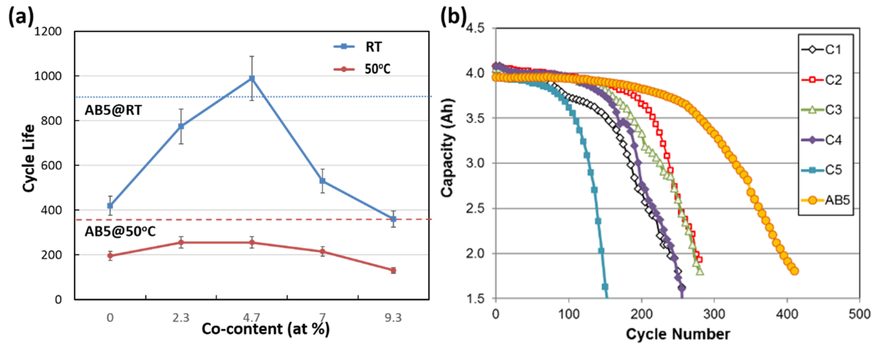
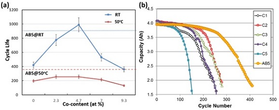
High-temperature charge/discharge tests were performed on the C-size cells at a fixed temperature, 50 °C, with a rate of 0.5C for charge and discharge, until the capacity dropped below 70% of the initial capacity, which is deemed as the end of cycle life. Later, the cells were disassembled and the electrodes and separators were characterized by XRD, SEM/EDS, and ICP to study the failure mechanisms of the cells cycled at 50 °C.

3.1. Cycle Life

The cycle life versus Co content at 50 °C and RT (20 °C) for samples C1–C5 and AB5 are shown in Figure 1a, and the evolution of capacity as a function of cycle number at 50 °C is shown in Figure 1b (adapted from [24]). The blue dotted line and red dashed line indicate the cycle life of AB5 at RT and 50 °C, respectively. For each material, three identical cells were fabricated and tested, and the results show that the error in cycle life measurement is no more than 10% in this study. To show the best performance for each material, the data points in Figure 1 are from the cells with the longest cycle life. At 50 °C, the cycle life for all samples is dramatically lower than those cycled at RT. The maximum cycle life for the 50 °C series is 255 cycles for both C2 and C3, compared to 775 and 990 cycles for C2 and C3, respectively, at RT. Similar to the trend for the RT series, at 50 °C the cycle life increases with incorporation of Co and then decreases with further increases in Co content. The AB5 sample exhibited a longer cycle life at 50 °C than all five superlattice A2B7 HAA samples.

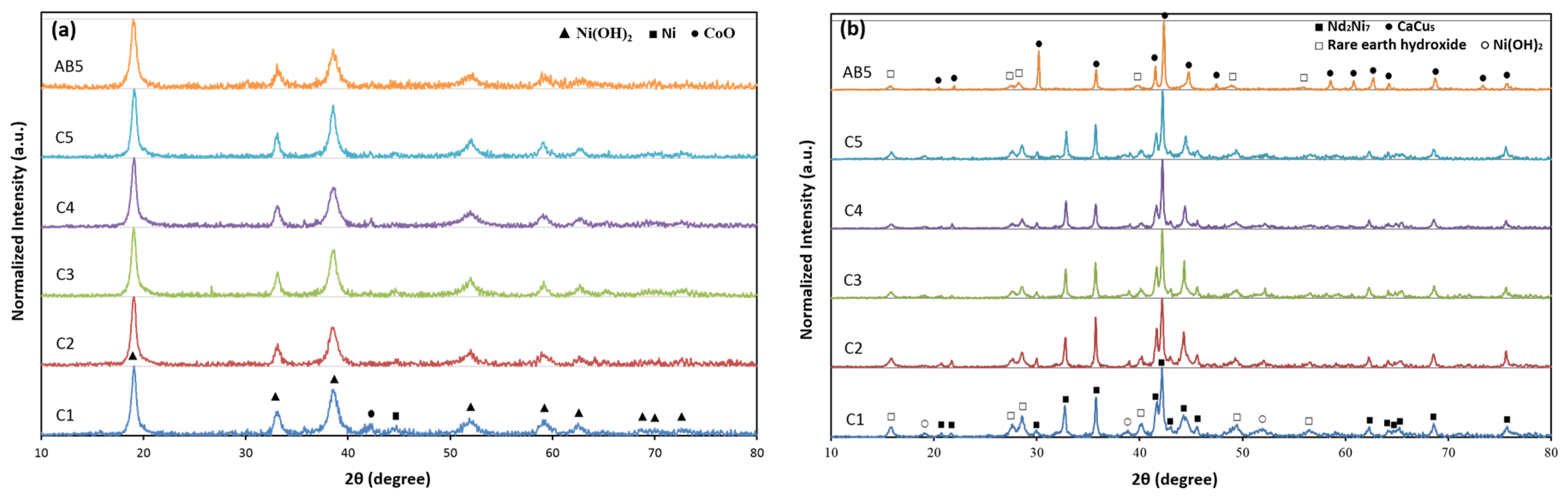
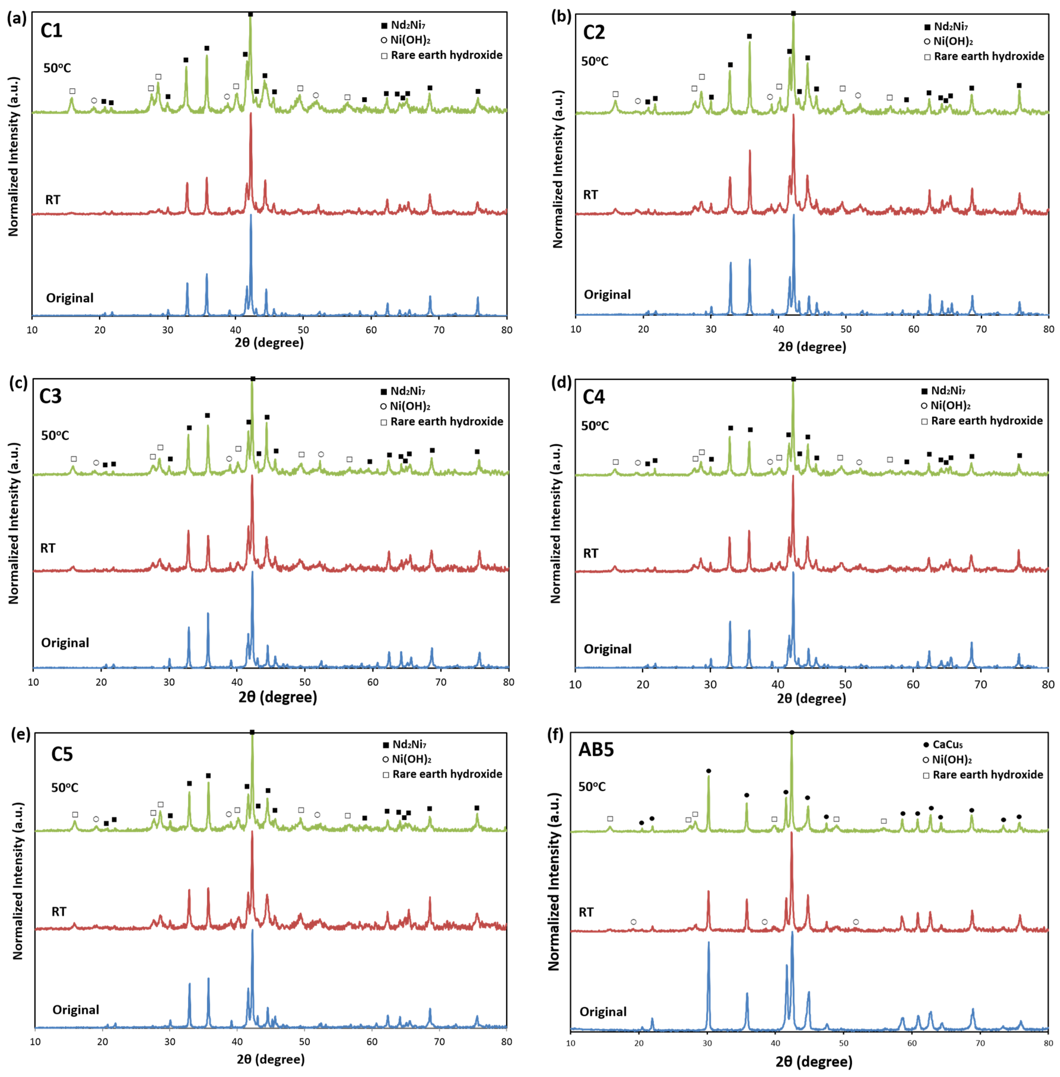
3.2. X-Ray Diffraction Structure Analysis

The XRD patterns from the cycled positive and negative electrodes are presented in Figure 2a,b, respectively. In Figure 2a, the cycled positive electrodes are found to be comprised mainly of β-Ni(OH)2 (JCPDS PDF No. 00-014-0117) [26] with a small amount of CoO (JCPDS PDF No. 00-043-1004) [27] and metallic Ni (JCPDS PDF No. 00-004-0850) [28]. Metallic Ni should originate from the debris of the Ni foam that occurs when scraping the powder off the electrode. CoO is the oxidation product of the Co powder, which was added into the positive electrode as an additive in order to form the CoOOH conduction network. There is no distinguishable peak of α-Ni(OH)2 or γ-NiOOH in the XRD patterns. The existence of α-Ni(OH)2 or γ-NiOOH often results from Al-contamination from the negative electrode [29,30] or overcharge [31,32,33,34], which may cause electrode pulverization and shorten its cycle life. In addition, no obvious differences were observed for the cycled positive electrodes for all the samples.
On the other side of the system, there are obvious signs that the negative electrodes were heavily oxidized, and peak intensities of the oxidation products are prominent for all the cycled negative electrodes. There are two main types of observed oxidation products: rare earth hydroxides and Ni(OH)2. The rare earth hydroxides include La(OH)3, Nd(OH)3, and Pr(OH)3, which have very similar 2θ-diffraction angles and their peaks overlap to form broadened peaks in the XRD patterns. Figure 3 shows the XRD patterns of the negative electrodes cycled at 50 °C and RT at the end of cycle life, in comparison with those obtained from pristine HAA alloys. As indicated by the XRD patterns, the relative peak heights of the oxidation products increase dramatically when the test temperature increases to 50 °C from RT, especially for C1, which exhibits the least oxidation among all the samples at RT.

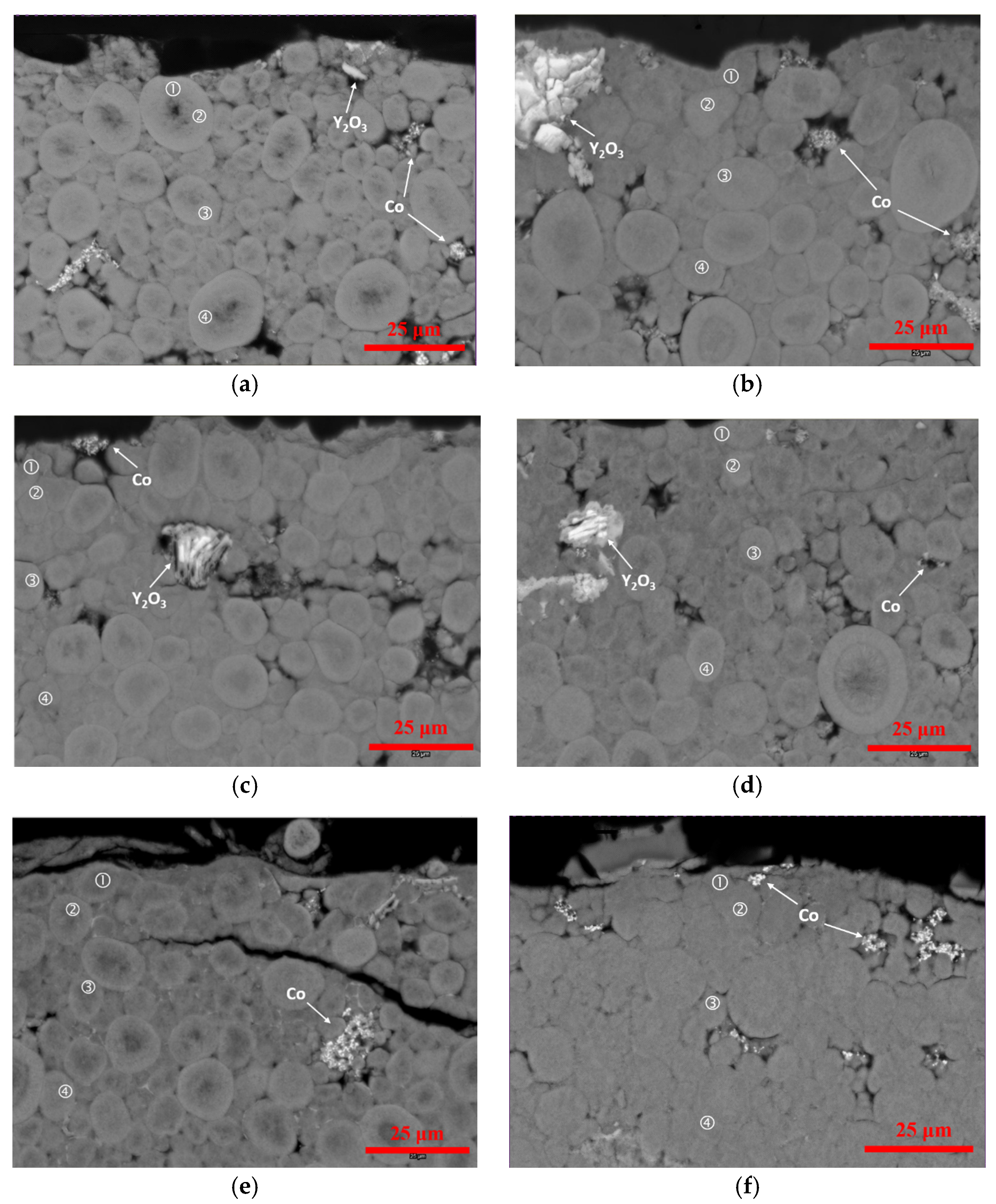
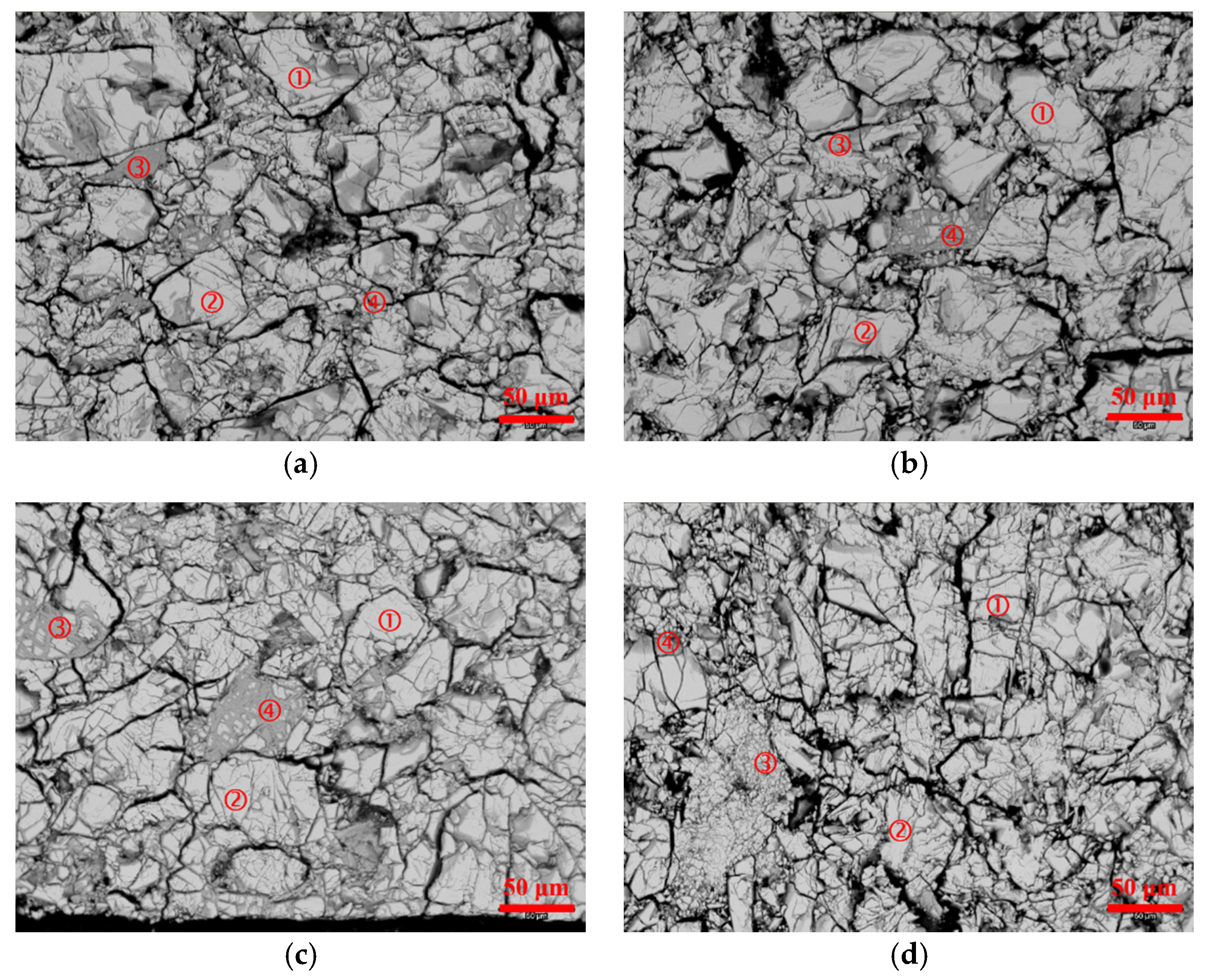
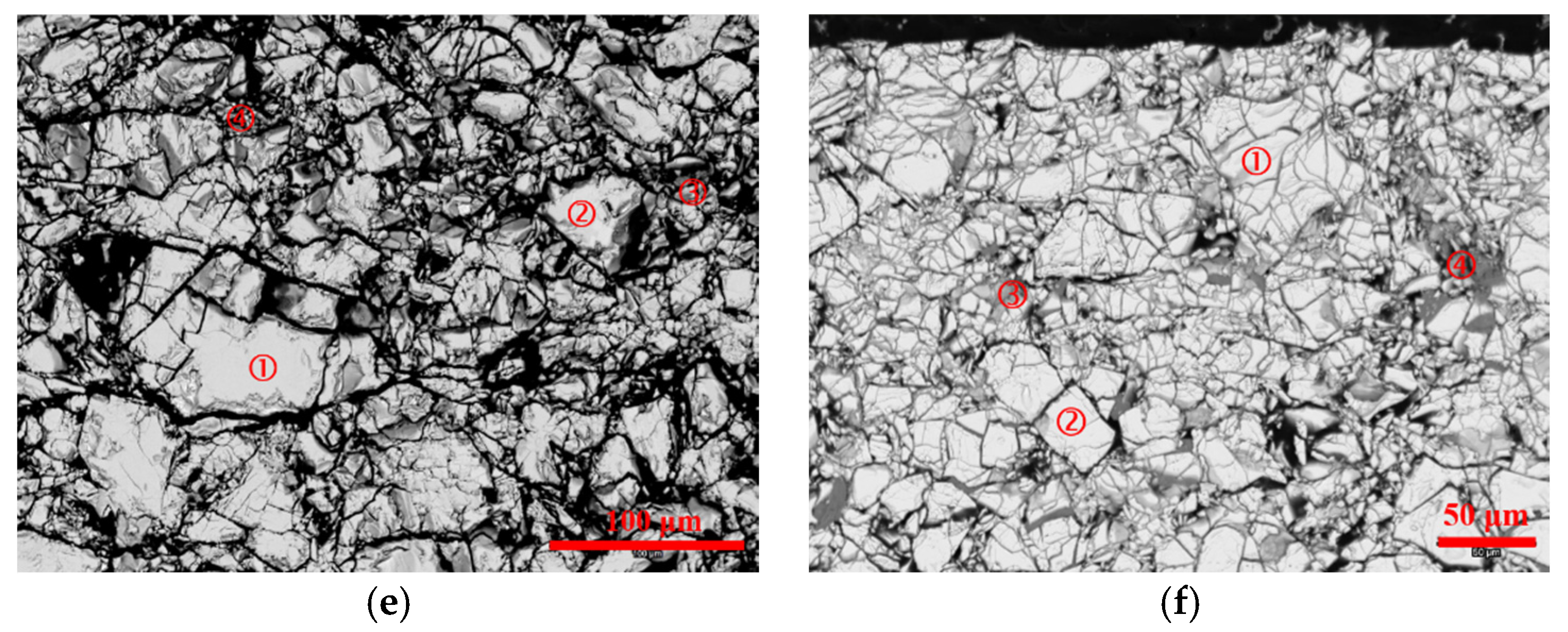
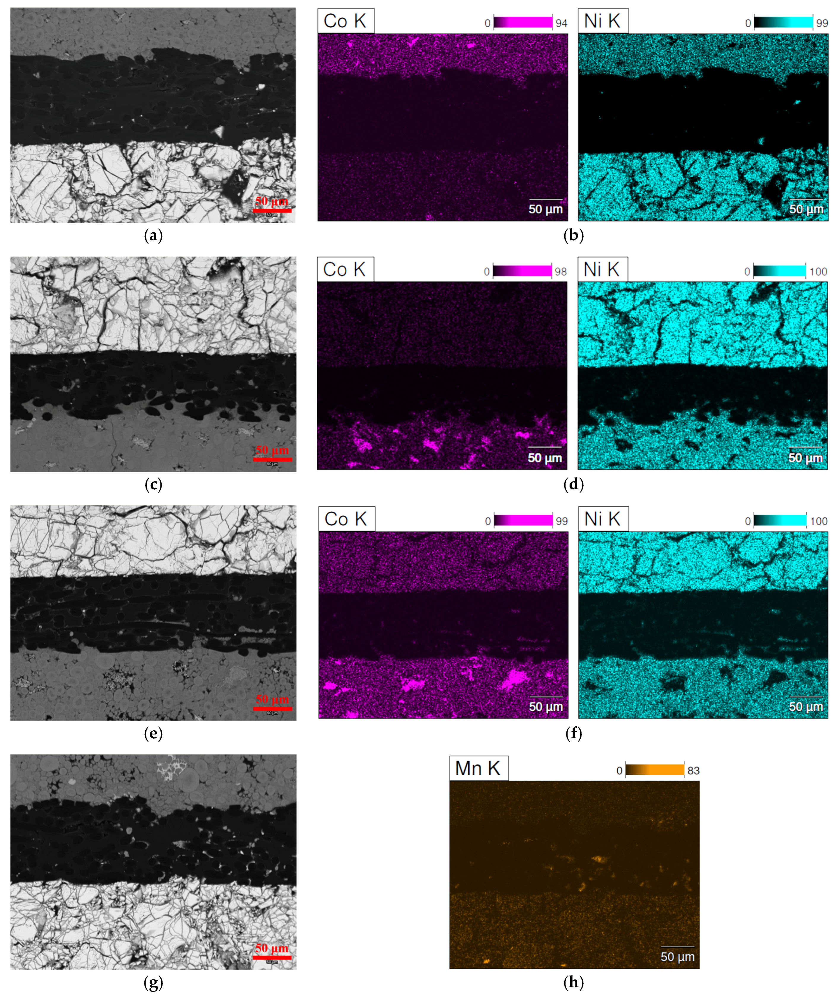
3.3. Scanning Electron Microscopy/Energy Dispersive Spectroscopy Analysis

The SEM backscattered electron images (BEIs) of the cycled positive electrodes are shown in Figure 4 and the chemical compositions at different spots on the surface of the electrode (electrode/electrolyte interface) to the bulk of the electrode, measured by EDS, are listed in Table 1. No pulverization was observed for all the samples, despite a certain degree of swelling, particularly for AB5. It is well known that Al can stabilize α-Ni(OH)2 phase, which causes a large volume expansion and will eventually lead to pulverization and capacity degradation. Al is detected in all the positive electrodes in this study. Since Al exists only in the negative electrode, where HAA is corroded, Al leaches out during cycling and migrates to the positive electrode. Also, the amount of Al found in the positive electrode may be an indication of the extent of corrosion in the negative electrode. Herein, AB5 has the highest amount of Al (6.2–7.7 at%) in the positive electrode and the most severe swelling of Ni(OH)2, as indicated by the blurry Ni(OH)2 grain boundaries in the SEM BEI micrograph. C5 has a higher amount of Al (2.8–4.1 at%) in the cycled positive electrode, compared to C1–C4. Al diffuses deep into the bulk of the positive electrode, with a slight decline in at% from Spot 1 (surface) to Spot 4 (about 50–75 μm from the surface), though it is expected that the diffusion length of Al is much larger than observed. Besides Al, Mg and Mn were also observed in the cycled positive electrodes with A2B7 and AB5 HAAs, respectively. Mg accumulates at the surface region of the cycled positive electrodes of the cells C1–C5 and does not diffuse far into the bulk, while a small amount of Mn (1.6 at%) gathers mainly at the surface region of the cycled positive electrodes of the cell AB5.
The SEM BEIs of the cycled negative electrodes are shown in Figure 5 and their chemical compositions at different spots, measured by EDS, are listed in Table 2. The spot EDS results indicate that the bright regions (Spots 1 and 2) on the BEI micrographs correspond to the un-oxidized A2B7 phase (the small amount of oxygen may originate from sample preparation and transfer for SEM), while the dark regions (Spots 3 and 4) correspond to the oxidized alloy surfaces and are characterized by a high oxygen content (high oxygen-to-metal ratio, O/M) and much lower content of Al and/or Mg (Mn) for C1–C5 (AB5). All the samples show a substantial degree of oxidation. The Co-free C1 exhibits a more severe oxidation than the low Co-content C2 and C3, which is consistent with the XRD analysis discussed above and could be one of the main causes of why C1 has a shorter cycle life than C2 and C3. Although the oxidation for C1, C2, and C3 are obvious, the pulverization for these three samples is not as severe as the high Co-content C4 and C5. Except for oxidation and pulverization, in C5, there are regions with very high O content (C5-4), which passivate the active surfaces and result in capacity loss. The secondary phases, other than A2B7, for C5 may have caused the most severe oxidation and pulverization among all the samples, which leads to a much shorter cycle life. Oxidation and pulverization are also observed for AB5 after cycling. Similar to A2B7 HAAs, there is substantially less Al and Mn in the oxidized regions of the AB5 HAA. Compared to C1–C5, the oxidation and pulverization of AB5 HAA is not severe.
The above XRD and SEM/EDS results indicate that the positive electrodes remain in good shape at the end of cycle life. No pulverization or severe swelling was observed, even though Al migrated from the negative electrode and diffuses into the bulk of the positive electrode. Thus, it is unlikely that the failure of the cells results from the degradation of the positive electrodes. On the negative electrode side, a higher degree of oxidation is observed at 50 °C for all samples, compared to cells cycled at RT, which may be a major cause of the battery failure at 50 °C. In particular, for C4 and C5, failure is closely related to the severe pulverization of the negative electrodes.
In addition to the positive and negative electrodes, the micro-shortage caused by the conducting or semiconducting deposits in the separator also contributes to the capacity loss as a result of self-discharge [35,36,37] and is examined in this work. SEM was used to study the cross-section of the positive electrode/separator/negative electrode sandwich structure at the end of cycle life. The BEI micrographs are presented in Figure 6a–d. For all the samples, the positive electrodes do not exhibit any sign of pulverization, which is consistent with our SEM observations on the surfaces of the positive electrodes (Figure 4). For Cell C1 (Figure 6a), the separator and the two electrode/separator interfaces are clean, despite some scattered debris from SEM-sample preparation (loose particles from negative electrode). The EDS elemental mapping does not show any micro-shortage network forming in the separator by any element of this battery system. In comparison with the other samples, the Co- and Ni-mapping micrographs, observed using EDS, are selected and shown in Figure 6b. It is clear that no Co- or Ni- micro-shortage network formed in the separator for Cell C1. However, the negative electrode from the same cell showed severe pulverization, which was not seen from the surface SEM study (Figure 5a). Since the positive electrode remains intact after cycling, the failure of Cell C1 is attributed to the oxidation and pulverization of the negative electrode. For Cell C3 (Figure 6c), it is obvious that the separator loses electrolyte, leading to dry-out, as seen from fact that the positive electrode materials are squeezed into the separator. Although the separator is squeezed, no clear micro-shortage networks were observed from the Co and Ni EDS mapping (Figure 6d). Thus, the failure of cell C3 is ascribed to electrolyte dry-out. For Cell C5 (Figure 6e), again the separator is embedded with debris, which strongly indicates electrolyte dry-out. In addition, EDS mapping shows a clear Co and Ni micro-shortage network (Figure 6f) across the separator. The formation of such a network is a strong indication that the negative electrode was severely corroded and Co and Ni leached out, which formed deposits on the separator surface and decreased the charge/discharge depth and cycle life. The heavy corrosion of HAA C5 can also be observed in Figure 5e, and may be related to its high Co-content, which warrants further investigation. Similar to Cell C5, a Mn-rich micro-shortage network (Figure 6h, reported before in AB5 MH alloy [38]) is observed for cell AB5, which is believed to be the main cause of failure, considering that both electrodes were in good condition. The deposits of Mn in the separator from the leach-out of Mn from the HAA AB5, as can be seen from the decreased Mn content in certain regions of the negative electrode (Table 2), decrease the cell capacity. Pulverization can be seen from the HAA AB5, which also contributes to the capacity loss.
From the analysis above, it can be concluded that, at 50 °C, the failure of the cells using Co-substituted superlattice HAAs can be mainly attributed to issues related to the separator and negative electrode, rather than the positive electrode, which differs from what is seen during RT cycling, where swelling/pulverization of the positive electrode also plays a role in cell failure [18]. Elevated temperature accelerates the electrolyte dry-out and the corrosion of HAA, which results in electrode pulverization, as well as the formation of a micro-shortage network created from leach-out elements (Co, Ni, Mn) from HAA. Cells with the low Co-content HAAs (C2 and C3) exhibit better cycle life performance compared to those with the Co-free (C1) and high Co-content HAAs (C4 and C5), which is attributed to their low degree of oxidation and pulverization properties. As a comparison, the failure of cell AB5 is attributed to the pulverization of the negative electrode and formation of a Mn-containing micro-shortage network in the separator.
The high-temperature behaviors of AB5 MH alloys have been extensively studied. Begum and his coworkers reported a decrease in capacity of a standard misch-metal based AB5 MH alloy at higher temperature and attributed it to the “instability” of the alloy [39]. Lin and his coworkers found the cycle stability and discharge capacity of a Pr-Nd-free AB5 MH alloy degrade when the temperature rises to 80 °C due to pulverization of the alloy and disintegration of the electrode [40]. Khaldi and his coworkers reported that both the corrosion current and potential of a La-only AB5 MH alloy increase with the increase of temperature [41]. Zhou and his coworkers found the needle-shaped corrosion product using SEM and correlated it to the capacity degradation at high temperature for a La-rich AB5 MH alloy [42]. The higher corrosion rate of Mg-containing A2B7 versus the Mg-free A2B7 due to the formation of Mg(OH)2 on the surface was also reported before [43]. Our findings in the failure mechanisms for AB5 and superlattice MH alloys are consistent with these reported results, but are from various analytic measurements conducted from the sealed cells, instead of HAA itself.
As for the possible solution to improve the cycle stability at an elevated temperature, Shangguan and his coworkers proposed a NaBO2 [44] and NaWO4 [45] added NaOH electrolyte to improve the capacity at 70 °C by increasing the oxygen evolution potential, but the capacity degradation remained unchanged. Adding Al [46] or Fe [47] to a Pr-Nd-free AB5 MH alloy improves its anti-corrosion capability at 60 °C as reported by researchers in Sichuan University [46]. Adding Al into the La-only AB5 alloy, reported by Balogun et al. [48], also increases its anti-corrosion capability at 50°C. Li and his coworkers also demonstrated the benefit of adding Al to increase the stability of misch-metal based AB5 MH alloy at 60 °C [49]. We also developed a surface coating of Y, Si-containing compound to stabilize the high-temperature cycle performance of AB5 and Mg-containing superlattice MH alloys, and further studies are ongoing.

4. Conclusions

The failure mechanisms of cells using Co-substituted A2B7 superlattice HAAs cycled at 50 °C were assessed. The positive electrodes remained in good condition at the end of cycle life for all samples, as the XRD patterns showed no signs of α-Ni(OH)2 or γ-NiOOH formation and SEM exhibited no signs of pulverization or severe swelling. Thus, the positive electrode was excluded as a cause of battery failure at 50 °C. For the cells with Co-substituted A2B7 HAAs, the inferior performance at 50 °C can be attributed to accelerated dry-out of electrolyte and deterioration of the negative electrode. In these cases, the negative electrodes of the cycled cells at 50 °C exhibit much more severe oxidation than those at RT, as indicated by XRD. At 50 °C, the incorporation of a small amount of Co (C2 and C3) in A2B7 leads to mitigated oxidation/pulverization and, therefore, longer cycle life compared to the Co-free C1. However, further increases in Co-content leads to more severe oxidation/pulverization and the formation of micro-shortage networks in the separator, which has a negative effect on cycle life.

Acknowledgments

The authors would like to thank the following from BASF-Ovonic for technical assistance: Alan Chen, Ryan Blankenship, Nathan English, and Su Cronogue.

Author Contributions

Tiejun Meng designed the experiments and analyzed test results. Kwo-hsiung Young interpreted the data. John Koch performed the cell disassembly. Taihei Ouchi performed the XRD analysis. Shigekazu Yasuoka designed and obtained the test samples.

Conflicts of Interest

The authors declare no conflict of interest.

Abbreviations

HAAHydrogen absorbing alloy
Ni/MHNickel/metal hydride
MHMetal hydride
XRDX-ray diffraction
SEMScanning electron microscopy
EDSEnergy dispersive spectroscopy
ICPInductively coupled plasma
BEIBackscattered electron image
O/MOxygen to metal ratio

References

  1. Zelinsky, M.; Koch, J.; Fetcenko, M. Heat Tolerant NiMH Batteries for Stationary Power. Available online: www.battcon.com/PapersFinal2010/ZelinskyPaper2010Final_12.pdf (accessed on 28 March 2016).
  2. Zelinsky, M.; Koch, J. Batteries and Heat—A Recipe for Success? Available online: www.battcon.com/PapersFinal2013/16-Mike%20Zelinsky%20-%20Batteries%20and%20Heat.pdf (accessed on 28 March 2016).
  3. Young, K.; Ng, K.Y.S.; Bendersky, L. A Technical Report of the Robust Affordable Next Generation Energy Storage System-BASF Program. Batteries 2016, 2. [Google Scholar] [CrossRef]
  4. VARTA Microbattery GmbH. Powerful High Temperature NiMH Batteries −20/+85 °C, 2008. Available online: http://www.varta-microbattery.com/applications/mb_data/documents/product_information/PI20081111_Electronica_Ni-MH_High_Temp_en.pdf (accessed on 28 March 2016).
  5. Kai, T.; Ishida, J.; Yasuoka, S.; Takeno, K. The Effect of Nickel-Metal Hydride Battery’s Characteristics with Structure of the Alloy. In Proceedings of the 54th Battery Symposium in Japan, Osaka, Japan, 7–9 October 2013; p. 210.
  6. Li, W.; Campion, C.; Lucht, B.L.; Ravdel, B.; DiCarlo, J.; Abraham, K.M. Additives for stabilizing LiPF6-based electrolytes against thermal decomposition. J. Electrochem. Soc. 2005, 152, A1361–A1365. [Google Scholar] [CrossRef]
  7. Lee, H.H.; Wan, C.C.; Wang, Y.Y. Thermal stability of the solid electrolyte interface on carbon electrodes of lithium batteries. J. Electrochem. Soc. 2004, 151, A542–A547. [Google Scholar] [CrossRef]
  8. Yang, H.; Bang, H.; Amine, K.; Prakash, J. Investigations of the exothermic reactions of natural graphite anode for Li-ion batteries during thermal runaway. J. Electrochem. Soc. 2005, 152, A73–A79. [Google Scholar] [CrossRef]
  9. Hammami, A.; Raymond, N.; Armand, M. Lithium-ion batteries: Runaway risk of forming toxic compounds. Nature 2003, 424, 635–636. [Google Scholar] [CrossRef] [PubMed]
  10. Wang, Q.; Ping, P.; Zhao, X.; Chu, G.; Sun, J.; Chen, C. Thermal runaway caused fire and explosion of lithium ion battery. J. Power Sources 2012, 208, 210–224. [Google Scholar] [CrossRef]
  11. Fierro, C.; Zallen, A.; Koch, J.; Fetcenko, M.A. The influence of nickel-hydroxide composition and microstructure on the high-temperature performance of nickel metal hydride batteries. J. Electrochem. Soc. 2006, 153, A492–A496. [Google Scholar] [CrossRef]
  12. Young, K.; Yasuoka, S. Capacity degradation mechanisms in nickel/metal hydride batteries. Batteries 2016, 2. [Google Scholar] [CrossRef]
  13. Young, K.; Chao, B.; Liu, Y.; Nei, J. Microstructures of the oxides on the activated AB2 and AB5 metal hydride alloys surface. J. Alloys Compd. 2014, 616, 97–104. [Google Scholar] [CrossRef]
  14. Young, K.; Huang, B.; Regmi, R.K.; Lawes, G.; Liu, Y. Comparisons of metallic clusters imbedded in the surface oxide of AB2, AB5, and A2B7 alloys. J. Alloys Compd. 2010, 506, 831–840. [Google Scholar] [CrossRef]
  15. Young, K.; Wu, A.; Qiu, Z.; Tan, J.; Mays, W. Effects of H2O2 addition to the cell balance and self-discharge of Ni/MH batteries with AB5 and A2B7 alloys. Int. J. Hydrog. Energy 2012, 37, 9882–9891. [Google Scholar] [CrossRef]
  16. Zhou, X.; Young, K.; West, J.; Regalado, J.; Cherisol, K. Degradation mechanisms of high-energy bipolar nickel metal hydride battery with AB5 and A2B7 alloys. J. Alloys Compd. 2013, 580, S373–S377. [Google Scholar] [CrossRef]
  17. Young, K.; Wong, D.F.; Wang, L.; Nei, J.; Ouchi, T.; Yasuoka, S. Mn in misch-metal based superlattice metal hydride alloy—Part 2 Ni/MH battery performance and failure mechanism. J. Power Sources 2015, 277, 433–442. [Google Scholar] [CrossRef]
  18. Wang, L.; Young, K.; Meng, T.; English, N.; Yasuoka, S. Partial substitution of cobalt for nickel in mixed rare earth metal based superlattice hydrogen absorbing alloy—Part 2 Battery performance and failure mechanism. J. Alloys Compd. 2016, 664, 417–427. [Google Scholar] [CrossRef]
  19. Young, K.; Nei, J. The current status of hydrogen storage alloy development for electrochemical applications. Materials 2013, 6, 4574–4608. [Google Scholar] [CrossRef]
  20. Zhang, Y.; Zhao, D.; Li, B.; Zhao, X.; Wu, Z.; Wang, X. Microstructures and electrochemical characteristics of the La0.75Mg0.25Ni2.5Mx (M = Ni, Co; x = 0–1.0) hydrogen storage alloys. Int. J. Hydrog. Energy 2008, 33, 1868–1875. [Google Scholar] [CrossRef]
  21. Reilly, J.J.; Adzic, G.D.; Johnson, J.R.; Vogt, T.; Mukerjee, S.; Mcbreen, J. The correlation between composition and electrochemical properties of metal hydride electrodes. J. Alloys Compd. 1999, 293–295, 569–582. [Google Scholar] [CrossRef]
  22. Liu, J.; Yang, Y.; Li, Y.; Yu, P.; He, Y.; Shao, H. Comparative study of LaNi4.7M0.3 (M = Ni, Co, Mn, Al) by powder microelectrode technique. Int. J. Hydrog. Energy 2007, 32, 1905–1910. [Google Scholar] [CrossRef]
  23. Young, K.; Wong, D.F.; Wang, L.; Nei, J.; Ouchi, T.; Yasuoka, S. Mn in misch-metal based superlattice metal hydride alloy—Part 1 Structural, hydrogen storage and electrochemical properties. J. Power Sources 2015, 277, 426–432. [Google Scholar] [CrossRef]
  24. Wang, L.; Young, K.; Meng, T.; Ouchi, T.; Yasuoka, S. Partial substitution of cobalt for nickel in mixed rare earth metal based superlattice hydrogen absorbing alloy—Part 1 Structural, hydrogen storage and electrochemical properties. J. Alloys Compd. 2016, 660, 407–415. [Google Scholar] [CrossRef]
  25. Nei, J.; Young, K.; Rotarov, D. Studies on MgNi-based metal hydride electrode with aqueous electrolytes composed of various hydroxides. Batteries 2016, 2. [Google Scholar] [CrossRef]
  26. JCPDS-International Centre for Diffraction Data®. Powder Diffraction File (PDF) No. 00-014-0117; JCPDS: Newtown Square, PA, USA, 2015. [Google Scholar]
  27. JCPDS-International Centre for Diffraction Data®. Powder Diffraction File (PDF) No. 00-043-1004; JCPDS: Newtown Square, PA, USA, 2015. [Google Scholar]
  28. JCPDS-International Centre for Diffraction Data®. Powder Diffraction File (PDF) No. 00-004-0850; JCPDS: Newtown Square, PA, USA, 2015. [Google Scholar]
  29. Liu, B.; Wang, X.Y.; Yuan, H.T.; Zhang, Y.S.; Song, D.Y.; Zhou, X.Y. Physical and electrochemical characteristics of aluminum-substituted nickel hydroxide. J. Appl. Electrochem. 1999, 29, 855–860. [Google Scholar] [CrossRef]
  30. Liu, B.; Yuan, H.; Zhang, T. Impedance of Al-substituted α-nickel hydroxide electrodes. Int. J. Hydrog. Energy 2004, 29, 453–458. [Google Scholar] [CrossRef]
  31. Bode, H.; Dehmelt, K.; Witte, J. Zur kenntnis der nickelhydroxidelektrode—I. Über das nickel (II)-hydroxidhydrat. Electrochim. Acta 1966, 11, 1079–1087. (In German) [Google Scholar] [CrossRef]
  32. Oliva, P.; Leonardi, J.; Laurent, J.F.; Delmas, C.; Braconnier, J.J.; Figlarz, M.; Fievet, F.; de Guibert, A. Review of the structure and the electrochemistry of nickel hydroxides and oxy-hydroxides. J. Power Sources 1982, 274, 8, 229–255. [Google Scholar] [CrossRef]
  33. Van der Ven, A.; Morgan, D.; Meng, Y.S.; Ceder, G. Phase stability of nickel hydroxides and oxyhydroxides. J. Electrochem. Soc. 2006, 153, A210–A215. [Google Scholar] [CrossRef]
  34. Miao, C.; Zhu, Y.; Huang, L.; Zhao, T. The relationship between structural stability and electrochemical performance of multi-element doped alpha nickel hydroxide. J. Power Sources 2015, 274, 186–193. [Google Scholar] [CrossRef]
  35. Guo, H.; Qiao, Y.; Zhang, H. Fast determination of micro short circuit in sintered MH-Ni battery. Chin. J. Power Sources 2010, 34, 608–609. [Google Scholar]
  36. Shinyama, K.; Magari, Y.; Kumagae, K.; Nakamura, H.; Nohma, T.; Takee, M.; Ishiwa, K. Deterioration mechanism of nickel metal-hydride batteries for hybrid electric vehicles. J. Power Sources 2005, 141, 193–197. [Google Scholar] [CrossRef]
  37. Zhu, W.H.; Zhu, Y.; Tatarchuk, B.J. Self-discharge characteristics and performance degradation of Ni-MH batteries for storage applications. Int. J. Hydrog. Energy 2014, 39, 19789–19798. [Google Scholar] [CrossRef]
  38. Shinyama, K.; Magari, Y.; Akita, H.; Kumagae, K.; Nakamura, H.; Matsuta, S.; Nohma, T.; Takee, M.; Ishiwa, K. Investigation into the deterioration in storage characteristics of nickel metal-hydride batteries during cycling. J. Power Sources 2005, 143, 265–269. [Google Scholar] [CrossRef]
  39. Begum, S.N.; Muralidharan, V.S.; Basha, C.A. Electrochemical investigations and characterization of a metal hydride alloy (MmNi3.6Al0.4Co0.7Mn0.3) for nickel metal hydride batteries. J. Alloys Compd. 2009, 467, 124–129. [Google Scholar] [CrossRef]
  40. Lin, J.; Cheng, Y.; Liang, F.; Sun, L.; Yin, D.; Wu, Y.; Wang, L. High temperature performance of La0.6Ce0.4Ni3.45Co0.75Mn0.7Al0.1 hydrogen storage alloy for nickel/metal hydride batteries. Int. J. Hydrog. Energy 2014, 39, 13231–13239. [Google Scholar] [CrossRef]
  41. Khaldi, C.; Boussami, S.; Tliha, M.; Azizi, S.; Fenineche, N.; El-kedim, O.; Mathlouthi, H.; Lamloumi, J. The effect of the temperature on the electrochemical properties of the hydrogen storage alloy for nickel-metal hydride accumulators. J. Alloys Compd. 2013, 574, 59–66. [Google Scholar] [CrossRef]
  42. Zhou, H.; Wang, P.; Wang, Z.; Zou, R.; Ni, C. Influence of temperature on self-discharge and high-rate discharge characteristics of La-rich AB5-based MH alloy electrode. Mater. Sci. Forum 2010, 654–656, 2835–2838. [Google Scholar] [CrossRef]
  43. Monnier, J.; Chen, H.; Joiret, S.; Bourgon, J.; Latroche, M. Identification of a new pseudo-binary hydroxide during calendar corrosion of (La, Mg)2Ni7-type hydrogen storage alloys for nickel-metal hydride batteries. J. Power Sources 2014, 266, 162–169. [Google Scholar] [CrossRef]
  44. Shangguan, E.; Wang, J.; Li, J.; Dan, G.; Chang, Z.; Yuan, X.; Wang, H. Enhancement of the high-temperature performance of advanced nickel-metal hydride batteries with NaOH electrolyte containing NaBO2. Int. J. Hydrog. Energy 2013, 38, 10616–10624. [Google Scholar] [CrossRef]
  45. Shangguan, E.; Li, J.; Chang, Z.; Tang, H.; Li, B.; Yuan, X.; Wang, H. Sodium tungstate as electrolyte additive to improve high-temperature performance of nickel-metal hydride batteries. Int. J. Hydrog. Energy 2013, 38, 5153–5158. [Google Scholar] [CrossRef]
  46. Zhou, W.; Ma, Z.; Wu, C.; Zhu, D.; Huang, L.; Chen, Y. The mechanism of suppressing capacity degradation of high-Al AB5-type hydrogen storage alloys at 60 °C. Int. J. Hydrog. Energy 2016, 41, 1801–1810. [Google Scholar] [CrossRef]
  47. Chao, D.; Zhong, C.; Ma, Z.; Yang, F.; Wu, Y.; Zhu, D.; Wu, C.; Chen, Y. Improvement in high-temperature performance of Co-free high-Fe AB5-type hydrogen storage alloys. Int. J. Hydrog. Energy 2012, 37, 12375–12383. [Google Scholar]
  48. Balogun, M.; Wang, Z.; Huang, H.; Yao, Q.; Deng, J.; Zhou, H. Effect of high and low temperature on the electrochemical performance of LaNi4.4−xCo0.3Mn0.3Alx hydrogen storage alloys. J. Alloys Compd. 2013, 579, 438–443. [Google Scholar] [CrossRef]
  49. Li, Z.; Rei, Y.; Han, F. Influence of small amount of addition elements on electrochemical and high temperature performance of La-riched RE-based hydrogen storage materials. Chin. J. Rare Metals 2002, 26, 47–50. [Google Scholar]
Figure 1. (a) Cycle life (the number of cycles when the discharge capacity drops to 70% of the original capacity) as a function of Co-content in the superlattice A2B7 hydrogen absorbing alloys (HAAs) at room temperature (RT, 20 °C) and 50 °C. The blue dotted line and red dashed line denote the cycle life for AB5 at RT and 50 °C, respectively. (b) Capacity vs. cycle number for cells with HAAs C1–C5 and AB5 at 50 °C (adapted from [24]).
Batteries 02 00020 g001
Figure 2. X-ray diffraction (XRD) patterns of the cycled (a) positive and (b) negative electrodes for cells with HAAs C1–C5 and AB5 at the end of cycle life.
Batteries 02 00020 g002
Figure 3. Comparison of the XRD patterns of the negative electrodes before cycling (original) and after cycling at RT (20 °C) and 50 °C containing HAAs (a) C1; (b) C2; (c) C3; (d) C4; (e) C5; and (f) AB5.
Batteries 02 00020 g003
Figure 4. Scanning electron microscopy (SEM) backscattered electron image (BEI) micrographs of the positive electrodes at the end of cycle life at 50 °C for (a) C1; (b) C2; (c) C3; (d) C4; (e) C5; and (f) AB5.
Batteries 02 00020 g004
Figure 5. SEM BEI micrographs of the negative electrodes at the end of cycle life at 50 °C for HAAs (a) C1; (b) C2; (c) C3; (d) C4; (e) C5; and (f) AB5.
Batteries 02 00020 g005aBatteries 02 00020 g005b
Figure 6. SEM BEI micrographs and selected EDS elemental mappings of the cross-sections of cells (a,b) C1; (c,d) C3; (e,f) C5; and (g,h) AB5.
Batteries 02 00020 g006
Table 1. Chemical compositions in at% of selected spots (as shown in Figure 4) determined by energy dispersive spectroscopy (EDS) in the positive electrodes at the end of cycle life. ND denotes non-detectable.
LocationNiCoZnYAlMgMn
C1-178.2162.0ND2.51.3ND
C1-277.315.72.4ND3.41.2ND
C1-378.417.02.1ND2.5NDND
C1-477.518.01.9ND2.6NDND
C2-178.114.42.10.43.61.3ND
C2-278.016.62.40.32.7NDND
C2-378.216.82.30.22.4NDND
C2-478.816.12.40.42.4NDND
C3-175.117.31.80.22.92.6ND
C3-274.618.02.20.32.72.1ND
C3-376.418.42.40.32.5NDND
C3-476.818.22.40.22.30.1ND
C4-177.215.22.10.22.82.5ND
C4-278.115.01.90.32.52.2ND
C4-378.316.82.40.32.2NDND
C4-478.416.42.50.22.5NDND
C5-178.412.41.7ND4.13.4ND
C5-279.313.21.7ND3.22.6ND
C5-380.213.12.20.23.60.9ND
C5-481.513.71.90.12.8NDND
AB5-174.014.91.70.27.6ND1.6
AB5-277.512.41.8ND7.7ND0.5
AB5-375.915.02.2ND6.8ND0.2
AB5-477.014.82.00.16.2NDND
Table 2. Chemical compositions in at% of selected spots (as shown in Figure 5) determined by EDS in the negative electrodes at the end of cycle life. B/A is the ratio of the sum of the atomic percentages of A-site atoms (La, Ce, Pr, Nd, and Mg) over that of the B-site atoms (Ni, Co, Al, and Mn). O/M denotes the ratio of oxygen to total metallic content. ND denotes non-detectable.
LocationLaCePrNdNiCoAlMgMnOB/AO/M
C1-14.1ND7.97.873.1ND4.22.9NDND3.41ND
C1-23.9ND7.97.87.6ND4.02.9NDND3.45ND
C1-310.2ND0.32.064.0ND0.2NDND23.45.140.31
C1-42.3ND3.53.564.1ND0.20.2ND26.26.770.36
C2-13.6ND7.27.166.62.33.32.8ND7.13.490.08
C2-23.4ND7.67.466.42.13.32.6ND7.23.420.08
C2-32.0ND4.95.363.32.70.40.5ND20.95.230.26
C2-42.2ND4.85.459.32.1ND0.3ND25.94.830.35
C3-13.3ND7.57.562.94.43.03.0ND8.33.300.09
C3-23.4ND7.37.262.84.43.42.8ND8.83.410.10
C3-32.7ND6.36.152.53.70.71.1ND26.93.510.37
C3-42.8ND5.65.851.34.20.60.6ND29.23.790.41
C4-13.4ND7.47.261.76.93.22.9ND7.23.440.08
C4-23.7ND7.17.059.56.64.03.0ND9.13.370.10
C4-33.3ND7.16.958.06.02.62.9ND13.23.300.15
C4-42.2ND5.55.757.87.13.10.5ND18.14.890.22
C5-13.2ND7.17.359.08.83.23.2ND8.13.410.09
C5-24.5ND7.26.958.38.83.82.7ND7.83.330.08
C5-32.7ND4.84.660.47.22.61.8ND15.85.050.19
C5-47.5ND14.414.819.02.12.135.0ND36.50.580.58
AB5-19.84.10.70.757.312.44.0ND6.53.65.240.04
AB5-29.74.20.60.658.912.54.2ND5.13.35.340.03
AB5-38.03.10.30.344.810.50.5ND0.730.54.830.44
AB5-41.00.40.20.21.90.50.6ND57.637.633.670.60

