Article

Freeze-Drying-Assisted Preparation of High-Compaction-Density LiMn0.69Co0.01Fe0.3PO4 Cathode Materials with High-Capacity and Long Life-Cycle for Lithium Ion Batteries

1
School of Chemical Engineering, University of Science and Technology Liaoning, Anshan 114051, China
2
State Laboratory of Surface and Interface Science and Technology, College of Materials and Chemical Engineering, Zhengzhou University of Light Industry, Zhengzhou 450002, China
3
School of Chemical Engineering, Nanjing University of Science and Technology, Nanjing 210094, China
*
Authors to whom correspondence should be addressed.
These authors contributed equally to this work.
Batteries 2024, 10(4), 114; https://doi.org/10.3390/batteries10040114
Submission received: 2 February 2024 / Revised: 1 March 2024 / Accepted: 12 March 2024 / Published: 25 March 2024
(This article belongs to the Special Issue Materials and Interface Designs for Batteries)

Abstract

:
As a successor to LiFePO4, the research interest in LiMn1−yFeyPO4 has been sustained due to its higher working voltage and safety features. However, its further application is limited by the low compaction density caused by uncontrolled particle size. In this study, the high-quality LiMn0.69Co0.01Fe0.3PO4 (LMFP) materials were prepared using the freeze-drying method to process the LMFP precursor synthesized through a solvothermal crystallization method followed by a calcination process at different temperatures (400–550 °C). The results demonstrate that the obtained particles exhibit a spheroidal shape with a low specific surface area after secondary crystallization calcination at 700 °C. The compaction density increased from 1.96 g/cm3 for LMFP precursor (LMFP-M1) to 2.18, 2.27, 2.34, and 2.43 g/cm3 for samples calcined at 400, 450, 500 and 550 °C, respectively, achieving a maximum increase of 24%. The full cell constructed with the high-compaction-density material calcined at 500 °C displayed discharge capacities of 144.1, 143.8, and 142.6 mAh/g at 0.5, 1, and 3 C rates, respectively, with a retention rate of 99% at 3 C rate. After undergoing charging and discharging cycles at a rate of 1 C for up to 800 cycles, the capacity retention rate was found to be 90%, indicating an expected full cell life span exceeding 2500 cycles.

1. Introduction

Over the past two decades, olivine LiFePO4 has emerged as a prominent cathode material for lithium ion batteries (LIBs), especially in applications such as electric vehicles and large-scale energy storage systems, owing to its notable safety profile, minimal environmental impact, and affordability [1,2,3,4,5]. In particular, for the year of 2023, among the three mainstream power batteries (LiFePO4, LiNiCoMnO2, and LiMnO2), 67.3% of the power batteries installed in domestic new energy vehicles were LiFePO4 batteries, based on the data reported by the China Automotive Battery Innovation Alliance. As for the high demand for electric vehicle cruise range per charge, further boosting the energy density of LiFePO4 batteries suffers from the limitation of available battery assembly technology and lower operating potential (3.4 V vs. Li/Li+), as well as the theoretical capacity of 170 mAh/g (578 Wh kg−1) [6,7,8]. In view of the highly stable olivine framework, one way to increase the energy density is the replacement of Fe by Mn to form LiMnPO4 or LiMn1−yFeyPO4. As shown in Figure 1a, the substituted benefit is that the working voltage of LiMnPO4 can be increased to about 4.1 V (vs. Li/Li+), the theoretical energy density is 21% higher than LiFePO4, equal to LiNi0.5Co0.2Mn0.3O2, and up to 700 Wh kg−1 [9,10,11,12]. Although LiMn1−yFeyPO4 does not reach the high theoretical energy density of sulfur (2600 Wh kg−1 and 2800 Wh L−1) [13,14], and the ultra-high theoretical specific energy of Li2O2 (3458 Wh kg−1) [15], in the short term, LiMn1−yFeyPO4 is the most promising material to replace the three main materials in the existing commercialized power battery market due to its excellent overall performance.
Regrettably, LiMnPO4 exhibits lower electronic conductivity and lithium ion diffusivity in comparison to LiFePO4 [16,17]. The substantial kinetic discrepancies between them originate from inherent characteristics, encompassing crystallographic features and transport properties [18]. A critical feature of the structure of LiMnPO4 is the isolation of the Mn–O octahedron by the P–O tetrahedron, distinct from the continuous M–O network observed in LiMn2O4. The robust covalent bonding within the P–O framework impedes Li+ ions from traversing through the PO43− tetrahedral sites, thereby directing Li+ ion transport predominantly along the b-axis, following a one-dimensional diffusion pathway [12,19]. The deposition/stripping dynamics adhere to a biphasic principle, marked by a pronounced lattice disparity from the MnPO4 to LiMnPO4 phases. This divergence not just imposes a considerable energy impediment to the exchange of lithium ions at the interphase boundary but amplifies the energy requisite of electronic transitions [20,21,22]. The observed phenomena can be owed to the electronic–lattice interactions surrounding the ions of Mn3+, where a pronounced Jahn–Teller effect significantly confines the polaron gap, thereby rapidly increasing the polaron’s effective mass. The augmented effective polaronic mass at the sites of Mn3+, in conjunction with the substantial number of localized lattice distortions, leads to diminished kinetic rates and increased internal friction. This effect is manifested both within the body structure of a crystal as well as at the phase boundary of LiMnPO4/MnPO4, which is featured by lattice mismatch, potentially obstructing the one-dimensional lithium ion diffusion pathway [23,24,25]. Therefore, the optimistic perspectives for LiMnPO4 as a practical cathode have not been widely accepted. Considering the advantages of LiFePO4 and LiMnPO4, a compromise is that Mn is used to replace partial Fe ions from the olivine LiFePO4, thereby forming LiMn1−yFeyPO4 [26,27]. Subsequent to ab initio calculations, it has been determined that the substitution of Mn with Fe enhances the mutual solubility of LiMn1−yFeyPO4 and Mn1−yFeyPO4, leading to an enlargement of the single-phase region and a reduction in the two-phase region. The extent of the single-phase region is contingent upon the Fe/(Fe+Mn) ratio, with the broadest extent of solid solution observed when the ions of Fe substitution reach 15–30 mol% [20,28]. Although LiMn1−yFeyPO4 possesses the above-mentioned advantages, it still has some unsolved issues including particle size control, low compaction density, electron conductivity, ionic diffusion, and carbon coating technology [29,30,31,32] (Figure 1a,c). The low tap density limits its application in power batteries. However, the compaction density of the material is related to the primary particle size and the pores between the particles. Effectively increasing the primary particle size and reducing the pores between particles can significantly enhance the material’s compaction density [27]. In our previous research, we employed a solvothermal method to regulate the particle size of LiMn1−yFeyPO4, ensuring preferential growth along the (010) crystal planes through crystal orientation control techniques [33]. Furthermore, we modified the LMFP material through Co doping and carbon coating techniques. The results not only significantly enhanced the kinetic properties but also successfully increased the particle size, thereby improving the material’s compaction density. However, the prepared LMFP has limited potential in improving the material’s compaction density. The LMFP samples have elongated and rod-like particles with high aspect ratios, which tend to form larger voids during the stacking process, leading to a challenge in further compaction of the material even under high external forces [34,35]. In contrast, spherical LMFP particles exhibited higher tap density and significant improvements in flowability, dispersibility, and processability. These unique features are crucial for preparing high-quality cathode material slurries, optimizing electrode coating processes, and enhancing the overall performance of electrode sheets [36,37,38].
Figure 1. (a) The LiMn1−yFeyPO4 specific energy density taken from Refs. [8,12]; (b) Comprehensive performance taken from Refs. [8,29] and (c) electrochemical performance comparison radar chart of LiMn1−yFeyPO4, LFP, NCM and LMO taken from Refs. [20,30]; (d) the schematic diagram of the preparation process.
Batteries 10 00114 g001
Herein, we have developed an innovative freeze-drying-assisted method to enhance the particle size and morphology of LMFP [32,39,40,41]. By precisely controlling the crystal growth process, our results demonstrate successful spherification of particles with reduced surface area and minimized gaps between smaller particles. This approach effectively improves material compaction density while maintaining its nanoscale single-crystal structure to preserve high dynamic properties, which is advantageous for achieving enhanced compaction density. Furthermore, a comprehensive evaluation of electrochemical performance confirms that our optimized LMFP cathode material exhibits superior charge–discharge cycling properties at high rates. Overall, this work presents an effective strategy for enhancing both energy density and cycling stability in LMFP cathode materials.

2. Materials and Methods

2.1. Materials and Synthesis

All raw materials used, including lithium hydroxide, ferrous sulfate, manganese chloride, cobalt sulfate, and phosphoric acid, were provided by Sinopharm Chemical Reagent Co., Ltd., Shanghai, China and were of analytical purity. The LMFP cathode material was synthesized using the solvothermal method and ethylene glycol served as the solvent. The molar ratios of LiOH·H2O, divalent metal salts (MnCl2·4H2O, CoSO4·7H2O, FeSO4·7H2O) and H3PO4 were established at 3:1(0.69:0.01:0.3):1. The detail procedures are as follows: 5.5 g MnCl2·4H2O, 0.12 g Co(NO3)2∙6H2O, 3.4 g FeSO4·7H2O, and ethylene glycol (a volume of 80 mL) were then mechanically stirred, forming solution A. A total of 5.1 g of LiOH·H2O dissolves in 80 mL ethylene glycol, labelled as solution B. Then, adding 5.96 g of H3PO4 to solution B formed the mixed solution C. Gradually, solution C was added into solution A by stirring for 30 min, and then it was transferred into a 200 mL autoclave and heated at 180 °C for 8 h. Subsequently, the solution was allowed to cool to room temperature, and the sample was obtained afterwards with centrifugal filtration. The LMFP precursor powders (named LMFP-M1) were dried in a freeze dryer.
The LMFP-M1 powder, under argon protection, was placed in a tubular furnace. The temperature was increased gradually by 5 °C/min to maintain 400, 450, 500, and 550 °C, each for 4 h (the samples were named LMFP-400, LMFP-450, LMFP-500, and LMFP-550). Subsequently, 8% sucrose (by mass) was added to LMFP-M1, LMFP-400, LMFP-450, LMFP-500, and LMFP-550, then ground and dried. The aforementioned mixtures were conveyed to a tubular furnace and subjected to heating under an argon atmosphere at a rate of 5 °C/min up to 700 °C, whereupon this temperature was maintained for a duration of 4 h. The samples were then naturally cooled to room temperature inside the furnace, resulting in carbon-coated LMFP black powder (named LMFP-M1/C, LMFP-400/C, LMFP-450/C, LMFP-500/C, and LMFP-550/C, respectively) (Figure 1d).

2.2. Characterization

Material characterization tests in this study were conducted on the AXS D8 Advance instrument from Bruker, employing Cu-Kα radiation, with a λ of 1.5406 Å, and a scan angles from 10° to 90°. The Apreos model scanning electron microscope (Thermo Fisher Scientific, Waltham, MA, USA) was used to characterize the morphology and composition of the products. X-ray photoelectron spectroscopy (XPS) measurements were conducted using an AXIS-SUPRA instrument from KRATOS. The surface morphology of the materials was examined using a JEM-2100 (200 KV) transmission electron microscope (JEOL, Tokyo, Japan), as well as to determine crystallographic information like lattice spacing and plane orientation. The overall surface area and pore size distribution patterns of the synthetic materials were analyzed by the specific surface area analyzer of ASAP 2420, in conjunction with the Brunauer–Emmett–Taylor (BET) method.

2.3. Electrode Preparation and Electrochemistry

The active material powder of LMFP, conductive carbon (C45), and polyvinylidene fluoride binder were mixed in N-methyl-2-pyrrolidone with a mass ratio of 93:3:4. Following comprehensive mixing, the resultant slurry was uniformly applied onto an aluminum substrate and subsequently dried under vacuum conditions at 120 °C for a duration of 10 h for subsequent application. The fabricated electrodes were sectioned into disks with a 12 mm diameter. The cells were assembled in an argon-filled glove box (O2 and H2O below 0.1 ppm), and the Celgard-2400 separator and a 1 mol/L LiPF6 electrolyte solution (EC+DMC) were employed within the cells. The Li/LMFP half-cells underwent galvanostatic charge–discharge cycling within a voltage range of 2.0 to 4.5 V at a C-rate of 0.1 C (where 1 C equals 170 mA/g). Discharge rate experiments were conducted from 2.0 to 4.5 V at varying rates of 0.1, 0.2, 1, 2, 5, and 10 C. Longevity cycling tests, consisting of 1 C charge–discharge cycles within a 2–4.5 V range, were executed to assess the battery’s lifespan. Electrochemical analyses of the coin cells were performed using a Wuhan LAND CT-2001A testing system. Furthermore, AC impedance spectroscopy of the coin cells was conducted with a Zahner Zennium pro electrochemical workstation to derive electrochemical parameters during the charge–discharge cycles, employing a test frequency spectrum of 10−2 to 105 Hz and an imposed sinusoidal voltage perturbation of 10 mV.

3. Results and Discussion

Figure 2a exhibits the XRD spectra of LMFP-M1, LMFP-400, LMFP-450, LMFP-500, and LMFP-550. The XRD patterns exhibit a perfect alignment of the characteristic peaks and are devoid of any impurity peaks for the samples of LMFP-M1, LMFP-400, LMFP-450, LMFP-500, and LMFP-550. These patterns can be indexed to the Li(Mn, Fe)PO4 structure, which is orthorhombic olivine (No. 89–7115), as opposed to the Pmnb (62) space group [30]. The elevation in initial sintering temperature does not cause notable changes in the diffraction peaks, suggesting that secondary crystallization can yield pure phase Li(Mn, Fe)PO4 at 400–550 °C.
Figure 2b–f illustrate the nitrogen adsorption–desorption isotherms for LMFP-M1, LMFP-400, LMFP-450, LMFP-500, and LMFP-550. The obvious trend is that high temperature leads to an increased average diameter of crystalline particles and a consequent decrease in the specific surface area. As shown in Figure 2b, the specific surface area of the LMFP-M1 is about 33.1 m2/g (Table 1). After sintering at various temperatures, the specific surface areas were found to be 29.4 m2/g for LMFP-400 (Figure 2c), 25.6 m2/g for LMFP-450 (Figure 2d), 25 m2/g for LMFP-500 (Figure 2e), and 22.4 m2/g for LMFP-550 (Figure 2f). The reason for this can be attributed to that without a carbon coating, high temperature will cause recrystallization, and the transformation of nanoplate edges to spherical shape, leads to as high as a 32% reduction in specific surface area. Combined with the subsequent SEM data, we concluded that secondary crystallization effectively reduces the specific surface area.
Figure 3 displays the XPS spectra of LMFP-M1 and LMFP-500 by comparing the Fe2p3/2 spin-orbit splitting components; they are precisely aligned with the double peaks of LiFePO4 [42,43]. The peak at 641.8 eV, corresponding to Mn2p3/2 spin-orbit splitting component, completely conforms to the double peaks of LiMnPO4 [44,45]. The findings suggest that the binding energies of Fe and Mn remain unchanged after the secondary crystallization, implying that there is no impact on the valence states of the elements in LMFP-M1, thereby assuring structural integrity and electrochemical reversibility.
Figure 4a displays the SEM image of the LMFP-M1 by the solvothermal method. It can be found that most of the crystal particles of LMFP-M1 display well-dispersed morphology and flake-like crystals 80 nm in length and 20 nm in thickness (Figure S3a). Figure 4b and 4e show the SEM images of the LMFP-400, LMFP-450, LMFP-500, and LMFP-550 with the increase in primary calcination temperature (400~550 °C), The particle sizes of the secondary crystalline gradually increase, and their shape transforms from flake-like to spheroidal shape. In contrast, Figure 4b illustrates that LMFP-400 exhibits minimal alterations in size and shape. They retain the flake-like or rod-shaped structure, indicating that the calcination temperature does not reach the material’s melting point. LMFP-450 material particles calcined at 450 °C are significantly improved, as shown in Figure 4c, LMFP-450 particles transform from flake-like or rod-shaped to more spheroidal shape with smoother edges, and most crystal particles are around 100 nm without agglomeration, indicating that increased calcination temperature can promote melting, crystallization, and growth of crystal particles. When the calcination temperature is raised to 500 and 550 °C, the particle sizes of LMFP-500 and LMFP-550, as shown in Figure 4d,e, are noticeably increased. They exhibit rounder particle edges, and primary crystal particles are approximately 150–200 nm in length (Figure S3b), with agglomeration not being observed between the particles. The results indicate that the calcination temperature directly affects crystal growth during the primary calcination process. By controlling the sintering temperature and freeze-drying treatment, spheroidal particles of various sizes can be synthesized for enhancing powder compaction density. In contrast, Figure 4f displays the SEM image of the LMFP sample calcined at 550 °C without freeze-drying treatment, where the significant particle agglomeration is observed (Figure 1d). This indicates that particle fusion during calcination results in extended lithium ion transport paths and decreased electrochemical activity. Freeze-drying technique can produce a uniformly dispersed porous structure, effectively controlling particle growth during the secondary crystalline melting and crystallization process, thus preventing local agglomeration. Consequently, our methods were able to prepare the monodispersed single-crystal particles with a uniform size distribution. Figure S1 shows the SEM images of LMFP-M1/C, LMFP-400/C, LMFP-450/C, LMFP-500/C, and LMFP-550/C samples, which were treated by carbon coating. In contrast to Figure 1, the results reveal that secondary calcination primarily entails sucrose decomposition and carbonization, where carbon coating inhibits the growth of nanoparticles, leading to a small significant change in particle shape and size before and after calcination. Figure 4g–i present the EDS mapping spectra of the LMFP-500 sample. The result reveals a uniform distribution of Fe, Co, and Mn elements on the crystalline particles’ surface. Despite secondary crystallization changing the particles’ morphology and size, the distribution of metal elements remains unaffected. According to Table 1, the compaction densities of LMFP-M1/C, LMFP-400/C, LMFP-450/C, LMFP-500/C, and LMFP-550/C samples are 1.96, 2.18, 2.27, 2.34, and 2.43 g/cm3, respectively. The spheroidization of these sample particles reduces the interparticle gaps, and the increase in particle size ultimately leads to a significant enhancement of the material’s compaction density, with a maximum increase of 24%, approaching the compaction density of commercial LFP. These changes contribute to enhancing the volumetric energy density of LiMn1−yFeyPO4 batteries.
Figure 5 presents the TEM images of LMFP-M1, LMFP-400, LMFP-450, LMFP-500 and LMFP-550. The particles of LMFP-M1 exhibits a cubic plate-shaped morphology with regular edges and distinct corners. The vertically aligned plate-like structure reveals that the nanosheets have a thickness of approximately 20 nm (Figure 5a). After carbon coating, the LMFP-M1/C sample exhibits a thin and uniform carbon cladding with a thickness of approximately 2–3 nm (Figure S2), and the carbon content is about 2 wt% of the total. As can be seen, the particles of LMFP-400, LMFP-450, LMFP-500, and LMFP-550 show an increase in particle size, smoother edges, and gradually blurred corners as the calcination temperature rises. The plate-like particles transform into an almost spherical shape, resulting in tighter contact between particles and fewer gaps. This enhances the material’s compaction density, which is consistent with the SEM results in Figure 4. High-resolution transmission electron microscopy (TEM) images elucidate an increase in crystal particle size and a concurrent decrease in specific surface area, indicating that quasi-spherical single crystals do not possess a uniform crystallographic orientation. Moreover, TEM images in conjunction with the accompanying electron diffraction patterns confirm the pronounced single-crystallinity of the nanosheets. The observable lattice fringes and the related electron diffraction patterns of the LMFP nanosheets display a rectangular arrangement, validating the orthorhombic crystalline structure. The lattice spacing of 0.35 nm depicted in Figure 5b aligns with the (201) crystallographic planes of LMFP, suggesting a notable exposure of the (010) facet [30]. In Figure 4d, the observed lattice spacings of 0.43 nm and 0.31 nm are associated with the (101) and (020) crystal planes, respectively. The 0.40 nm spacing presented in Figure 4f corresponds to the (210) planes. Furthermore, Figure 5h,k illustrate spacings of 0.35 nm and 0.52 nm, which are attributed to the (201) and (200) planes, respectively. In Figure 4j, the 0.43 nm spacing is indicative of the (101) planes [46,47]. The random orientation along the b-axis increases the diffusion path of lithium ions, leading to decreased electronic and ionic conductivity and increased polarization. Therefore, a balance must be found between compaction density and electrical conductivity, aiming to enhance the material’s compaction density while maintaining its electrochemical performance as much as possible.
Figure 6 displays the rate discharge performance curves of LMFP-M1/C and the discharge capacities of the samples of LMFP-400/C, LMFP-450/C, LMFP-500/C, and LMFP-550/C at various current densities. All tests were conducted at 25 °C with a voltage range from 2.0 to 4.5 V. At a 0.1 C rate, the specific capacities of LMFP-M1/C, LMFP-400/C, LMFP-450/C, LMFP-500/C, and LMFP-550/C are 164.0, 164.2, 165.0, 166.2, and 162.2 mAh/g, respectively (Figure 6a). This suggests that the specific capacity remains stable despite the increase in material compaction density. Particularly, LMFP-500/C has a compaction density of 2.34 g/cm³, which exhibits the highest specific capacity. As shown in Figure 6b, the discharge capacities of LMFP-M1/C, LMFP-400/C, LMFP-450/C, LMFP-500/C, and LMFP-550/C at the rate of 0.1, 0.2, 1, 2, 5, and 10 C were measured. Specifically, the discharge capacities of LMFP-M1/C are 164.0, 162.9, 151.8, 148.1, 143.6, and 136.1 mAh/g, LMFP-400/C are 164.2, 154.2, 146.5, 143.3, 134.6, and 116.1 mAh/g, LMFP-450/C are 165.0, 153.7, 142.3, 137.3, 126.7, and 107.2 mAh/g, LMFP-500/C are 166.2, 151.6, 139.5, 133.8, 122.2, and 103.5 mAh/g, and LMFP-550/C are 162.2, 145.7, 131.0, 125.6, 117.6, and 105.4 mAh/g, respectively (Table S2). LMFP-500/C shows good capacity retention among all rates, its compaction density increases from 2.18 to 2.34 g/cm³, marking a 7.3% growth. After secondary crystallization, the particles develop a quasi-spherical structure, resulting in an increased b-axis and a longer lithium ion transport path, thereby slightly reducing the specific capacity. Nevertheless, samples prepared at temperatures below 500 °C maintain favorable electrochemical performance. While further increasing the temperature can improve the material’s compaction density, it leads to a more pronounced decline in electrochemical performance. Table 1 displays the median discharge voltages of LMFP-M1/C, LMFP-400/C, LMFP-450/C, LMFP-500/C, and LMFP-550/C samples at different current densities. At rates of 0.1, 0.2, 1, 2, 5, and 10 C, the voltages of LMFP-400/C are 4.025, 3.983, 3.695, 3.469, 3.185, and 2.771 V, respectively; those of LMFP-500/C are 4.009, 3.919, 3.523, 3.361, 3.069, and 2.660 V. At various rates, materials with different compaction densities demonstrate similar patterns in discharge voltage polarization. Even at a high rate of 10 C, LMFP-500/C exhibits just a 0.111 V decrease in median voltage, indicative of the excellent voltage retention capability. Figure 6c displays the cathode material energy densities of LMFP-M1/C and the secondary crystalline samples (LMFP-400/C, LMFP-450/C, LMFP-500/C, and LMFP-550/C). The figure demonstrates a positive correlation between the cathode electrode energy density and both the specific capacity and median voltage. Although the energy density of the materials with a high compaction density slightly decreases, the overall retention rate remains satisfactory. Figure 6d illustrates the cycle life curves of LMFP-M1/C, LMFP-400/C, LMFP-450/C, LMFP-500/C, and LMFP-550/C samples at 1 C. The sintering temperatures will gradually lead to the first capacity decay after 200 cycles, the trend of capacity decay is completely similar, indicating the unaffected cyclic stability of the materials. As seen in Figure 6e, full pouch cell electrochemical tests using the high-compaction-density material LMFP-500/C show discharge capacities of 144.1, 143.8, and 142.6 mAh/g at 0.5, 1, and 3 C, respectively, which demonstrate a superior high-rate performance, approaching a 99% retention rate at 3 C. This suggests that the monodispersed spherical particle structure effectively preserves the electrochemical properties of the LMFP-M1/C. After 800 cycles of 1 C charging and discharging, the capacity retention is 90% (Figure 6f), indicating a full cell lifespan exceeding 2500 cycles, consistent with power battery longevity standards. Hence, the LMFP-500/C sample demonstrates preferable electrochemical performance compared with materials prepared by various methods (Table S1).
Figure 7a displays the cyclic voltammetry (CV) curves of all the samples. The CV curves are very similar, which display two pairs of asymmetric redox couples, specifically for Fe2+/Fe3+ (3.3/3.8 V) and Mn2+/Mn3+ (3.7/4.4 V) [48]. The redox peak voltage differences for the LMFP-M1/C sample are Fe2+/Fe3+ at 0.450 V and Mn2+/Mn3+ at 0.697 V; LMFP-400/C at 0.451 and 0.700 V; LMFP-450/C at 0.463 and 0.700 V; LMFP-500/C at 0.518 and 0.772 V; and LMFP-550/C at 0.506 and 0.791 V, respectively. The CV analysis indicates that the LMFP-M1/C material has the smallest redox peak voltage difference, along with the largest peak current and redox peak area. An incremental rise in the voltage difference in the redox peaks is noted concomitantly with an increase in compaction density. The size and morphology of particles are influential factors in the kinetics of lithium ion intercalation and deintercalation processes. In comparison to LMFP-400/C, the high compaction density sample LMFP-500/C exhibits increases in the redox peak voltage difference of 0.067 and 0.091 V, respectively. This relatively minor difference leads to a limited impact on the kinetic properties. Figure 7b shows the electrochemical impedance spectroscopy (EIS) spectra of LMFP-M1/C and the LMFP-400/C, LMFP-450/C, LMFP-500/C, and LMFP-550/C samples. The results illustrate that the charge transfer resistance (Rct) of the LMFP-M1/C sample is 67.1 Ω, while the Rct of LMFP-400/C, LMFP-450/C, LMFP-500/C, and LMFP-550/C is 76.4, 76.7, 77.2, and 86.8 Ω, respectively [49]. This suggests that the charge transfer resistances of the materials remain stable even with an increase in compaction density, showing no significant change, and the kinetic properties of the high compaction density material remain largely unaffected. The sloping lines in the graph represent the diffusion impedance of lithium ions within the material’s lattice, consistent with the trend in Rct. Freeze-drying treatment prevents particle agglomeration during secondary sintering, thereby maintaining good monodispersity. However, the particle size will still increase relative to the initial precursor, resulting in increased lithium ion transport distance and diffusion impedance within the crystal.

4. Conclusions

The development of LiMn0.69Co0.01Fe0.3PO4 (LMFP) cathode materials via freeze-drying-assisted secondary crystallization marks a significant advancement in lithium ion battery technology. Our method can enhance compaction density and electrochemical performance, offering a promising pathway to higher energy density and improved cycling stability in lithium ion batteries. These improvements are crucial for applications in electric vehicles and renewable energy storage systems. Future research directions include optimizing this technique for a broader range of cathode materials, potentially revolutionizing the efficiency and reliability of next-generation lithium ion batteries.

Supplementary Materials

The following supporting information can be downloaded at: https://www.mdpi.com/article/10.3390/batteries10040114/s1, Figure S1: SEM images of LMFP-M1/C (a) and LMFP-400/C, LMFP-450/C, LMFP-500/C, and LMFP-550/C (b–e); Figure S2: The TEM image of LMFP-M1/C; Figure S3: particle size distribution of (a) LMFP-M1 and (b) LMFP-500; Table S1: Cycle performance comparison of LMFP-based cathode materials prepared by different methods; Table S2: The specific capacities at various C-rates of LMFP-M1/C, LMFP-400/C, LMFP-450/C, LMFP-500/C, and LMFP-550/C. References [27,36,45,50,51,52,53,54,55] are cited in the Supplementary Materials.

Author Contributions

Conceptualization, C.S. and Y.X.; methodology, S.L.; software, H.L.; validation, H.Z. and H.H.; formal analysis, S.L.; investigation, Y.X.; resources, C.S.; data curation, J.Z.; writing—original draft preparation, S.L.; writing—review and editing, C.S.; visualization, B.A.; supervision, L.L.; project administration, H.Z.; funding acquisition, C.S. All authors have read and agreed to the published version of the manuscript.

Funding

Acknowledgment is extended to the National Natural Science Foundation of China for their support (No. 11972178, 51972156, U1904190, 52272243, and 22202065), the Natural Science Foundation for Excellent Young Scholars of Henan Province (Grant No. 212300410091), and the Program for Science and Technology Innovation Talents in Universities of Henan Province (No. 22HASTIT005).

Data Availability Statement

The data presented in this study are available in Supplementary Materials.

Conflicts of Interest

The authors declare no conflicts of interest.

References

  1. Liu, J.; Wu, Y.; Zhang, B.; Xiao, X.; Hu, Q.; Han, Q.; Wang, L.; Bei, F.; He, X. A Promising Solid-state Synthesis of LiMn1−yFeyPO4 Cathode for Lithium-ion Batteries. Small 2023, e2309629. [Google Scholar] [CrossRef]
  2. Renier, O.; Pellini, A.; Spooren, J. Advances in the Separation of Graphite from Lithium Iron Phosphate from End-of-Life Batteries Shredded Fine Fraction Using Simple Froth Flotation. Batteries 2023, 9, 589. [Google Scholar] [CrossRef]
  3. Padhi, A.K.; Nanjundaswamy, K.S.; Goodenough, J.B. Phospho-olivines as Positive-electrode Materials for Rechargeable Lithium Batteries. J. Electrochem. Soc. 1997, 144, 1188. [Google Scholar] [CrossRef]
  4. Malik, R.; Abdellahi, A.; Ceder, G. A Critical Review of the Li Insertion Mechanisms in LiFePO4 Electrodes. J. Electrochem. Soc. 2013, 160, A3179. [Google Scholar] [CrossRef]
  5. Wang, J.; Sun, X. Olivine LiFePO4: The Remaining Challenges for Future Energy Storage. Energy Environ. Sci. 2015, 8, 1110–1138. [Google Scholar] [CrossRef]
  6. Chen, Y.; Chen, L.; Jiang, L.; Zhu, X.; Li, F.; Liu, X.; Mai, K.; Zhang, Z.; Fan, X.; Lv, X. Multifunctional Radical Polymers-enabled Rapid Charge/Discharge and High Capacity for Flexible Self-standing LiFePO4/PETM/SWNT Hybrid Electrodes. Chem. Eng. J. 2024, 482, 149008. [Google Scholar] [CrossRef]
  7. Chung, S.-Y.; Bloking, J.T.; Chiang, Y.-M. On the Electronic Conductivity of Phospho-olivines as Lithium Storage Electrodes. Nat. Mater. 2003, 2, 702–703. [Google Scholar] [CrossRef]
  8. Yang, Z.; Dai, Y.; Wang, S.; Yu, J. How to Make Lithium Iron Phosphate Better: A Review Exploring Classical Modification Approaches In-depth and Proposing Future Optimization Methods. J. Mater. Chem. A 2016, 4, 18210–18222. [Google Scholar] [CrossRef]
  9. Nwachukwu, I.M.; Nwanya, A.C.; Ekwealor AB, C.; Ezema, F. Research Progress in Solid-state Synthesized LiMnPO4 Cathode Material for Li-ion Battery Applications. Appl. Surf. Sci. Adv. 2023, 18, 100505. [Google Scholar] [CrossRef]
  10. Chen, Z.; Wang, W.; Duan, J.; Qian, F.; Cao, Y.; He, J.; Wang, D.; Dong, P.; Zhang, J. Highly Efficient Synthesis of Nano LiMn0.90Fe0.10PO4/C Composite via Mechanochemical Activation Assisted Calcination. Ceram. Int. 2023, 49, 18483–18490. [Google Scholar]
  11. Zhou, F.; Kang, K.; Maxisch, T.; Ceder, G.; Morgan, D. The Electronic Structure and Band Gap of LiFePO4 and LiMnPO4. Solid State Commun. 2004, 132, 181–186. [Google Scholar] [CrossRef]
  12. Aravindan, V.; Gnanaraj, J.; Lee, Y.-S.; Madhavi, S. LiMnPO4–A next Generation Cathode Material for Lithium-ion Batteries. J. Mater. Chem. A 2013, 1, 3518–3539. [Google Scholar] [CrossRef]
  13. Lee, H.; Park, J.; Kim, M.; Choi, K.; Kim, K.; Im, D. High-Energy-Density Li-O2 Battery at Cell Scale with Folded Cell Structure. Joule 2018, 11, 016. [Google Scholar] [CrossRef]
  14. Shi, C.; Takeuchi, S.; Alexander, G.; Hamann, T.; O’Neill, J.; Dura, J.; Wachsman, E. High Sulfur Loading and Capacity Retention in Bilayer Garnet Sulfurized-Polyacrylonitrile/Lithium-Metal Batteries with Gel Polymer Electrolytes. Adv. Energy Mater. 2023, 13, 2301656. [Google Scholar] [CrossRef]
  15. Shi, C.; Hamann, T.; Takeuchi, S.; Alexander, G.; Nolan, A.; Limpert, M.; Fu, Z.; O’Neill, J.; Godbey, G.; Dura, J.; et al. 3D Asymmetric Bilayer Garnet-Hybridized High-Energy-Density Lithium-Sulfur Batteries. ACS Appl. Mater. Interfaces 2023, 15, 751–760. [Google Scholar] [CrossRef]
  16. Lu, X.; He, H.; Qiu, H.; Jiang, W.; Zhang, Y.; He, W. Ethylene Glycol Solvothermal Synthesis of LiMnPO4 Nanoparticles with High (200) Crystal Face Exposure for High Performance Lithium-ion Batteries. Mater. Sci. Eng. B 2024, 299, 117032. [Google Scholar] [CrossRef]
  17. Dong, Y.; Xie, H.; Song, J.; Xu, M.; Zhao, Y.; Goodenough, J. The Prepared and Electrochemical Property of Mg Doped LiMnPO4 Nanoplates as Cathode Materials for Lithium-ion Batteries. J. Electrochem. Soc. 2012, 159, A995. [Google Scholar] [CrossRef]
  18. Yonemura, M.; Yamada, A.; Takei, Y.; Sonoyama, N.; Kanno, R. Comparative Kinetic Study of Olivine LixMPO4 (M = Fe, Mn). J. Electrochem. Soc. 2004, 151, A1352. [Google Scholar] [CrossRef]
  19. Nishimura, S.-I.; Kobayashi, G.; Ohoyama, K.; Kanno, R.; Yashima, M.; Yamada, A. Experimental Visualization of Lithium Diffusion in LixFePO4. Nat. Mater. 2008, 7, 707–711. [Google Scholar] [CrossRef] [PubMed]
  20. Yamada, A.; Kudo, Y.; Liu, K.-Y. Phase Diagram of Lix(MnyFe1−y)PO4(0 ≤ x, y ≤ 1). J. Electrochem. Soc. 2001, 148, A1153. [Google Scholar] [CrossRef]
  21. Yamada, A.; Chung, S. Crystal Chemistry of the Olivine-Type Li(MnyFe1−y)PO4 and (MnyFe1−y)PO4 as Possible 4 V Cathode Materials for Lithium Batteries. J. Electrochem. Soc. 2001, 148, A960–A967. [Google Scholar] [CrossRef]
  22. Dong, Y.; Wang, L.; Zhang, S.; Zhao, Y.; Zhou, J.; Xie, H.; Goodenough, J. Two-phase Interface in LiMnPO4 Nanoplates. J. Power Sources 2012, 215, 116–121. [Google Scholar] [CrossRef]
  23. Zhu, K.; Zhang, W.; Du, J.; Liu, X.; Tian, J.; Ma, H.; Liu, S.; Shan, Z. Reaction Mechanism and Influence of the Experimental Variables for Solvothermal Synthesized LiMnPO4 Nanoplates. J. Power Sources 2015, 300, 139–146. [Google Scholar] [CrossRef]
  24. Esmezjan, L.; Mikhailova, D.; Etter, M.; Cabana, J.; Grey, C.; Indris, S.; Ehrenberg, H. Electrochemical Lithium Extraction and Insertion Process of Sol-gel Synthesized LiMnPO4 via Two-Phase Mechanism. J. Electrochem. Soc. 2019, 166, A1257–A1265. [Google Scholar] [CrossRef]
  25. Yamada, A.; Kudo, Y.; Liu, K.Y. Reaction Mechanism of the Olivine-type LixMn0.6Fe0.4PO4 (0 < x < 1). J. Electrochem. Soc. 2001, 148, A747–A754. [Google Scholar]
  26. Huang, W.; Tao, S.; Zhou, J.; Si, C.; Chen, X.; Huang, W.; Jin, C.; Chu, W.; Song, L.; Wu, Z. Phase Separations in LiFe1–xMnxPO4: A Random Stack Model for Efficient Cathode Materials. J. Phys. Chem. C 2013, 118, 796–803. [Google Scholar] [CrossRef]
  27. Lei, Z.; Naveed, A.; Lei, J.; Wang, J.; Yang, J.; Nuli, Y.; Meng, X.; Zhao, Y. High performance nano-sized LiMn1−xFexPO4 cathode materials for advanced lithium-ion batteries. RSC Adv. 2017, 7, 43708–43715. [Google Scholar] [CrossRef]
  28. Malik, R.; Zhou, F.; Ceder, G. Phase Diagram and Electrochemical Properties of Mixed Olivines from First-principles Calculations. Phys. Rev. B 2009, 79, 214201. [Google Scholar] [CrossRef]
  29. Dimesso, L.; Förster, C.; Jaegermann, W.; Khanderi, J.; Tempel, H.; Popp, A.; Engstler, J.; Schneider, J.; Sarapulova, A.; Mikhailova, D.; et al. Developments in Nanostructured LiMPO4 (M = Fe, Co, Ni, Mn) Composites Based on Three Dimensional Carbon Architecture. Chem. Soc. Rev. 2012, 41, 5068–5080. [Google Scholar] [CrossRef] [PubMed]
  30. Yang, L.; Deng, W.; Xu, W.; Tian, Y.; Wang, A.; Wang, B.; Zou, G.; Hou, H.; Deng, W.; Ji, X. Olivine LiMnxFe1−xPO4 Cathode Materials for Lithium Ion Batteries: Restricted Factors of Rate Performances. J. Mater. Chem. A 2021, 9, 14214–14232. [Google Scholar] [CrossRef]
  31. Huang, S.; Lin, W.; Li, L.; Liu, P.; Huang, T.; Huang, Z.; Kong, J.; Xiong, W.; Yu, W.; Ye, S.; et al. Pathway for High-energy Density LiMnFePO4 Cathodes. Prog. Nat. Sci. Mater. Int. 2023, 33, 126–131. [Google Scholar] [CrossRef]
  32. Li, Y.; Xu, G.; Fan, S.M.; Ma, J.; Shi, X.; Long, Z.; Deng, W.; Fan, W.; Yang, S. Synthesis of Carbon-coated LiMn0.8Fe0.2PO4 Materials via an Aqueous Rheological Phase-assisted Solid-state Method. J. Solid State Electrochem. 2020, 24, 821–828. [Google Scholar] [CrossRef]
  33. Liu, S.; Zheng, J.; Zhang, B.; Wu, Y.; Liu, J.; Yin, L.; Zhan, M.; Xiao, Y.; An, B.; Wang, L.; et al. Engineering Manganese-rich Phospho-olivine Cathode Materials with Exposed Crystal {010} Facets for Practical Li-ion Batteries. Chem. Eng. J. 2023, 454, 139986. [Google Scholar] [CrossRef]
  34. Jin, Y.; Tang, X.; Wang, Y.; Dang, W.; Huang, J.; Fang, X. High-tap Density LiFePO4 Microsphere Developed by Combined Computational and Experimental Approaches. CrystEngComm 2018, 20, 6695–6703. [Google Scholar] [CrossRef]
  35. Yang, S.; Ma, R.; Hu, M.; Xi, L.; Lu, Z.; Chung, C. Solvothermal Synthesis of Nano-LiMnPO4 from Li3PO4 Rod-like Precursor: Reaction Mechanism and Electrochemical Properties. J. Mater. Chem. 2012, 22, 25402–25408. [Google Scholar] [CrossRef]
  36. Zhang, X.; Hou, M.; Tamirate, A.G.; Zhu, H.; Wang, C.; Xia, Y. Carbon Coated Nano-sized LiMn0.8Fe0.2PO4 Porous Microsphere Cathode Material for Li-ion Batteries. J. Power Sources 2020, 448, 227438. [Google Scholar] [CrossRef]
  37. Liu, H.; Liu, Y.; An, L.; Zhao, X.; Wang, L.; Liang, G. High Energy Density LiFePO4/C Cathode Material Synthesized by Wet Ball Milling Combined with Spray Drying Method. J. Electrochem. Soc. 2017, 164, A3666. [Google Scholar] [CrossRef]
  38. Wang, X.; Wen, L.; Zheng, Y.; Liu, H.; Liang, G. Facile Synthesis and Electrochemical Properties of High Tap Density LiFePO4/C. Ionics 2019, 25, 4589–4596. [Google Scholar] [CrossRef]
  39. Li, Y.; Wang, L.; Zhang, H.; Liang, F.; Yao, Y.; Zhang, K. Freeze Drying under Vacuum Assisted Synthesis of LiFePO4@MWCNTs Composite with Phytic acid as Phosphorus Source for Advanced Li-storage. Vacuum 2021, 193, 110541. [Google Scholar] [CrossRef]
  40. Zhecheva, E.; Mladenov, M.; Zlatilova, P.; Koleva, V.; Stoyanova, R. Particle Size Distribution and Electrochemical Properties of LiFePO4 Prepared by a Freeze-drying Method. J. Phys. Chem. Solids 2010, 71, 848–853. [Google Scholar] [CrossRef]
  41. Palomares, V.; Goñi, A.; de Muro, L.G.; de Meatza, I.; Bengoechea, M.; Miguel, O.; Rojo, T. New Freeze-drying Method for LiFePO4 synthesis. J. Power Sources 2007, 171, 879–885. [Google Scholar] [CrossRef]
  42. Hadouchi, M.; Yaqoob, N.; Kaghazchi, P.; Tang, M.; Liu, J.; Sang, P.; Fu, Y.; Huang, Y.; Ma, J. Fast Sodium Intercalation in Na£FeV(PO), A Novel Sodium-Deficient NASICON Cathode for Sodium-ion Batteries. Energy Storage Mater. 2021, 35, 192–202. [Google Scholar] [CrossRef]
  43. Hou, J.; Hadouchi, M.; Sui, L.; Liu, J.; Tang, M.; Kan, W.; Avdeev, M.; Zhong, G.; Liao, Y.; Lai, Y.; et al. Unlocking Fast and Reversible Sodium Intercalation in NASICON Na4MnV(PO)3 by Fluorine Substitution. Energy Storage Mater. 2021, 42, 307–316. [Google Scholar] [CrossRef]
  44. Su, J.; Wei, B.Q.; Rong, J.; Yin, W.; Ye, Z.; Tian, X.; Ren, L.; Cao, M.; Hu, C. A General Solution-chemistry Route to the Synthesis LiMPO4 (M=Mn, Fe, and Co) Nanocrystals with [010] Orientation for Lithium ion Batteries. J. Solid State Chem. 2011, 184, 2909–2919. [Google Scholar] [CrossRef]
  45. Liang, Y.; Chen, S.; Fan, C.L.; Yang, J.; Song, Z.; Zeng, X. High-performance LiMn0.8Fe0.2PO4/C Cathode Prepared by Using the Toluene-soluble Component of Pitch as a Carbon Source. Int. J. Energy Res. 2021, 45, 19103–19119. [Google Scholar] [CrossRef]
  46. Peng, L.; Zhang, X.; Fang, Z.; Zhu, Y.; Xie, Y.; Cha, J.; Yu, G. A General Facet-Controlled Synthesis of Single-Crystalline {010}-Oriented LiMPO4 (M = Mn, Fe, Co) Nanosheets. Chem. Mater. 2017, 29, 10526–10533. [Google Scholar] [CrossRef]
  47. Wang, Y.; Yu, F. Probing the Morphology Dependence, Size Preference and Electron/ion Conductance of Manganese-based Lithium Transition-metal Phosphate as Cathode Materials for High-performance Lithium-ion Battery. J. Alloys Compd. 2021, 850, 156773. [Google Scholar] [CrossRef]
  48. Yang, H.; Fu, C.; Sun, Y.; Wang, L.; Liu, T. Fe-doped LiMnPO4@C Nanofibers with High Li-ion Diffusion Coefficient. Carbon 2019, 11, 067. [Google Scholar] [CrossRef]
  49. Mc Carthy, K.; Gullapalli, H.; Kennedy, T. Electrochemical Impedance Correlation Analysis for the Estimation of Li-ion Battery State of Charge, State of Health and Internal Temperature. J. Energy Storage 2022, 50, 104608. [Google Scholar] [CrossRef]
  50. Chen, J.; Zhang, D.Y.; Qiao, J.; Chang, C. High Performance of LiMn1−xFexPO4/C (0 ≤ x ≤ 0.5) Nanoparticles Synthesized by Microwave-Assisted Solvothermal Method. Ionics 2018, 24, 689–696. [Google Scholar] [CrossRef]
  51. Deng, Z.; Wang, Q.; Peng, D.; Liu, H.; Chen, Y. Fast Precipitation-Induced LiFe0.5Mn0.5PO4/C Nanorods with A Fine Size and Large Exposure of the (010) Faces for High-Performance Lithium-ion Batteries. J. Alloys Compd. 2019, 794, 178–185. [Google Scholar] [CrossRef]
  52. Li, J.; Guo, C.; Qin, Y.; Ning, X. Ascorbic Acid-Assisted Solvothermal Synthesis of LiMn1−XFexPO4/C Nanoparticles for High Performance Li-ion Cathode Materials. Mater. Technol. 2020, 35, 9–10. [Google Scholar] [CrossRef]
  53. Lu, C.-H.; Subburaj, T.; Chiou, H.-T. Facile Sol-Gel Synthesis of LiMn0.5Fe0.5PO4 Cathode Materials Fostered by Bio-Derived Natural Agar. Ionics 2020, 26, 1051–1056. [Google Scholar] [CrossRef]
  54. Meng, Y.; Wang, Y.; Zhang, Z.; Chen, X.; Guo, Y.; Xiao, D. A Phytic Acid Derived LiMn0.5Fe0.5PO4/Carbon Composite of High Energy Density for Lithium Rechargeable Batteries. Sci. Rep. 2019, 9, 6665. [Google Scholar] [CrossRef]
  55. Wang, Y.; Wang, Y.; Liu, X.; Zhu, B.; Wang, F. Solvothermal Synthesis of LiFe1/3Mn1/3Co1/3PO4 Solid Solution as Lithium Storage Cathode Materials. RSC Adv. 2017, 7, 14354. [Google Scholar] [CrossRef]
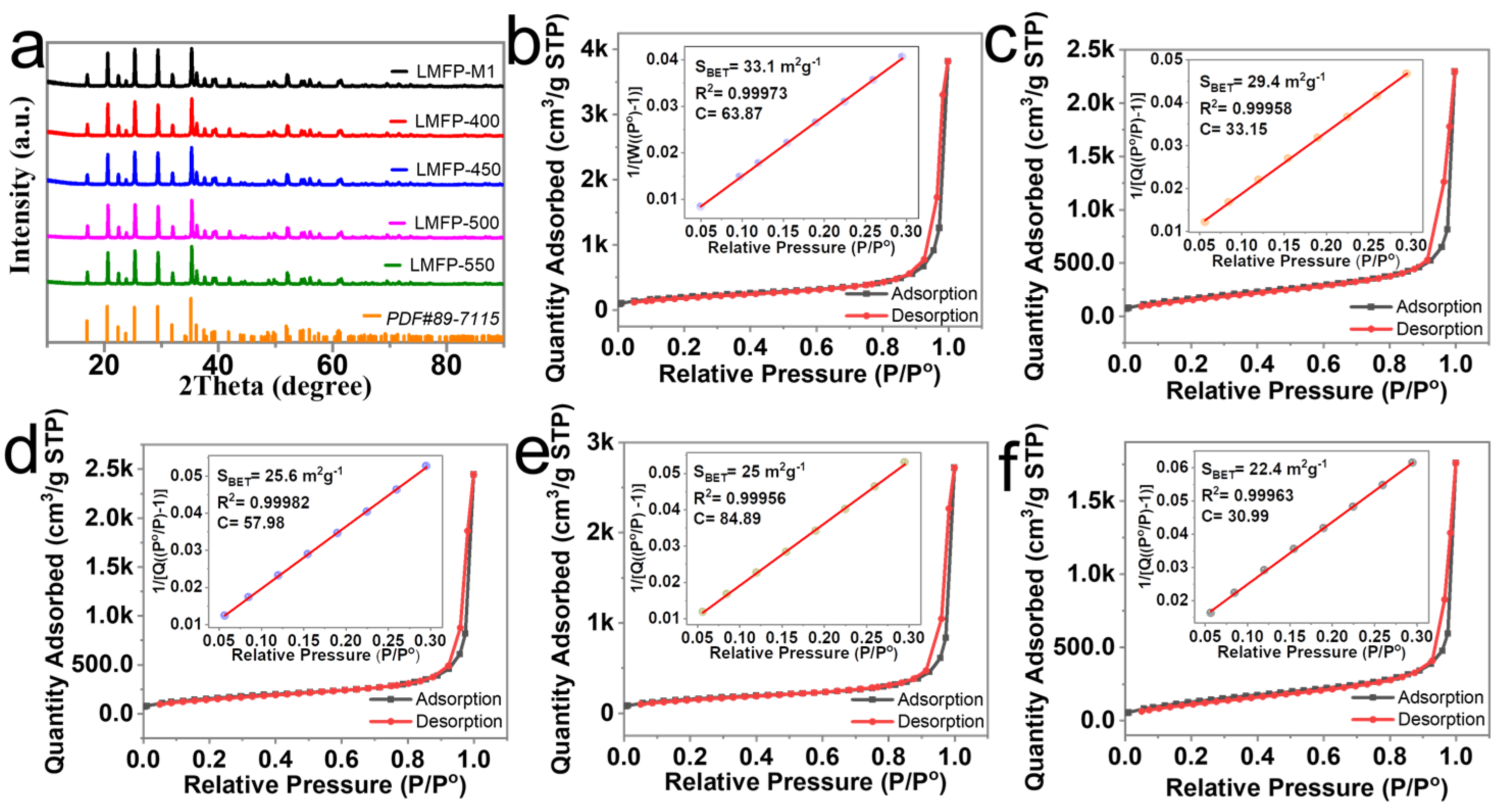
Figure 2. (a) XRD patterns and (bf) Specific surface area of LMFP-M1 and LMFP-400, LMFP-450, LMFP-500, LMFP-550.
Batteries 10 00114 g002
Figure 3. XPS images of LMFP-M1 (a,b), LMFP-500 (c,d).
Batteries 10 00114 g003
Figure 4. SEM images of LMFP-M1 (a), LMFP-400, LMFP-450, LMFP-500 and LMFP-550 (be); (f) EDS mapping of (g) Fe, (h) Co, and (i) Mn elements in LMFP-500 particle.
Batteries 10 00114 g004
Figure 5. TEM images of LMFP-M1 (a,b) and LMFP-400 (c,d), LMFP-450 (e,f), LMFP-500 (g,h,k,l), LMFP-550 (i,j).
Batteries 10 00114 g005
Figure 6. (a) Rate performance of LMFP-M1/C. (b) C-rate, (c) cathode material energy densities and (d) cycling performance of LMFP-M1/C and LMFP-400/C, LMFP-450/C, LMFP-500/C, LMFP-550/C. (e) C-rate and (f) cycling performance of LMFP-500/C pouch cell.
Batteries 10 00114 g006
Figure 7. (a) CV curves and (b) fitted Nyquist plots of LMFP-M1/C and LMFP-400/C, LMFP-450/C, LMFP-500/C, LMFP-550/C.
Batteries 10 00114 g007
Table 1. The specific surface area of LMFP-M1 and LMFP-400, LMFP-450, LMFP-500, LMFP-550 samples, and the compaction density and discharge median voltage of the above samples after carbon coating.
SamplesLMFP-M1LMFP-400LMFP-450LMFP-500LMFP-550
Specific surface area (m2/g)33.129.425.625.022.4
After carbon coatingLMFP-M1/CLMFP-400/CLMFP-450/CLMFP-500/CLMFP-550/C
Compaction density (g/cm³)1.962.182.272.342.43
Median Voltage (V)0.1 C4.0284.0253.9964.0093.995
0.2 C4.0073.9833.8763.9193.823
1 C3.8313.6953.5343.5233.486
2 C3.5183.4693.3793.3613.330
5 C3.2903.1853.1233.0693.074
10 C3.0092.7712.7542.6602.712
Disclaimer/Publisher’s Note: The statements, opinions and data contained in all publications are solely those of the individual author(s) and contributor(s) and not of MDPI and/or the editor(s). MDPI and/or the editor(s) disclaim responsibility for any injury to people or property resulting from any ideas, methods, instructions or products referred to in the content.

