Article

Constructing a LiPON Layer on a 3D Lithium Metal Anode as an Artificial Solid Electrolyte Interphase with Long-Term Stability

International School of Materials Science and Engineering, Wuhan University of Technology, Wuhan 430070, China
*
Authors to whom correspondence should be addressed.
These authors contributed equally to this work.
Batteries 2024, 10(1), 30; https://doi.org/10.3390/batteries10010030
Submission received: 15 December 2023 / Revised: 12 January 2024 / Accepted: 16 January 2024 / Published: 17 January 2024

Abstract

:
The problem of lithium dendrite growth has persistently hindered the advancement of lithium metal batteries. Lithium phosphorus oxynitride (LiPON), functioning as an amorphous solid electrolyte, is extensively employed as an artificial solid electrolyte interphase (SEI) owing to its remarkable stability and mechanical strength, which is beneficial for effectively mitigating dendrite growth. Nevertheless, the significant challenge arises from the volume changes in the Li metal anode during cycling, leading to the vulnerability of LiPON due to its high rigidity, which impedes the widespread use of LiPON. To address this problem, our study introduces a lithium-boron (Li-B) alloy as the anode, featuring a 3D structure, which can be synergistic with the artificial LiPON layer during cycling, leading to a better performance. The average Coulombic efficiency (CE) of a Li || Cu half-cell reaches 95% over 120 cycles. The symmetric cells exhibit sustained operation for 950 h with a low voltage polarization of less than 20 mV under a current density of 0.5 mA/cm2 and for 410 h under 1 mA/cm2.

1. Introduction

With the rapidly increasing demand for high-quality energy for electric vehicles and smart grids, lithium-ion batteries (LIBs) face the intrinsic challenge of low energy density. Lithium metal, hailed as the “holy grail” of batteries, stands out as the optimal choice for anode materials due to its exceptionally high theoretical specific capacity (3860 mAh/g or 2061 mAh/cm3), light weight (0.534 g/cm3), and lowest electrochemical potential (−3.04 V vs. the standard hydrogen electrode) [1,2,3,4,5,6]. However, the extreme reactivity of the Li metal leads to side effects, notably the production of the native solid electrolyte interphase (SEI). The native SEI lacks the stability needed during cycling, making it prone to breakdown and reconstruction in the process [7,8,9,10,11]. This results in an increasing SEI thickness, with electronically insulating materials covering the anode surface and deposited lithium falling off the electrode, forming the so-called “dead Li” and causing active lithium losses [12]. Furthermore, these fragile SEIs induce an inhomogeneous deposition of lithium, fostering the development of lithium dendrites. This dendritic growth leads to a decline in electrochemical performance and, in severe cases, penetration of the separator, resulting in battery failure [13,14,15,16,17,18].
To stabilize the Li metal anode, researchers have proposed developing artificial solid electrolyte interphases (SEIs) over several decades. An ideal artificial SEI should possess high ion conductivity, electronic insulation, and excellent mechanical properties [19,20,21,22,23]. Currently, artificial SEIs can be classified into two categories: organic and inorganic. The organic SEI layer, while flexible and ductile, enables close contact with lithium metal and accommodates volume changes [24,25,26,27,28,29,30]. However, most organic materials are unstable and prone to participating in side reactions, resulting in a complex composition for the organic SEI and making them difficult to regulate [22,31]. In contrast, inorganic artificial SEI exhibits better electrochemical stability and thermostability, leading to a growing inclination toward artificial SEI [32,33,34,35,36,37,38]. Lithium phosphorus oxynitride (LiPON) is an amorphous inorganic material widely used as a solid electrolyte and SEI due to its excellent stability with lithium metal, relatively high ion conductivity, and ability to homogenize the lithium ion flux [37,39,40,41,42,43,44]. Despite LiPON’s outstanding properties, its intrinsic brittleness limits its broad applications, as is true of other inorganic SEIs [45,46]. LiPON is too rigid to accommodate the volume change during cycling, leading to the development of cracks and fractures, where the electrolyte will come into contact with the anode directly and react uncontrollably; therefore, it is difficult for it to stay stable for cycling over a long time period [37,47]. A 3D host is a common solution utilized to address the issue of volume change in the lithium metal anode, as the rigid LiPON is supposed to better maintain the structural integrity and protect the anode during a long-term cycling process [48,49,50,51].
Herein, LiPON is fabricated on a LiB anode as an artificial SEI to synergistically improve the electrochemical performances of the lithium metal anode. Firstly, the LiB anode is composed of Li7B6 fibers and exists between the skeleton and free lithium metal, which can mitigate the volume changes in the anode during the lithium striping/plating processes. Secondly, as an artificial SEI, the LiPON layer can effectively protect the lithium metal from the undesirable side reactions with the electrolyte and homogenize lithium ion deposition to inhibit the irregular growth of the lithium metal. Lastly, the 3D structure in the LiB anode can support the rigid LiPON layer during the repeated charge/discharge process. With the mutually reinforcing effect, the composite anode demonstrates excellent electrochemical performance in both symmetric cells and full-cells. The symmetric cell sustains operation for 950 h with a relatively low polarization of less than 20 mV at 0.5 mA/cm2 for 0.5 mAh/cm2, as well as cycles of 410 h at 1 mA/cm2 for 1 mAh/cm2. Due to the well-conceived design, maintaining its structure and protecting the lithium metal anode for the long term, the full-cell exhibits outstanding capacity retention of 92.9% after 400 cycles at 0.5 C, with an average Coulombic efficiency of 99.84%.

2. Materials and Methods

2.1. Fabrication of the LiB@LiPON Electrode

RF magnetron sputtering was used as the deposition technique, and the whole device was embedded in an argon glove box (Mbraun, O2 < 0.1 ppm, H2O < 0.1 ppm) to prevent the materials from undergoing deterioration. A LiPON layer with a thickness of around 300 nm was synthesized with the Li3PO4 target (50.8 mm in diameter, bought from Zhongnuo New Materials Technology Co., Ltd., Beijing, China) on a LiB anode at room temperature (50 μm thick, bought from China Energy Lithium Co., Ltd., Tianjin, China). The initial vacuum of the chamber was below 3.0 × 10⁻⁴ Pa, the working pressure was set at 0.5 Pa, and the chamber was filled with pure nitrogen gas. The distance between the target and the substrate was 10 cm, and a LiPON layer with a thickness of around 300 nm was obtained under the RF power of 50 W for 3 h. The as-prepared sample was denoted as LiB@LiPON.

2.2. Materials Characterization

Scanning electron microscopy (SEM, JEOL JSM-7100 F, JEOL Ltd., Tokyo, Japan) and energy dispersive X-ray spectroscopy (EDS) data were used to study the morphologies of the samples. X-ray photoelectron spectroscopy (XPS, AXIS SUPRA, Shimadzu Group Co., Kyoto, Japan) using a VG MultiLab 2000 instrument (Thermo Fisher Scientific, Waltham, MA, USA) was applied to detect the different valence states of the elements. All the sample preparation processes were operated using a glove box (Vigor, O2 < 0.1 ppm, H2O < 0.1 ppm) to protect the sample from oxidation and hydrolysis.

2.3. Electrochemical Measurements

The electrochemical tests were all conducted using CR2016-type coin cells, assembled in the argon glove box. For Coulombic efficiency (CE) tests, Cu foil was used as the cathode (10 mm in diameter), while the anode was punched into 14 mm disc in diameter. A Celgard 2500 membrane was punched into 17 mm disc in diameter and used as the separator, and the electrolyte was composed of 1 M lithium bis(trifluoromethane)sulfonimide (LiTFSI) in DME/DOL (v:v = 1:1) with 1 wt% lithium nitrate (LiNO3). Next, a 30 μL electrolyte was added to each side of the coin cells. The cells were first set to discharge for 1 h at the current density of 1 mA/cm2 and charge up to 1 V at 1 mA/cm2, and then they were repeatedly cycled with the same conditions. Symmetrical cells were assembled with cathodes and anodes of the same materials, and the separator and electrolyte were the same as in the CE tests. A high-mass-loading LiFePO4 (LFP, 18.3 mg/cm2, bought from Shenzhen Hongchuang Technology Co., Ltd., Shenzhen, China) was used as the cathode material in the full-cell tests, and the separator and electrolyte were kept the same. All the coin cells were tested using a Land system. Electrochemical impedance spectroscopy (EIS) measurements were carried out using an EC-lab workstation over a frequency ranging from 100 mHz to 100 kHz, with an amplitude of 10 mV.

3. Results and Discussion

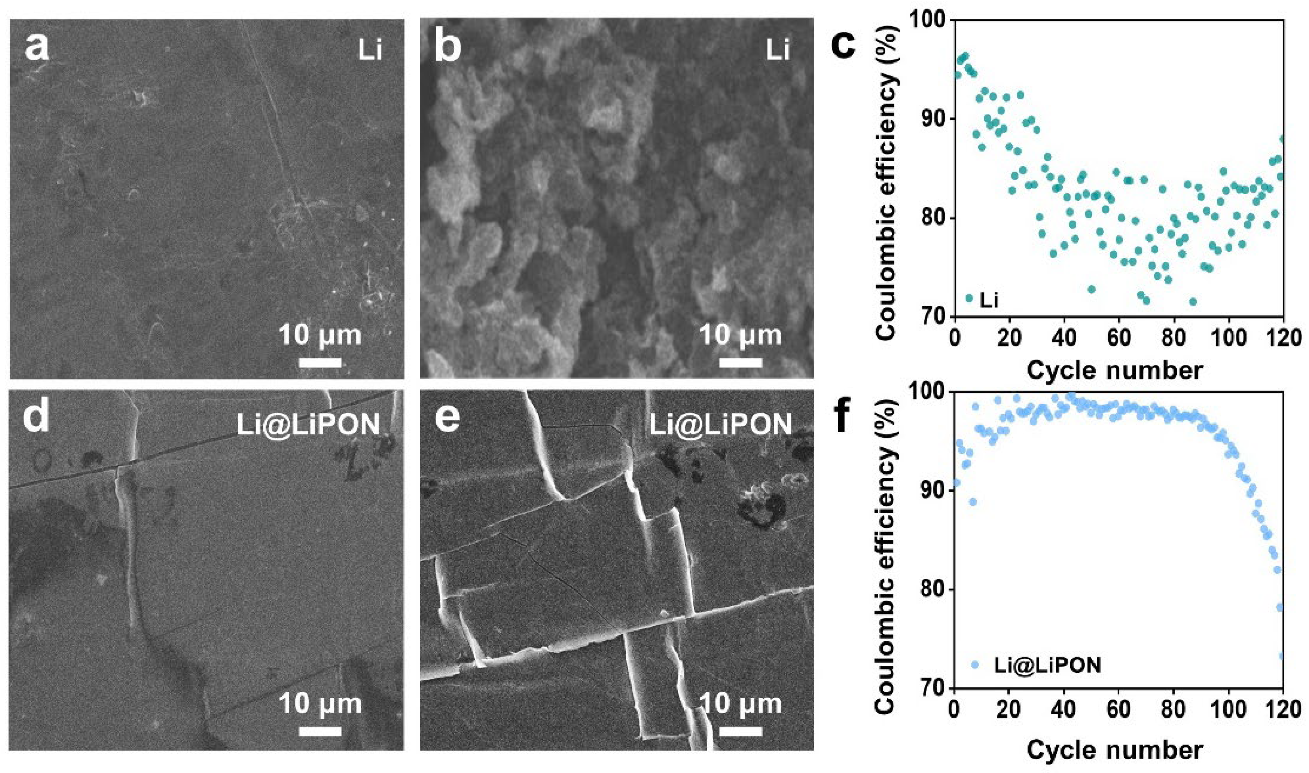
3.1. Morphology Revolution of LiPON on Pure Lithium Metal

In order to verify the effect of the LiPON modification on a pure lithium metal anode, Li || Cu half-cells were assembled to conduct CE tests, and the corresponding results are shown in Figure 1. Figure 1a,b show the SEM images of the pure lithium metal anode before and after cycling, respectively. After cycling, it is obvious that there are substantial lithium dendrites of irregular growth on the surface. The Coulombic efficiency of a pure lithium metal anode without protection was unstable during the whole cycling process (Figure 1c). A dense LiPON layer was fabricated on the lithium metal anode via RF magnetron sputtering (Figure 1d), which is noted as Li@LiPON. It can be observed that there were some cracks on the LiPON layer due to the high surface tension of lithium. After cycling, the cracks became more obvious, which was caused by the repeated volume change in the lithium metal anode. The cracks allowed direct contact between the anode and the electrolyte to cause the side reactions. The modified anode initially exhibited a higher Coulombic efficiency. However, a sudden decrease could be found after around 90 cycles, which can be explained by the destruction of the structural integrity of the LiPON layer after a period of cycling.

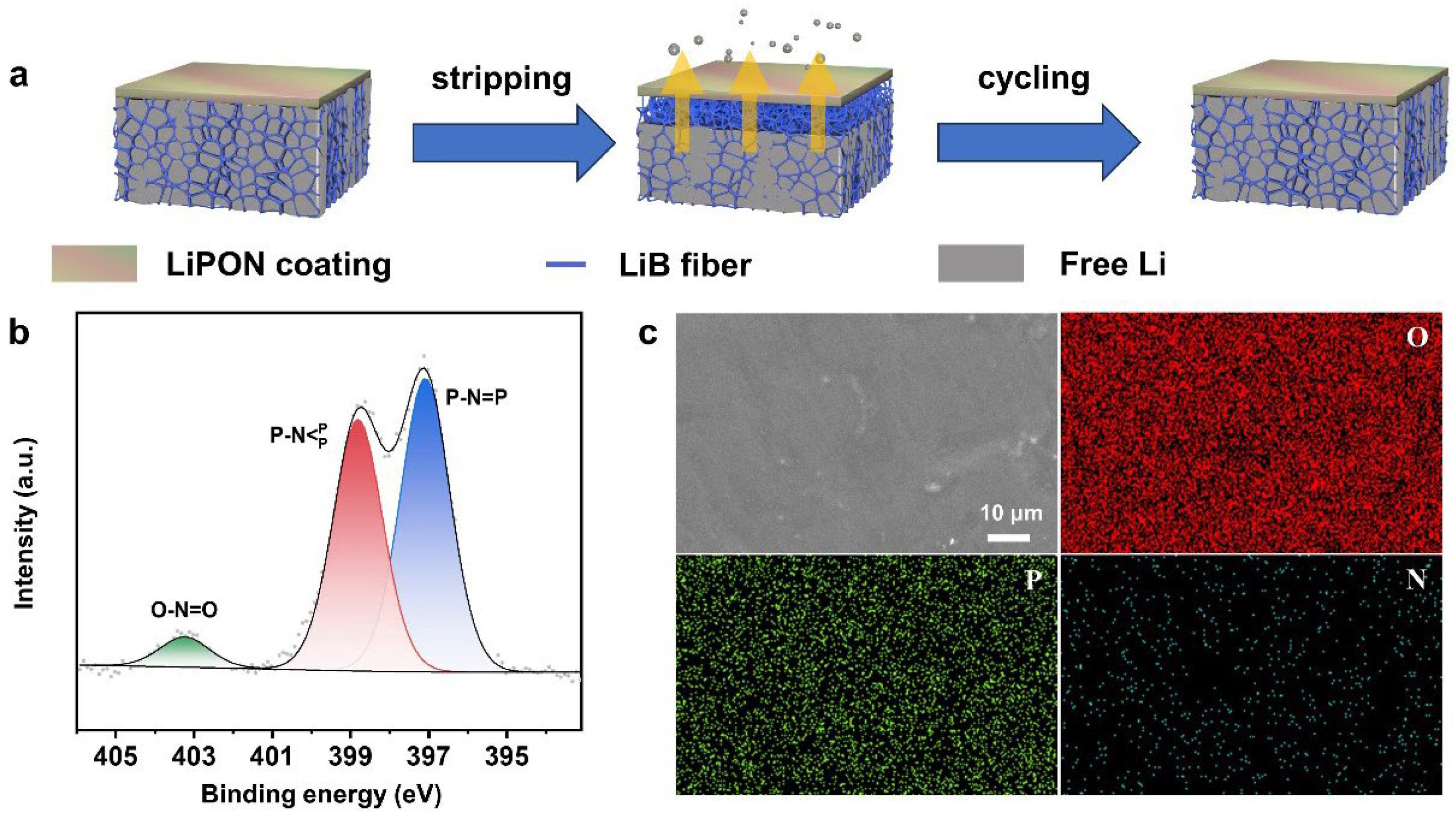
3.2. Characterizations of LiPON on LiB

Figure 2 illustrates the fundamental information about this experiment. Figure 2a presents a schematic illustration of the structure of the LiB anode modified by the LiPON layer, as well as the overall evolution of the anode’s surface during continuous cycling, which is supposed to maintain the structural integrity over long-term cycling. LiB has a unique two-phase system involving Li7B6 fibers embedded with free lithium metal, whose structure can effectively mitigate the volume change in the lithium metal during cycling. The density of LiB is 0.83 g/cm3, and the mass of the LiB electrode with a diameter of 14 mm is 0.0064 g. After the sputtering of LiPON, the mass of the as-prepared LiB@LiPON anode has no obvious increase because the LiPON layer is too thin. In order to identify the charge characteristic of LiB anode, a LiB || Li cell was assembled and charged to 1 V at 0.2 mA/cm2, and the charge curve is shown in Figure S1. There are three obvious voltage plateaus. The first one is below 0.1 V vs. Li+/Li, representing the stripping of free Li and providing a capacity of about 2170 mAh/g. The other two are around 0.68 V and 0.8 V vs. Li+/Li, corresponding to the electrochemical stripping of Li from the LiB skeleton, and this process contributes to the capacity of about 660 mAh/g. The overall capacity is 2830 mAh/g, which constitutes a lithium content of 73%, of which the free Li content is 56%. The charge curve of the LiB anode is well matched with the previous research [52]. Figure S2 provides optical images of LiB (left) and LiB@LiPON (right). It can be seen that the LiPON layer is evenly coated on the LiB surface. To determine the most suitable thickness of the LiPON layer, various sputtering times were investigated. As depicted in Figure S3, the results indicate that the samples subjected to 1 h of sputtering and 2 h of sputtering are mostly broken, primarily due to the insufficient thickness of the LiPON layer, rendering it unable to withstand the stress. However, for sputtering durations exceeding 3 h, the LiPON layers remain in good condition. The electrochemical impedance spectroscopy (EIS) profiles shown in Figure S4 illustrate that impedance increases with the extension of the sputtering time, correlating with the increased thickness of the LiPON coating. The x-intercept in the high-frequency region represents the solution resistance (Rs), while the diameter of the semi-circle at a high frequency corresponds to the solid electrolyte interphase resistance (RSEI), and the one at a low frequency can be attributed to the charge-transfer resistance (Rct) [44]. The RSEI values of these four samples are 117 Ω, 142 Ω, 170 Ω, and 246 Ω, respectively. Consequently, the 3 h sputtering sample is selected as the primary specimen, as it has both structural integrity and a low impedance.
On account of LiPON being an amorphous material, XRD is unavailable to test its existence. The bonding valence state of nitrogen in the sample is investigated using X-ray photoelectron spectroscopy (XPS), confirming the successful formation of LiPON. As depicted in Figure 2b, the peaks at 398.9 eV and 396.8 eV correspond to the triply coordinated state and the doubly coordinated state, respectively. Furthermore, the peak at 403.2 eV is attributed to O-N=O [43,53]. Figure 2c provides a top-view SEM image and the corresponding elemental mapping images of LiB@LiPON, which further affirm the existence of LiPON and demonstrate a smooth surface with homogeneous elemental distributions of P, O, and N. It is evident that the LiPON layer is complete and uniform after 3 h of sputtering. And in Figure S5, it can be seen that the thickness of the sample suggests a sputtering rate of approximately 100 nm/h under such experimental conditions.

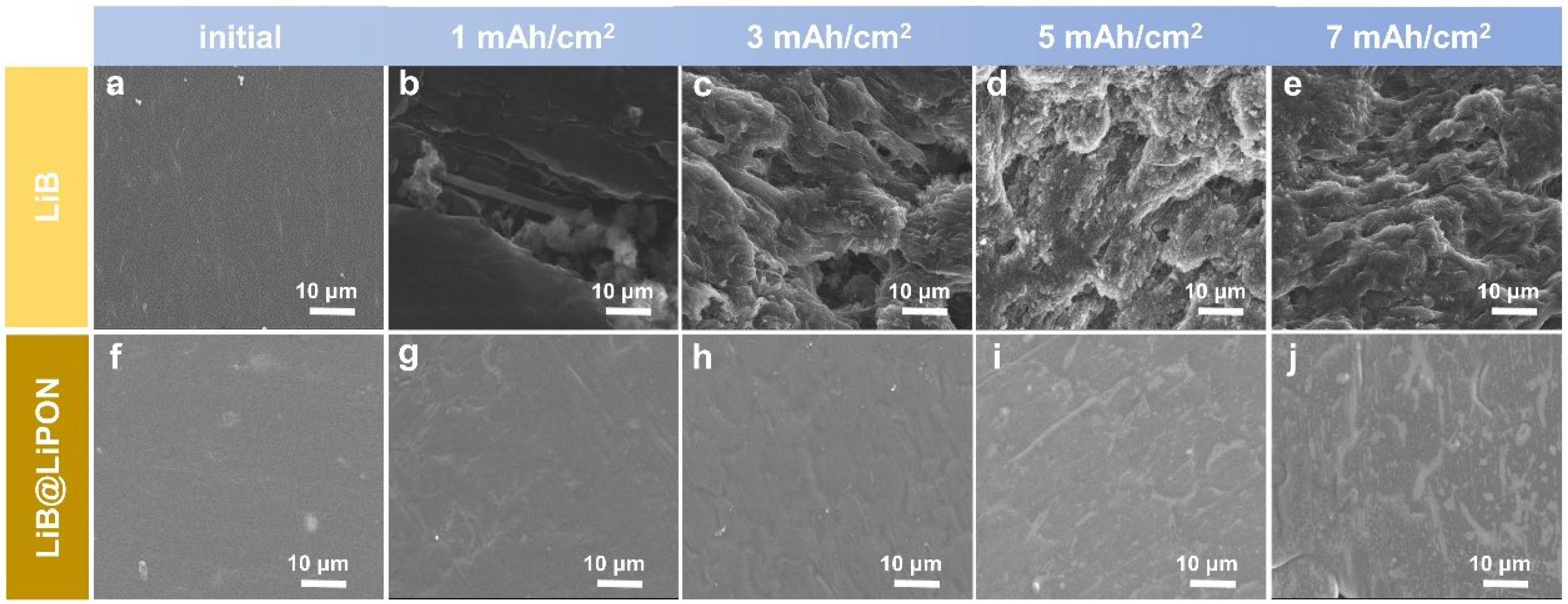
3.3. Morphology Revolution of LiB@LiPON during the First Charge Process

To observe the variation in the LiPON layer during cycling, the characteristics of lithium stripping of the LiB anode in the first charge process are studied. Figure 3 presents SEM images that illustrate the morphology of the anode after stripping different capacities of lithium. It can be seen that the surface of the pure LiB anode is smooth at first (Figure 3a). After stripping 1 mAh/cm2 of lithium, it is observed that the 3D skeleton of the Li7B6 fiber is partially exposed, resulting in a bumpy surface due to the removal of free lithium from the 3D structure (Figure 3b). With an increase in the stripping depth, more Li7B6 fibers appear (Figure 3c–e). However, this process does not destroy the 3D structure of the LiB anode, indicating the maintenance of its support function. Figure 3f–j represent the LiB@LiPON anode at different stages of lithium stripping, ranging from 0 to 7 mAh/cm2, respectively. Despite the presence of minor grooves on the LiPON layer, SEM images demonstrate that the LiB@LiPON anode maintains a complete surface even after 7 mAh/cm2 lithium stripping, indicating its excellent potential stability. These results are attributed to the support of the 3D skeleton of the LiB anode.

3.4. Electrochemical Performance of the LiB@LiPON Anode

To demonstrate the beneficial impact of LiPON on battery performance, CE tests and symmetrical cell tests are conducted. The enhancement in the CE of LiB@LiPON is evident from Figure 4a,d. The CE of LiB || Cu is relatively high after the first 30 cycles and then turns to be unstable in subsequent cycles, while the average CE of LiB@LiPON || Cu still stays stable and maintains over 95% after cycling 120 times. This significant improvement is attributed to the wider electrochemical window and the greater stability of LiPON compared to the native SEI during cycling in electrochemical behavior. The symmetrical cells, namely LiB || LiB and LiB@LiPON || LiB@LiPON, are assembled and tested under the current densities and capacities of 0.5 mA/cm2–0.5 mAh/cm2 and 1 mA/cm2–1 mAh/cm2. The corresponding results are illustrated in Figure 4b and Figure 4e, respectively. Under the experimental condition of 0.5 mA/cm2–0.5 mAh/cm2, LiB@LiPON || LiB@LiPON cycles for 950 h, while the pure LiB cycles for only 210 h, and under 1 mA/cm2–1 mAh/cm2, LiB@LiPON || LiB@LiPON gives a result of 410 h, while the pure LiB cycles for only 130 h. As the cycling process continues, the overpotential of LiB@LiPON || LiB@LiPON cells gradually decreases and tends to be stable at a relatively small polarization. These findings indicate that, under different current densities, LiB coated with a LiPON layer can cycle for a longer duration than its uncoated counterpart, maintaining integrity throughout the cycling process. The SEM images of the top view of LiB and LiB@LiPON electrodes after 300 cycles, as shown in Figure 4c,f, demonstrate that the surface of LiB@LiPON remains smooth, with only minor cracks, which explains why LiB@LiPON shows an improved electrochemical performance. This observation demonstrates the stability of the LiPON coating on the Li-B alloy.

3.5. Characterizations of the LiB@LiPON Anode after Cycling

To verify the stability of the LiB@LiPON, XPS analysis is conducted to determine the composition of the SEI layer after cycling, and the results are presented in Figure 5. The spectra in Figure 5a–c correspond to the wide spectrum, N 1s, and F 1s of the LiB anode after cycling, respectively. It is evident that the fluorine content is relatively high, which is attributed to native SEI formed by the reaction between the Li metal and the electrolyte. The unstable native SEI leads to the subsequent degradation of the performance. In contrast, Figure 5d–f depict the corresponding spectra of the LiB@LiPON anode. On one hand, the figure show an almost fluorine-free composition, referring to the effective separation of anode and electrolyte. On the other hand, N 1s has little variation after cycling, indicating that the composition and structure of LiPON remain almost the same as before. Figure S6a is the cross-section view of the SEM images of the cycled LiB@LiPON anode, with the distribution of corresponding elements N, O, and P shown in Figure S6b–S6d, respectively. Figure S7a gives a top view of an SEM image of the cycled LiB@LiPON anode, with the distribution of the corresponding elements N, O, and P shown in Figure S7b–S7d, respectively. These results show a complete layer, illustrating its homogeneity and integrity after cycling.

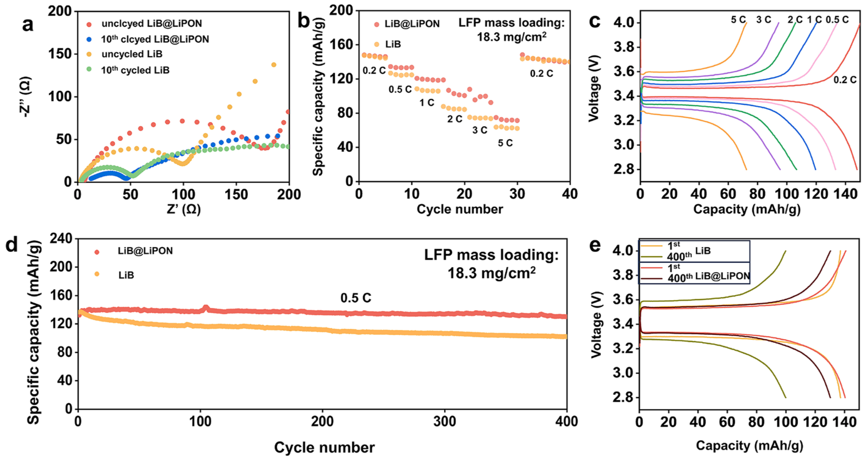
3.6. Electrochemical Performances of the Full-Cells with the LiB@LiPON Anode

To further confirm the stability of the LiB@LiPON electrode, additional electrochemical tests, electrochemical impedance spectroscopy (EIS) of symmetric batteries, and full batteries are conducted. Figure 6a presents the enlarged EIS results for LiB || LiB and LiB@LiPON || LiB@LiPON cells before cycling and after 10 cycles at a current density of 0.5 mA/cm2. Additionally, Figure S8a provides the overall plots. Although the initial impedance value of LiB@LiPON is a little higher than that of pure LiB, attributed to the LiPON coating, after 10 cycles, the value of RSEI of LiB@LiPON decreases to a level similar to that of the LiB. This suggests that LiB@LiPON exhibits better contact and stability than LiB. Figure S8b illustrates the equivalent circuit model used for fitting the impedance. To further clarify the superior performance of LiB@LiPON compared to pure LiB, full-cell tests assessing long-cycle and rate performance paired with high-loading LiFePO4 (18.3 mg/cm2) are conducted. The results indicate that LiB@LiPON outperforms pure LiB. Figure 6b illustrates the rate performance of batteries with different anodes, showing that LiB@LiPON || LFP exhibits higher discharge capacities (148, 134, 121, 107, 100, and 75 mAh/g) at 0.2, 0.5, 1, 2, 3, and 5 C, respectively. Additionally, the discharge capacity recovers to 148 mAh/g when the current rate returns to 0.2 C, indicating a superior rate performance compared to LiB || LFP. Figure 6c depicts the charge–discharge curve of the rate performance of LiB@LiPON || LFP, which is better than that of the pure LiB shown in Figure S9, attributed to the high stability of LiPON, which helps it to avoid the repeated reactions between the anode and electrolyte. Figure 6d shows the long-term cycling performance of LiB@LiPON || LFP at 0.5 C. LiB@LiPON || LFP maintains a discharge capacity of 130 mAh/g, corresponding to a 92.9% capacity retention, and a high average Coulombic efficiency of 99.84% after 400 cycles, while LiB || LFP only retains a discharge capacity of 102 mAh/g, which means that it has a capacity retention of only 73.9%. Some electrochemical performances in other work are listed in Table S1, and our work shows a relatively good performance. Figure 6e presents the charge–discharge curve of LiB || LFP and LiB@LiPON || LFP at 0.5 C for the 1st and 400th cycles, respectively. The change in the polarization of LiB@LiPON is smaller than pure LiB, which also illustrates that LiB@LiPON has a better stability. Figure S10a–c are the images of LiB anode before cycling and after the 1st and 100th cycles, respectively. In contrast, the SEM images of the LiB@LiPON anode shown in Figure S10d–f prove that LiPON effectively regulates lithium-ion deposition.

4. Conclusions

In summary, a facile RF magnetron sputtering method was employed to fabricate a dense and stable LiPON layer, serving as an SEI, on the LiB alloy. This approach can not only effectively address the rigidity issue associated with LiPON but also improve the positive effect of LiPON as an artificial SEI layer. In contrast to the pure Li metal, LiB possesses a unique 3D structure that is capable of accommodating the volume change during cycling and providing support for the protective layer, preventing LiPON from disintegration. As a consequence, the LiPON coating on the LiB anode exhibits a greater stability than that on the pure Li metal after cycling, facilitating a homogeneous Li-ion flux. The achieved average CE reaches 95% over 120 cycles in half-cells, and the symmetric cell exhibits a long lifespan of 950 h with a relatively low polarization of less than 20 mV at 0.5 mA/cm2 for 0.5 mAh/cm2 and cycles for 410 h at 1 mA/cm2 for 1 mAh/cm2. When coupled with a high loading of the LiFePO4 (18.3 mg/cm2), an outstanding capacity retention of 92.9% is achieved after 400 cycles at a rate of 0.5 C. This work introduces a facile method for fabricating an artificial SEI, and the improved performances of LiB@LiPON anode illustrate that the concept of leveraging the synergies between a 3D host and an artificial SEI layer holds promise for future advancements in anode protection.

Supplementary Materials

The following supporting information can be downloaded via this link: https://www.mdpi.com/article/10.3390/batteries10010030/s1; Figure S1 Charge curve of the LiB anode. Figure S2: Optical pictures of LiB (left) and LiB@LiPON (right) anodes. Figure S3: (a–d) SEM images of LiB@LiPON anode of 1 h sputtering, 2 h sputtering, 3 h sputtering, and 4 h sputtering, respectively. Figure S4: (a–d) EIS profiles of LiB@LiPON || LiB@LiPON symmetric batteries with 1 h sputtering, 2 h sputtering, 3 h sputtering, and 4 h sputtering samples, respectively. Figure S5: Cross-section view of LiB@LiPON anode before cycling. Figure S6: (a) Cross-section view of LiB@LiPON anode after cycling; (b–d) SEM elemental mapping images of the corresponding elemental mapping images of N, O, and P. Figure S7: (a) Top view of the cycled LiB@LiPON anode; (b–d) SEM elemental mapping images of Figure S7a. Figure S8: (a) Enlarged view of the high-frequency area of the EIS profile; (b) equivalent circuit model for fitting the impedance. Figure S9: Charge–discharge curves of LiB || LFP at different current densities. Figure S10: (a) SEM image of LiB anode before cycling; (b,c) SEM images of LiB anode after 1st and 100th cycles, respectively; (d) SEM image of LiB@LiPON anode before cycling; (e,f) SEM images of LiB@LiPON anode after 1st and 100th cycles, respectively. Table S1: Some other work about electrochemical performance when using LiPON as an interface. References [54,55,56,57,58] are cited in the Supplementary Materials.

Author Contributions

K.Y. and X.X.: Writing—Reviewing and Editing and Supervision. Q.P. and Y.Y.: Writing original draft preparation. C.S.: Visualization. Y.Z. and M.G.: Formal analysis. All authors discussed the results and commented on the manuscript. All authors have read and agreed to the published version of the manuscript.

Funding

This work was supported by the Hubei Provincial Natural Science Foundation of China (2022CFB355) and the National Innovation and Entrepreneurship Training Program for College Students (No. S202310497018).

Data Availability Statement

The data that support the findings of this study are available from the corresponding author upon reasonable request.

Conflicts of Interest

The authors declare no conflicts of interest.

References

  1. Liu, J.; Bao, Z.; Cui, Y.; Dufek, E.J.; Goodenough, J.B.; Khalifah, P.; Li, Q.; Liaw, B.Y.; Liu, P.; Manthiram, A.; et al. Pathways for practical high-energy long-cycling lithium metal batteries. Nat. Energy 2019, 4, 180–186. [Google Scholar] [CrossRef]
  2. Hu, M.; Tong, Z.; Cui, C.; Zhai, T.; Li, H. Facile, Atom-Economic, Chemical Thinning Strategy for Ultrathin Lithium Foils. Nano Lett. 2022, 22, 3047–3053. [Google Scholar] [CrossRef] [PubMed]
  3. Cheng, X.B.; Zhang, R.; Zhao, C.Z.; Zhang, Q. Toward Safe Lithium Metal Anode in Rechargeable Batteries: A Review. Chem. Rev. 2017, 117, 10403–10473. [Google Scholar] [CrossRef]
  4. Niu, C.; Pan, H.; Xu, W.; Xiao, J.; Zhang, J.G.; Luo, L.; Wang, C.; Mei, D.; Meng, J.; Wang, X.; et al. Self-smoothing anode for achieving high-energy lithium metal batteries under realistic conditions. Nat. Nanotechnol. 2019, 14, 594–601. [Google Scholar] [CrossRef] [PubMed]
  5. Yan, J.; Huang, H.; Tong, J.; Li, W.; Liu, X.; Zhang, H.; Huang, H.; Zhou, W. Recent progress on the modification of high nickel content NCM: Coating, doping, and single crystallization. Interdiscip. Mater. 2022, 1, 330–353. [Google Scholar] [CrossRef]
  6. Huang, Y. The discovery of cathode materials for lithium-ion batteries from the view of interdisciplinarity. Interdiscip. Mater. 2022, 1, 323–329. [Google Scholar] [CrossRef]
  7. Kim, M.S.; Ryu, J.-H.; Deepika; Lim, Y.R.; Nah, I.W.; Lee, K.-R.; Archer, L.A.; Il Cho, W. Langmuir–Blodgett artificial solid-electrolyte interphases for practical lithium metal batteries. Nat. Energy 2018, 3, 889–898. [Google Scholar] [CrossRef]
  8. Cha, E.; Lee, H.; Choi, W. Improving Lithium-Metal Battery Performance under the Conditions of Lean Electrolyte through MoS2 Coating. ChemElectroChem 2020, 7, 890–892. [Google Scholar] [CrossRef]
  9. Shen, X.; Cheng, X.; Shi, P.; Huang, J.; Zhang, X.; Yan, C.; Li, T.; Zhang, Q. Lithium–matrix composite anode protected by a solid electrolyte layer for stable lithium metal batteries. J. Energy Chem. 2019, 37, 29–34. [Google Scholar] [CrossRef]
  10. Ghazi, Z.A.; Sun, Z.; Sun, C.; Qi, F.; An, B.; Li, F.; Cheng, H.M. Key Aspects of Lithium Metal Anodes for Lithium Metal Batteries. Small 2019, 15, e1900687. [Google Scholar] [CrossRef]
  11. Zhang, T.; Lu, H.; Yang, J.; Xu, Z.; Wang, J.; Hirano, S.I.; Guo, Y.; Liang, C. Stable Lithium Metal Anode Enabled by a Lithiophilic and Electron/Ion Conductive Framework. ACS Nano 2020, 14, 5618–5627. [Google Scholar] [CrossRef]
  12. Adhitama, E.; Bela, M.M.; Demelash, F.; Stan, M.C.; Winter, M.; Gomez-Martin, A.; Placke, T. On the Practical Applicability of the Li Metal-Based Thermal Evaporation Prelithiation Technique on Si Anodes for Lithium Ion Batteries. Adv. Energy Mater. 2023, 13, 2203256. [Google Scholar] [CrossRef]
  13. Ko, J.; Yoon, Y.S. Lithium fluoride layer formed by thermal evaporation for stable lithium metal anode in rechargeable batteries. Thin Solid Film. 2019, 673, 119–125. [Google Scholar] [CrossRef]
  14. Zhang, J.; Shi, J.; Wen, X.; Zhao, Y.; Guo, J. Properties of Thin Lithium Metal Electrodes in Carbonate Electrolytes with Realistic Parameters. ACS Appl. Mater. Interfaces 2020, 12, 32863–32870. [Google Scholar] [CrossRef] [PubMed]
  15. Zhang, D.; Dai, A.; Fan, B.; Li, Y.; Shen, K.; Xiao, T.; Hou, G.; Cao, H.; Tao, X.; Tang, Y. Three-Dimensional Ordered Macro/Mesoporous Cu/Zn as a Lithiophilic Current Collector for Dendrite-Free Lithium Metal Anode. ACS Appl. Mater. Interfaces 2020, 12, 31542–31551. [Google Scholar] [CrossRef] [PubMed]
  16. Ma, J.; Yang, J.; Wu, C.; Huang, M.; Zhu, J.; Zeng, W.; Li, L.; Li, P.; Zhao, X.; Qiao, F.; et al. Stabilizing nucleation seeds in Li metal anode via ion-selective graphene oxide interfaces. Energy Storage Mater. 2023, 56, 572–581. [Google Scholar] [CrossRef]
  17. Guo, J.C.; Tan, S.J.; Zhang, C.H.; Wang, W.P.; Zhao, Y.; Wang, F.; Zhang, X.S.; Wen, R.; Zhang, Y.; Fan, M.; et al. A Self-Reconfigured, Dual-Layered Artificial Interphase Toward High-Current-Density Quasi-Solid-State Lithium Metal Batteries. Adv. Mater. 2023, 35, e2300350. [Google Scholar] [CrossRef]
  18. Kolesnikov, A.; Kolek, M.; Dohmann, J.F.; Horsthemke, F.; Börner, M.; Bieker, P.; Winter, M.; Stan, M.C. Galvanic Corrosion of Lithium-Powder-Based Electrodes. Adv. Energy Mater. 2020, 10, 2000017. [Google Scholar] [CrossRef]
  19. Qian, S.; Chen, H.; Zheng, M.; Zhu, Y.; Xing, C.; Tian, Y.; Yang, P.; Wu, Z.; Zhang, S. Complementary combination of lithium protection strategies for robust and longevous lithium metal batteries. Energy Storage Mater. 2023, 57, 229–248. [Google Scholar] [CrossRef]
  20. Hou, L.P.; Yao, N.; Xie, J.; Shi, P.; Sun, S.Y.; Jin, C.B.; Chen, C.M.; Liu, Q.B.; Li, B.Q.; Zhang, X.Q.; et al. Modification of Nitrate Ion Enables Stable Solid Electrolyte Interphase in Lithium Metal Batteries. Angew. Chem. Int. Ed. Engl. 2022, 61, e202201406. [Google Scholar] [CrossRef]
  21. Chang, C.; Yao, Y.; Li, R.; Guo, Z.H.; Li, L.; Pan, C.; Hu, W.; Pu, X. Self-healing single-ion-conductive artificial polymeric solid electrolyte interphases for stable lithium metal anodes. Nano Energy 2022, 93, 106871. [Google Scholar] [CrossRef]
  22. Chang, S.; Jin, X.; He, Q.; Liu, T.; Fang, J.; Shen, Z.; Li, Z.; Zhang, S.; Dahbi, M.; Alami, J.; et al. In Situ Formation of Polycyclic Aromatic Hydrocarbons as an Artificial Hybrid Layer for Lithium Metal Anodes. Nano Lett. 2022, 22, 263–270. [Google Scholar] [CrossRef]
  23. Zhao, Q.; Stalin, S.; Archer, L.A. Stabilizing metal battery anodes through the design of solid electrolyte interphases. Joule 2021, 5, 1119–1142. [Google Scholar] [CrossRef]
  24. Huang, Z.; Lai, J.-C.; Liao, S.-L.; Yu, Z.; Chen, Y.; Yu, W.; Gong, H.; Gao, X.; Yang, Y.; Qin, J.; et al. A salt-philic, solvent-phobic interfacial coating design for lithium metal electrodes. Nat. Energy 2023, 8, 577–585. [Google Scholar] [CrossRef]
  25. Lu, Q.; He, Y.B.; Yu, Q.; Li, B.; Kaneti, Y.V.; Yao, Y.; Kang, F.; Yang, Q.H. Dendrite-Free, High-Rate, Long-Life Lithium Metal Batteries with a 3D Cross-Linked Network Polymer Electrolyte. Adv. Mater. 2017, 29, 1604460. [Google Scholar] [CrossRef]
  26. Wu, J.; Rao, Z.; Liu, X.; Shen, Y.; Fang, C.; Yuan, L.; Li, Z.; Zhang, W.; Xie, X.; Huang, Y. Polycationic Polymer Layer for Air-Stable and Dendrite-Free Li Metal Anodes in Carbonate Electrolytes. Adv. Mater. 2021, 33, e2007428. [Google Scholar] [CrossRef]
  27. Zhu, B.; Jin, Y.; Hu, X.; Zheng, Q.; Zhang, S.; Wang, Q.; Zhu, J. Poly(dimethylsiloxane) Thin Film as a Stable Interfacial Layer for High-Performance Lithium-Metal Battery Anodes. Adv. Mater. 2017, 29, 1603755. [Google Scholar] [CrossRef] [PubMed]
  28. Stalin, S.; Chen, P.; Li, G.; Deng, Y.; Rouse, Z.; Cheng, Y.; Zhang, Z.; Biswal, P.; Jin, S.; Baker, S.P.; et al. Ultrathin zwitterionic polymeric interphases for stable lithium metal anodes. Matter 2021, 4, 3753–3773. [Google Scholar] [CrossRef]
  29. Liu, L.; Jiang, H.; Hu, R.; Shen, Z.; Li, H.; Liu, J. Tough lithium-rich organic film via molecular layer deposition for highly stable lithium metal anode. J. Power Sources 2023, 555, 232395. [Google Scholar] [CrossRef]
  30. Wang, Q.; Yang, J.; Huang, X.; Zhai, Z.; Tang, J.; You, J.; Shi, C.; Li, W.; Dai, P.; Zheng, W.; et al. Rigid and Flexible SEI Layer Formed Over a Cross-Linked Polymer for Enhanced Ultrathin Li Metal Anode Performance. Adv. Energy Mater. 2022, 12, 2103972. [Google Scholar] [CrossRef]
  31. Kang, D.; Hart, N.; Koh, J.; Ma, L.; Liang, W.; Xu, J.; Sardar, S.; Lemmon, J.P. Rearrange SEI with artificial organic layer for stable lithium metal anode. Energy Storage Mater. 2020, 24, 618–625. [Google Scholar] [CrossRef]
  32. Huang, K.; Song, S.; Xue, Z.; Niu, X.; Peng, X.; Xiang, Y. In-situ formation of LiF-rich solid-electrolyte interphases on 3D lithiophilic skeleton for stable lithium metal anode. Energy Storage Mater. 2023, 55, 301–311. [Google Scholar] [CrossRef]
  33. Ma, X.-X.; Shen, X.; Chen, X.; Fu, Z.-H.; Yao, N.; Zhang, R.; Zhang, Q. The Origin of Fast Lithium-Ion Transport in the Inorganic Solid Electrolyte Interphase on Lithium Metal Anodes. Small Struct. 2022, 3, 2200071. [Google Scholar] [CrossRef]
  34. Zheng, Y.; Xia, S.; Dong, F.; Sun, H.; Pang, Y.; Yang, J.; Huang, Y.; Zheng, S. High Performance Li Metal Anode Enabled by Robust Covalent Triazine Framework-Based Protective Layer. Adv. Funct. Mater. 2021, 31, 2006159. [Google Scholar] [CrossRef]
  35. Niu, J.; Wang, M.; Cao, T.; Cheng, X.; Wu, R.; Liu, H.; Zhang, Y.; Liu, X. Li metal coated with Li3PO4 film via atomic layer deposition as battery anode. Ionics 2021, 27, 2445–2454. [Google Scholar] [CrossRef]
  36. Chen, H.; Pei, A.; Lin, D.; Xie, J.; Yang, A.; Xu, J.; Lin, K.; Wang, J.; Wang, H.; Shi, F.; et al. Uniform High Ionic Conducting Lithium Sulfide Protection Layer for Stable Lithium Metal Anode. Adv. Energy Mater. 2019, 9, 1900858. [Google Scholar] [CrossRef]
  37. Liu, W.; Guo, R.; Zhan, B.; Shi, B.; Li, Y.; Pei, H.; Wang, Y.; Shi, W.; Fu, Z.; Xie, J. Artificial Solid Electrolyte Interphase Layer for Lithium Metal Anode in High-Energy Lithium Secondary Pouch Cells. ACS Appl. Energy Mater. 2018, 1, 1674–1679. [Google Scholar] [CrossRef]
  38. Li, N.W.; Yin, Y.X.; Yang, C.P.; Guo, Y.G. An Artificial Solid Electrolyte Interphase Layer for Stable Lithium Metal Anodes. Adv. Mater. 2016, 28, 1853–1858. [Google Scholar] [CrossRef]
  39. Kozen, A.C.; Pearse, A.J.; Lin, C.-F.; Noked, M.; Rubloff, G.W. Atomic Layer Deposition of the Solid Electrolyte LiPON. Chem. Mater. 2015, 27, 5324–5331. [Google Scholar] [CrossRef]
  40. Lacivita, V.; Westover, A.S.; Kercher, A.; Phillip, N.D.; Yang, G.; Veith, G.; Ceder, G.; Dudney, N.J. Resolving the Amorphous Structure of Lithium Phosphorus Oxynitride (Lipon). J. Am. Chem. Soc. 2018, 140, 11029–11038. [Google Scholar] [CrossRef]
  41. Li, L.; Liu, S.; Zhou, H.; Lei, Q.; Qian, K. All solid-state thin-film lithium-ion battery with Ti/ZnO/LiPON/LiMn2O4/Ti structure fabricated by magnetron sputtering. Mater. Lett. 2018, 216, 135–138. [Google Scholar] [CrossRef]
  42. Nowak, S.; Berkemeier, F.; Schmitz, G. Ultra-thin LiPON films—Fundamental properties and application in solid state thin film model batteries. J. Power Sources 2015, 275, 144–150. [Google Scholar] [CrossRef]
  43. Su, Y.; Falgenhauer, J.; Polity, A.; Leichtweiß, T.; Kronenberger, A.; Obel, J.; Zhou, S.; Schlettwein, D.; Janek, J.; Meyer, B.K. LiPON thin films with high nitrogen content for application in lithium batteries and electrochromic devices prepared by RF magnetron sputtering. Solid State Ion. 2015, 282, 63–69. [Google Scholar] [CrossRef]
  44. Wang, W.; Yue, X.; Meng, J.; Wang, J.; Wang, X.; Chen, H.; Shi, D.; Fu, J.; Zhou, Y.; Chen, J.; et al. Lithium phosphorus oxynitride as an efficient protective layer on lithium metal anodes for advanced lithium-sulfur batteries. Energy Storage Mater. 2019, 18, 414–422. [Google Scholar] [CrossRef]
  45. Li, S.; Wang, X.-S.; Li, Q.-D.; Liu, Q.; Shi, P.-R.; Yu, J.; Lv, W.; Kang, F.; He, Y.-B.; Yang, Q.-H. A multifunctional artificial protective layer for producing an ultra-stable lithium metal anode in a commercial carbonate electrolyte. J. Mater. Chem. A 2021, 9, 7667–7674. [Google Scholar] [CrossRef]
  46. He, D.; Lu, J.; He, G.; Chen, H. Recent Advances in Solid-Electrolyte Interphase for Li Metal Anode. Front. Chem. 2022, 10, 916132. [Google Scholar] [CrossRef]
  47. Sun, J.; Zhang, S.; Li, J.; Xie, B.; Ma, J.; Dong, S.; Cui, G. Robust Transport: An Artificial Solid Electrolyte Interphase Design for Anode-Free Lithium-Metal Batteries. Adv. Mater. 2023, 35, e2209404. [Google Scholar] [CrossRef] [PubMed]
  48. Huang, S.; Chen, L.; Wang, T.; Hu, J.; Zhang, Q.; Zhang, H.; Nan, C.; Fan, L.Z. Self-Propagating Enabling High Lithium Metal Utilization Ratio Composite Anodes for Lithium Metal Batteries. Nano Lett. 2021, 21, 791–797. [Google Scholar] [CrossRef]
  49. Yang, Z.; Ruan, Q.; Xiong, Y.; Gu, X. Highly Stable Lithium Metal Anode Constructed by Three-Dimensional Lithiophilic Materials. Batteries 2022, 9, 30. [Google Scholar] [CrossRef]
  50. Hou, W.; Li, Y.; Li, S.; Liu, Z.; Ryan Galligan, P.; Xu, M.; Kim, J.-K.; Yuan, B.; Hu, R.; Luo, Z. Lithium dendrite suppression with Li3N-rich protection layer formation on 3D anode via ultra-low temperature nitriding. Chem. Eng. J. 2022, 441, 136067. [Google Scholar] [CrossRef]
  51. Wu, C.; Huang, H.; Lu, W.; Wei, Z.; Ni, X.; Sun, F.; Qing, P.; Liu, Z.; Ma, J.; Wei, W.; et al. Mg Doped Li-LiB Alloy with In Situ Formed Lithiophilic LiB Skeleton for Lithium Metal Batteries. Adv. Sci. 2020, 7, 1902643. [Google Scholar] [CrossRef] [PubMed]
  52. Chen, Z.; Liang, Z.; Zhong, H.; Su, Y.; Wang, K.; Yang, Y. Bulk/Interfacial Synergetic Approaches Enable the Stable Anode for High Energy Density All-Solid-State Lithium–Sulfur Batteries. ACS Energy Lett. 2022, 7, 2761–2770. [Google Scholar] [CrossRef]
  53. Liu, Z.; Yin, J.; Meng, Z.; Chong, J.; Zhou, D. Electrochemical behavior and morphology of LiB compound anode materials. Trans. Nonferrous Met. Soc. China 2006, 16, 127–131. [Google Scholar] [CrossRef]
  54. Reyes Jiménez, A.; Nölle, R.; Wagner, R.; Hüsker, J.; Kolek, M.; Schmuch, R.; Winter, M.; Placke, T. A step towards understanding the beneficial influence of a LIPON-based artificial SEI on silicon thin film anodes in lithium-ion batteries. Nanoscale 2018, 10, 2128–2137. [Google Scholar] [CrossRef] [PubMed]
  55. Li, J.; Dudney, N.J.; Nanda, J.; Liang, C. Artificial Solid Electrolyte Interphase to Address the Electrochemical Degradation of Silicon Electrodes. ACS Appl. Mater. Interfaces 2014, 6, 10083–10088. [Google Scholar] [CrossRef] [PubMed]
  56. Zhang, Y.; Mei, Y.; Gao, X.; Xiao, Y.; Tang, Z.; Xiang, X.; Deng, J. Inhibition of lithium dendrites by a LiPON interlayer with Li+ conductive and electron non-conductive dynamic properties based on Li7La3Zr2O12 solid electrolyte. J. Alloys Compd. 2024, 971, 172746. [Google Scholar] [CrossRef]
  57. Zhou, S.; Tian, R.; Wu, A.; Lin, L.; Huang, H. Fast Li+ migration in LiPON electrolytes doped by multi-valent Fe ions. J. Energy Chem. 2022, 75, 349–359. [Google Scholar] [CrossRef]
  58. Shrestha, S.; Kim, J.; Jeong, J.; Lee, H.J.; Kim, S.C.; Hah, H.J.; Oh, K.; Lee, S.-H. Effect of Amorphous LiPON Coating on Electrochemical Performance of LiNi0.8Mn0.1Co0.1O2 (NMC811) in All Solid-State Batteries. J. Electrochem. Soc. 2021, 168, 060537. [Google Scholar] [CrossRef]
Figure 1. (a,b) SEM images of Li anode before and after cycling, respectively; (c) CE of Li || Cu at 1 mA/cm2–1 mAh/cm2; (d,e) SEM images of Li@LiPON anode before and after cycling, respectively; (f) CE of Li@LiPON || Cu at 1 mA/cm2–1 mAh/cm2.
Batteries 10 00030 g001
Figure 2. (a) Schematic illustration of changes on the surface of the anode; (b) XPS spectrum for N 1 s of LiB@LiPON; (c) SEM images of LiB@LiPON and the corresponding elemental mapping images of N, O, and P.
Batteries 10 00030 g002
Figure 3. (ae) SEM images of LiB anode surfaces after stripping certain capacities of lithium of 0, 1, 3, 5, and 7 mAh/cm2 respectively; (fj) SEM images of LiB@LiPON anode surfaces after stripping certain capacities of lithium of 0, 1, 3, 5, and 7 mAh/cm2, respectively.
Batteries 10 00030 g003
Figure 4. (a,d) CE of LiB || Cu and LiB@LiPON || Cu at 1 mA/cm2–1 mAh/cm2, respectively; (b,e) cycling performances of the LiB || LiB and LiB@LiPON || LiB@LiPON symmetric batteries at 0.5 mA/cm2–0.5 mAh/cm2 and 1 mA/cm2–1 mAh/cm2, respectively; (c,f) SEM images of the surfaces of the LiB anode and LiB@LiPON anode, respectively, after 300 cycles of the symmetric battery.
Batteries 10 00030 g004
Figure 5. (ac) XPS spectra for wide, N 1s, and F 1s of the LiB anode after cycling, respectively; (df) XPS spectra for wide, N 1s, and F 1s of LiB@LiPON anode after cycling, respectively.
Batteries 10 00030 g005
Figure 6. (a) The enlarged view of EIS profiles of LiB || LiB and LiB@LiPON || LiB@LiPON symmetric batteries; (b) rate performances of LiB || LFP and LiB@LiPON || LFP; (c) charge–discharge curve of the rate performance of the LiB@LiPON || LFP; (d) long cycle performance of LiB@LiPON || LFP at 0.5 C; (e) charge–discharge curve of the long cycle performances of LiB || LFP and LiB@LiPON || LFP at 1st and at 400th cycles, respectively.
Batteries 10 00030 g006
Disclaimer/Publisher’s Note: The statements, opinions and data contained in all publications are solely those of the individual author(s) and contributor(s) and not of MDPI and/or the editor(s). MDPI and/or the editor(s) disclaim responsibility for any injury to people or property resulting from any ideas, methods, instructions or products referred to in the content.

