Article

Silica Precursor Effect on the Physical and Chemical Properties of Cobalt Incorportated MCM-41 Catalysts and Their Performance towards Single Wall Carbon Nanotubes

by
Frank Ramírez Rodríguez
1,*,
Luis Fernando Giraldo
2 and
Betty Lucy Lopez
1
1
Grupo de Investigación Ciencia de los Materiales, Universidad de Antioquia, Calle 70 N° 52-21, Medellín 050010, Colombia
2
Laboratorio de Investigación en Polímeros, Universidad de Antioquia, Calle 70 N° 52-21, Medellín 050010, Colombia
*
Author to whom correspondence should be addressed.
Submission received: 22 December 2017 / Revised: 1 February 2018 / Accepted: 2 February 2018 / Published: 22 February 2018

Abstract

:
In this work, mesoporous silica (MCM-41) and a cobalt-incorporated catalyst (Co-MCM-41) were prepared using colloidal silica Cab-O-Sil, sodium silicate and tetraethylorthosilicate (TEOS) as the silica sources and cobalt nitrate as the cobalt source. Their physicochemical properties were analyzed, and their catalytic performance for the synthesis of single-wall carbon nanotubes (SWCNT) during chemical vapor deposition (CCVD) of methane was evaluated. When Cab-O-Sil was used, it was possible to incorporate 3% (nominal) cobalt with a good dispersion and without losing mesoporosity, resulting in minimal formation of superficial cobalt oxide. In contrast, the other catalysts product superficial cobalt oxide, according to the temperature programmed reduction (TPR) analysis. Co-MCM-41 prepared using Cab-O-Sil showed the best performance during the formation of SWCNT with a good regularity and selectivity without forming multi-wall carbon nanotubes or amorphous carbon structures.

1. Introduction

Mesoporous silica, containing pores less than 50 nm [1], has been used as catalytic support for a variety of processes, such as methane reforming [2], organic chemistry transformations [3], and single-wall carbon nanotube preparation [4]. These kinds of transformations are possible given the strong chemical interactions between transition metal cations and oxygen within the silica framework that enables dispersing and stabilizing the cations in the support. The incorporation of transition metal cations can be achieved during an in-situ process in which the cation salts and silica source are mixed together in the presence of a soft-template [5]. This process leads to the isomorphic replacement of silicon by the transition metal cations in the siloxane network while maintaining the regularity of the silica structure. Specifically, cobalt, nickel, and iron [6,7,8] have been incorporated in mesoporous silica (MCM-41) mesoporous silica and used as catalysts for the production of single- and multi-wall carbon nanotubes [9,10,11,12,13]. MCM-41 supports have the ability to disperse metallic species inside their pore walls [8,10,14,15] and drive the formation of small metallic clusters confined inside their cylindrical pores [16] when the incorporated cobalt species (Cox+) is partially reduced [17]. MCM-41 has a narrow pore-size distribution [18,19] that is within the mesoporous range, and its large surface area enables good dispersion of the incorporated metal cations. Cobalt-incorporated MCM-41 catalysts can be prepared using either colloidal silica Cab-O-Sil [20], sodium silicate [6] or tetraethylorthosilicate (TEOS) [21] as the silica source. As far as we know, a comparison between Co-MCM-41-incorporated catalysts prepared using different silica sources has not been performed; therefore, in this study, MCM-41-based mesoporous catalysts were synthesized using sodium silicate, colloidal silica Cab-O-Sil, and TEOS as silica sources, and they were doped with cobalt by means of in-situ incorporation. Then, each catalyst was tested during the chemical vapor deposition (CCVD) of methane to produce single-wall carbon nanotubes (SWCNT), and the support role of the catalysts on the selectivity and yield of the SWCNT synthesis was determined.

2. Results and Discussion

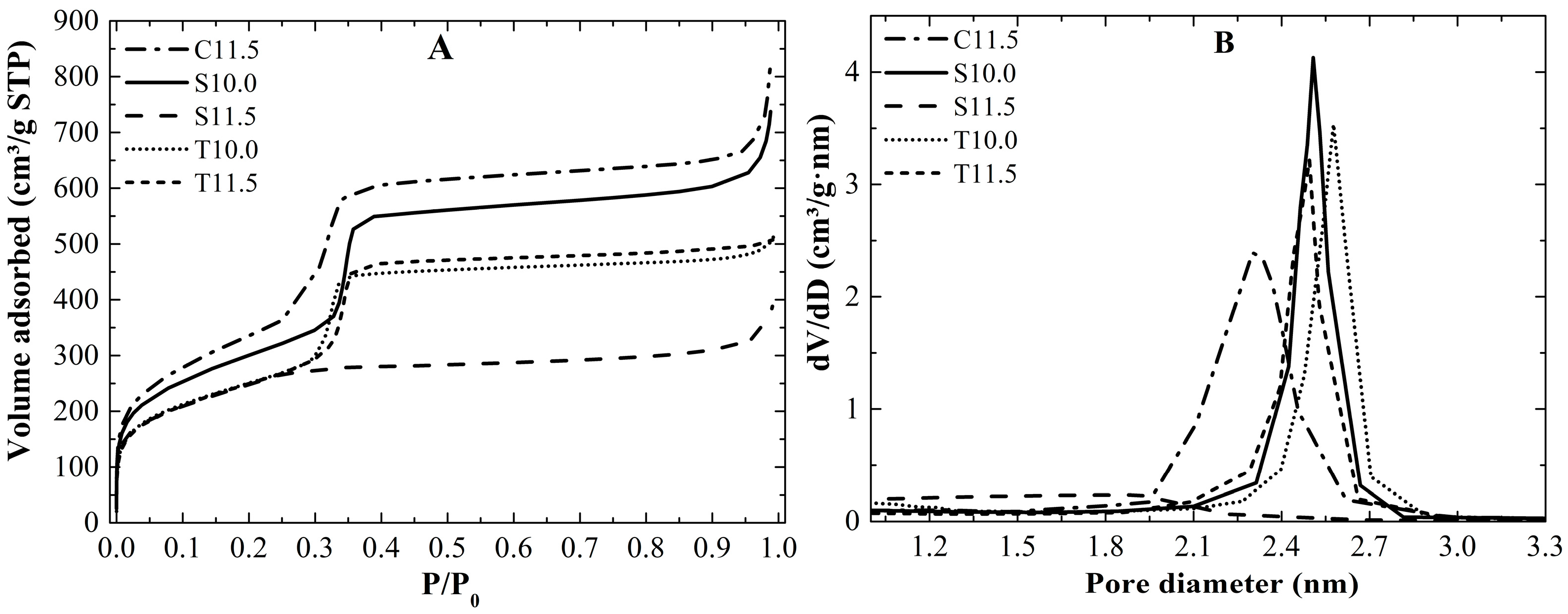
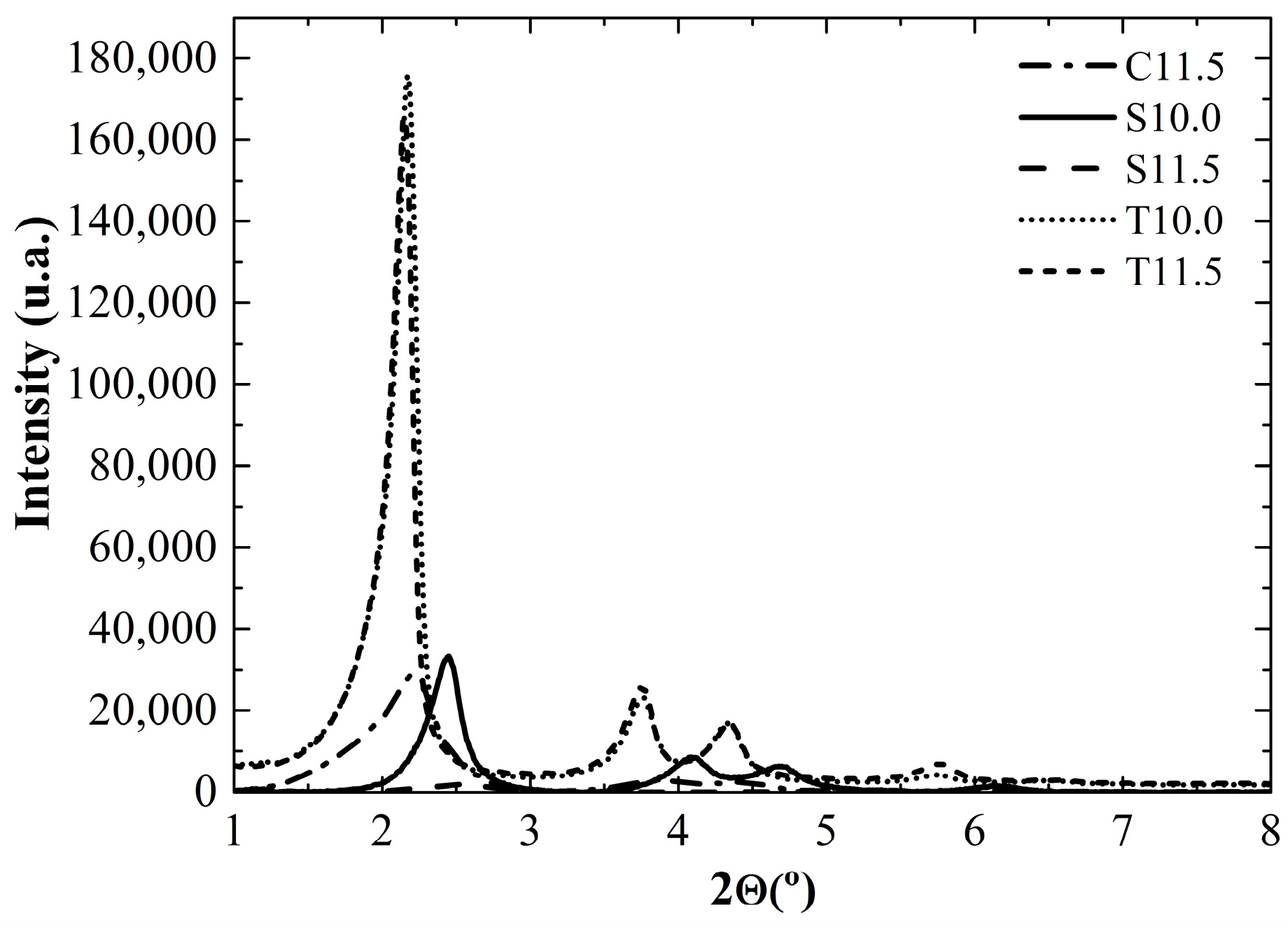
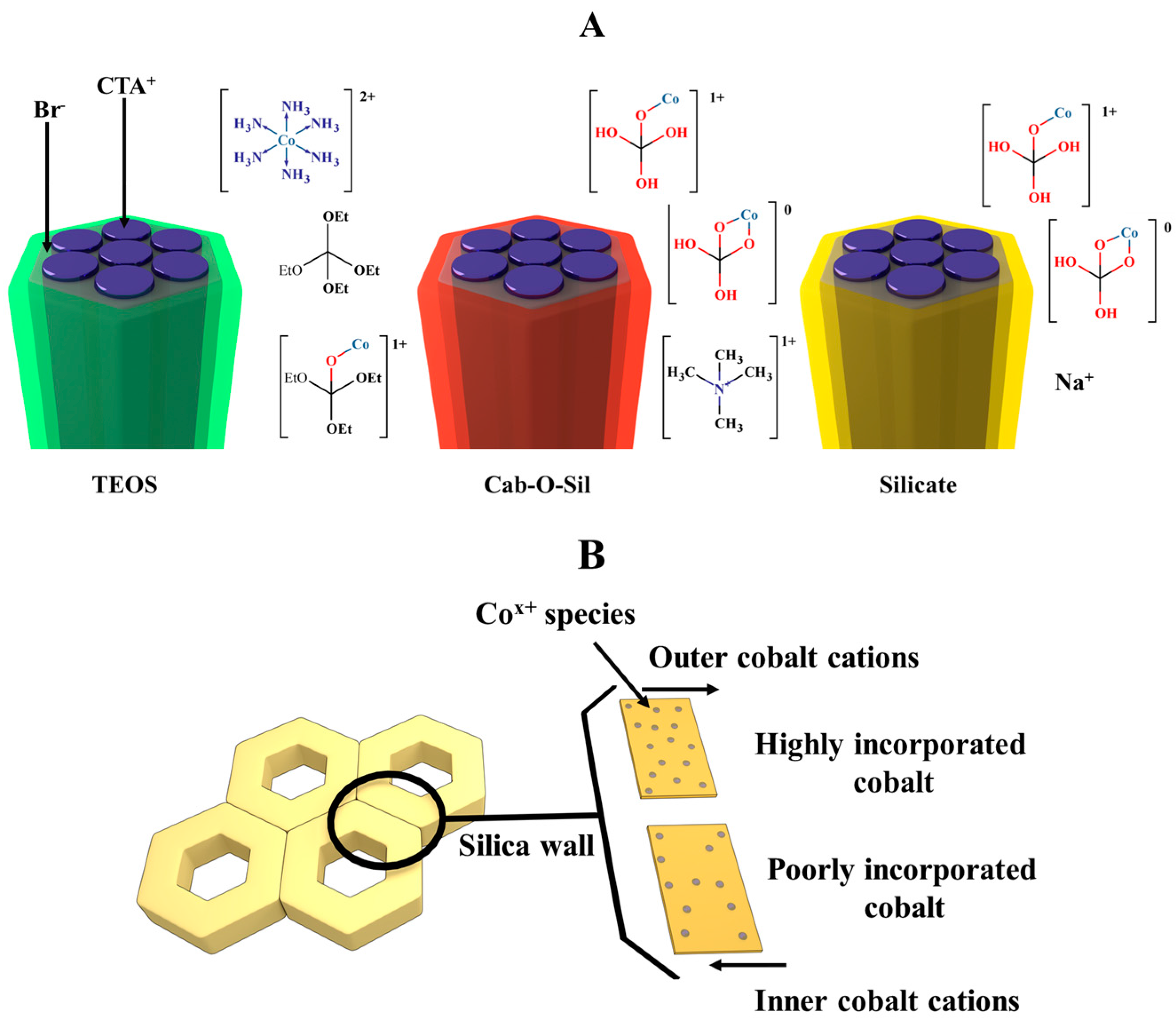
2.1. Silica Characterization

Figure 1 shows the adsorption isotherms of the silica synthesized starting at pH 10.0 and 11.5 with the different silica sources; all nitrogen adsorption profiles corresponded to type–IV isotherms according to the International Union of Pure and Applied Chemistry (IUPAC) assignation [1], that is, the materials had a narrow mesoporous pore size, except for the S11.5 sample.
The S11.5 did not show a capillary condensation step (P/P0 0.25–0.35); this suggests that the structure of this silica was not mesoporous, this behavior may be related to a low polycondensation degree conducting to an amorphous material after organic materials removal [22]. However, for the synthesis at pH 10.0, the mesostructure was highly ordered, as confirmed from the results summarized in Table 1, in which the slope of the capillary condensation step of S10.0 is the highest; the slope is directly related to the homogeneity of the porous structure. In contrast, the mesoporous silicas prepared with TEOS exhibited a narrow pore size distribution and large slope, with a larger slope for the synthesis at pH 11.5. However, the surface areas of C11.5 and S10.5 had the largest surface area, which is an important factor in designing mesoporous materials with high metal dispersion and thus the needed activity towards SWCNT [14].
Figure 2 shows the X-ray diffraction (XRD) patterns of mesoporous silica MCM-41. We can observe the characteristic reflections, (100), (110), and (200), and the higher in-plane reflection (210). This last reflection is only present in the highly ordered structures, such as the T10.0 and T11.5 samples. The intensity and the full width at maximum height (FWMH) are parameters that are directly related with the structural regularity. The higher the intensity is and the lower the FWMH is, the more ordered and homogeneous are the silica pore. According to the nitrogen adsorption and X-ray diffraction patterns, the prepared silicas T10.0 and T11.5 showed a higher structural order, while S10 was a poorly organized mesoporous silica and S11.5 showed a non-mesoporous structure.
Table 2 shows the cell parameters and wall thicknesses calculated for each MCM-41 sample. Although the pore diameter distributions were similar for all the mesoporous supports, there were significant differences in the wall thicknesses where C11.5 has the larger wall thickness. Larger wall thickness may confer a higher thermal stability of the siloxane network which may support high temperature processes; the colloidal silica Cab-O-Sil is an aggregate of nanometric particles that are hydrolyzed in the reaction medium, but the hydrolysis of the colloidal particles is not entirely complete resulting in minor-sized particles that exhibit slower polycondensation, and may contribute to a larger wall thickness and, hence, less organization. TEOS is an organic compound with low solubility in water, to hydrolyze the EtO-Si bond is necessary to have the species in solution thus the polycondensation when using TEOS may be the slowest among all silica sources leading to a porous structure construction more organized as the hydrolyzed species condense in a more organized fashion due to the lack of high amounts of silicate species in solution. As a matter of fact, the XRD patterns of the TEOS silicas show higher peak intensities and (200) and (210) reflections than the other supports. These findings are in agreement with the well-ordered structure of these supports.
d 100 = λ C u K α 2 s e n θ 100 a 0 = 2 d 100 3 ;   W t = a 0 D p

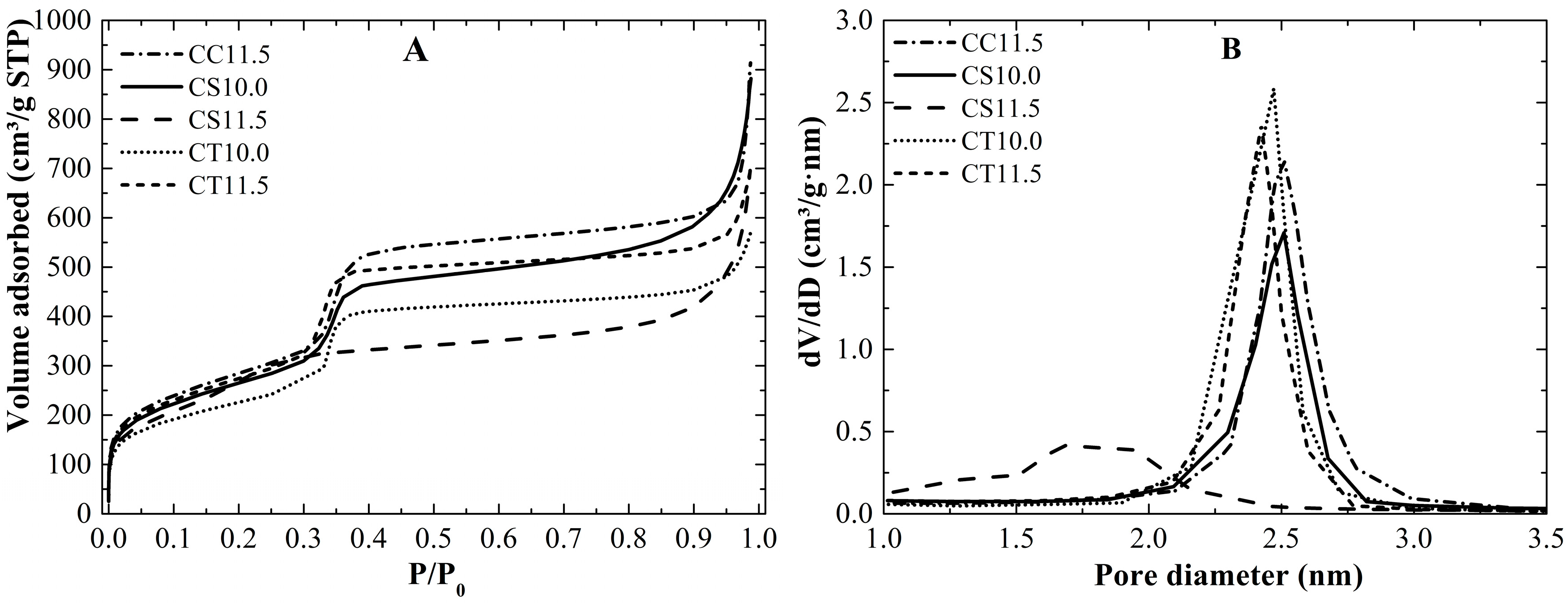
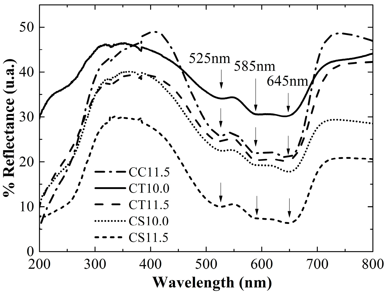
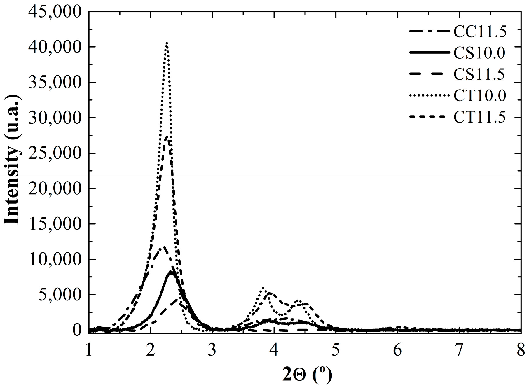
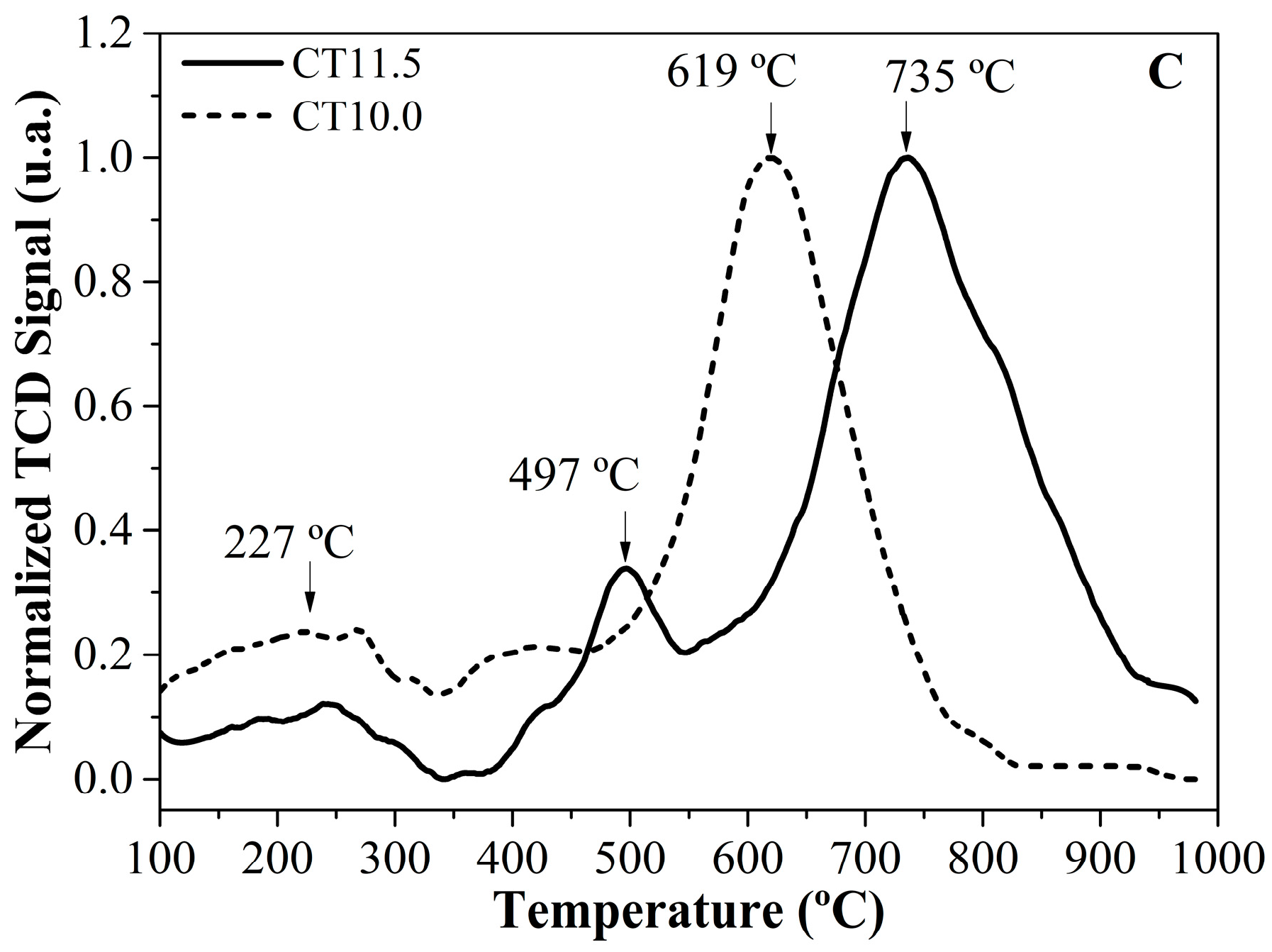
2.2. Catalysts Characterization

Figure 3A shows the nitrogen adsorption isotherms and Figure 3B shows the pore size distribution of each prepared catalyst, All the catalysts show type IV isotherms, except for CS11.5, which did not show an appreciable capillary condensation step, such as silica S11.5.
For the catalyst prepared with Cab-O-Sil (CC11.5) as the silica source, the nitrogen adsorption profile was nearly the same as that of silica, with a defined capillary step and a narrow pore size distribution. Nevertheless, the average pore size was different; the pore size of the catalyst was larger by approximately 0.2 nm, and the behavior can be explained considering the bond lengths of Si-O and Co-O: the latter is approximately 200 pm, while the first is 174 pm, therefore when one cobalt cation replaces one silicon atom the porous structure and size changes expanding the pore dimension. Ultimately, the catalyst has 215 m2g−1 less surface area than the support, and this result is in agreement with the inverse relationship between the pore size and the surface area [23].
The catalyst prepared using sodium silicate as the silica source and a pH of 10.0 (CS10.0) exhibited a lower superficial area and the same pore size distribution but with less intensity; these results indicate that the quantity of the pores was lower, and therefore, the surface area was lower as well. TEOS catalysts (CT10.0) and (CT11.5) exhibited a well-defined capillary condensation step, unlike the Cab-O-Sil catalyst, and the pore size distribution was nearly the same in both cases. Table 3 shows the real concentration of cobalt in the mesoporous supports, where catalysts CT10.0, CT11.5 and CC11.5 exhibit a larger actual cobalt concentration, possibly due to the slower polycondensation kinetics. When using TEOS as the silica source at pH 11.5 more cobalt was incorporated compared to the sample at pH 10.0 since at higher pH values, more TEOS hydrolyzed species are present. Hence, the cobalt cations were already interacting with the hydrolyzed TEOS prior to the polycondensation; therefore, once the polycondensation step began, the cobalt was incorporated more efficiently. Tetramethylammonium silicate and sodium silicate provided the hydrolyzed silicic acid, and the condensation of the in-solution silicate anions that interacted with the cobalt cations permitted larger incorporation. Nevertheless, sodium silicate at pH 10.0 did not show the same behavior as Cab-O-Sil. Since the difference between both processes is the soluble sililica source it is possible that sodium cations compete with cobalt cations to form SiO-Na bonds instead of SiO-Co, leading to a lower cobalt incorporation in the siloxane network.
Figure 4 shows the XRD patterns of all catalysts. For each catalyst only the diffraction peaks of the planes (100), (110), and (200) are visible except the CS11.5 catalyst which does not show the diffraction peaks characteristics of MCM-41 materials due to its amorphous nature. The peak that corresponds to the plane (210) reflection was not observed, which corroborates the fact that the incorporation of cobalt generated distortions in the mesoporous silica framework.
Table 3 shows the surface area and pore size distributions of both the silica and catalysts.
Figure 5 shows the diffuse reflectance UV-Vis (DRS–UV–Vis) spectra of the catalysts prepared using different silica sources. The spectra of all catalysts exhibited profiles that were consistent with absorption due to the 4A24T1(P) electronic transition of the d7 cobalt valence electrons when they occupied the tetrahedral holes in the silica wall, and the tripartition of the signal (525 nm, 585 nm, and 624 nm) was due to spin-orbit coupling. However, Torbjørn Vrålstad stated that ultraviolet spectroscopy is not sufficient for determining the state of cobalt in siloxane networks [24]. Hence, our results provide an estimation to corroborate the presence of tetrahedral cobalt but not the absence of octahedral cobalt. Cobalt with an octahedral symmetry occurs in CoO and a combination of distorted tetrahedral and octahedral environment in Co3O4; therefore, under this condition and given that all the ultraviolet profiles are nearly the same, we cannot discard the possibility of cobalt (II) and cobalt (II) oxides formation on the surface during catalyst synthesis. However, by means of a temperature programmed reduction (TPR) analysis it was possible to obtain indirect information about the cobalt species formed. Cobalt (II) oxide is reduced below 400 °C, while the cobalt silicate showed a higher reduction resistance, over 500 °C [25]
Figure 6 shows the temperature-programmed reduction profiles for each group of catalysts, i.e., sodium silicate, Cab-O-Sil and TEOS as the precursor. The TEOS-based catalysts show different profiles with the pH change. Figure 7A shows the cobalt cation interaction behavior prior to the polycondensation step and Figure 7B the cobalt cation incorporation degree. The maximum reduction temperature of CT11.5 was approximately 110 °C higher than that of CT10.0. This change is related to the Co incorporation level inside the silica wall. During the polycondensation process, the cobalt cations may be captured by hydrolyzed Si-OH species. Once the cation is captured, it might remain outside of the silica wall as surface cobalt oxide, or as sub-surface cobalt silicate species (shallow incorporation) or in the middle of the silica wall [26]. Inner cobalt cations are harder to reduce than sub-surface or outer cobalt cations because more energy is required for hydrogen molecules to diffuse through the silica wall to reach the cobalt cations. Therefore, at pH 11.5, the incorporated cobalt may be located deeper than the cobalt at pH 10.0. Upon the partial hydrolysis of TEOS, (EtO)3Si-O species are generated, once these species are produced they are able to catch cobalt cations from the solution. Since the equilibrium depends on the pH, higher pH values lead to higher content of charged silicate in the solution that forms SiO-Co resulting in a higher cobalt degree of incorporation and more uniformity in the cobalt cations distribution inside of the walls. Another feature found in the TPR profile of CT11.5 is a small signal located at 497 °C. This peak was attributed to the reduction of cobalt oxide species anchored to the MCM-41 wall through electrostatic interactions with the incorporated cobalt [27]. The sodium silicate-based catalysts (CS10.0 and CS11.5) exhibited nearly the same maximum reduction temperatures (771 and 776 °C), and the Co incorporation degree was higher at higher synthesis pH values. The CS11.5 presents a small broad peak below 400 °C which is most likely related to cobalt oxide, as the surface particles were physically attached to the support. The cobalt oxide was entirely reduced, leading to large cobalt clusters that did not have any selectivity toward SWCNT deposition [17]; therefore, poor or noncatalytic performance was expected. In contrast, the catalyst prepared with colloidal silica Cab-O-Sil as the precursor showed a maximum reduction temperature near 725 °C. This process was associated with the reduction of the cobalt silicate species produced during the polycondensation step. The reduction process occurred in a narrow range of temperatures, which was indicative of uniform Co incorporation throughout the entire support. After comparing the cobalt environments, Figure 7B, for the Cab-O-Sil (CC11.5) and sodium silicate (CS11.5)-based catalysts, we expected roughly the same incorporation degree. Both silicas sources were soluble in the reaction medium, and the cobalt cations preferably interacted with silicate species instead of bromide. When the polycondensation step occurred, cobalt cations that were bonded to the silicate became trapped in the siloxane network, leading to a greater extent of incorporation.
Among all catalysts analyzed here, CC11.5 had the lowest amount of surface cobalt oxide, demonstrating that Cab-O-Sil and tetramethylammonium silicate can incorporate cobalt more efficiently than the other catalysts analyzed in this study.

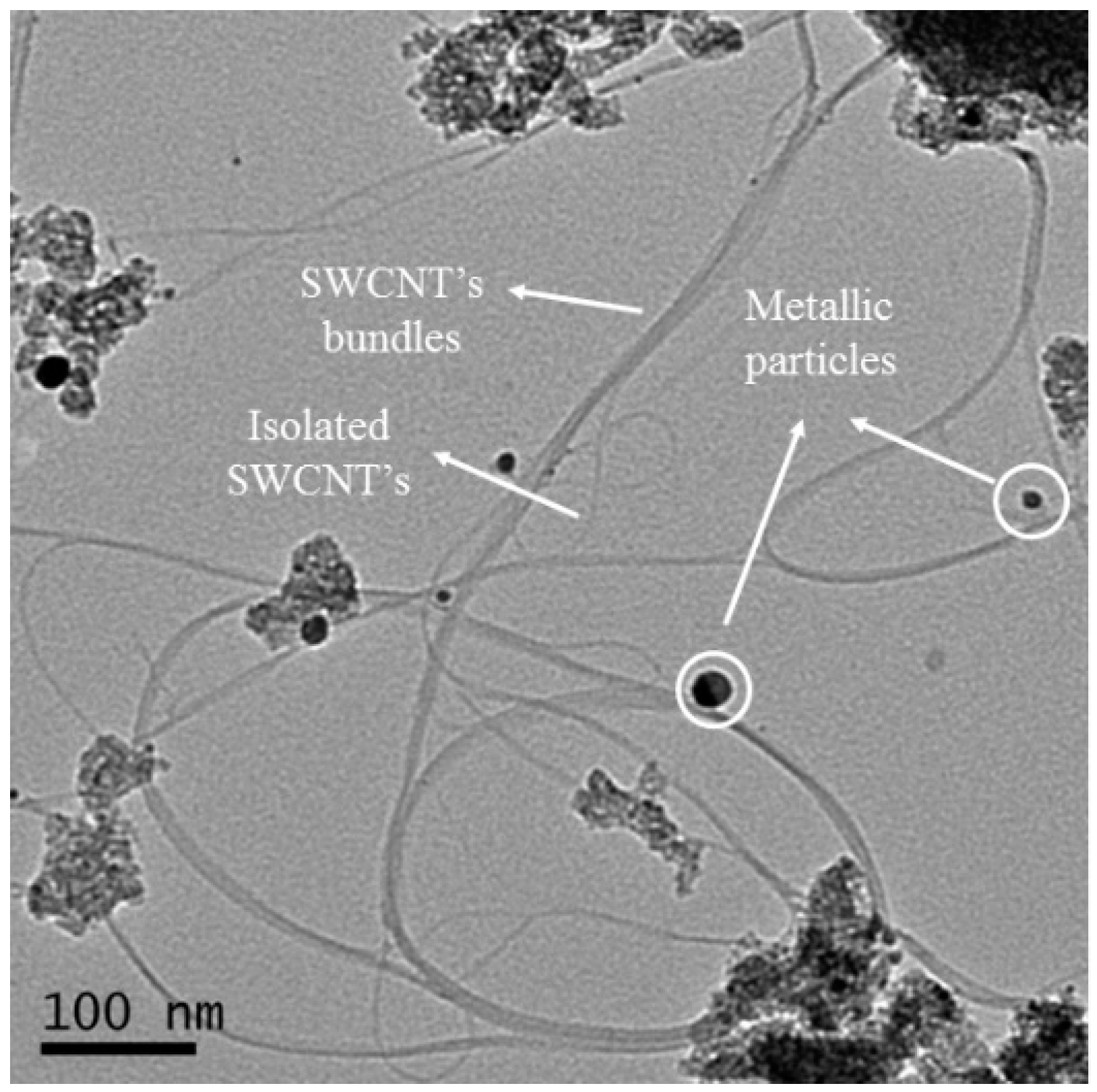
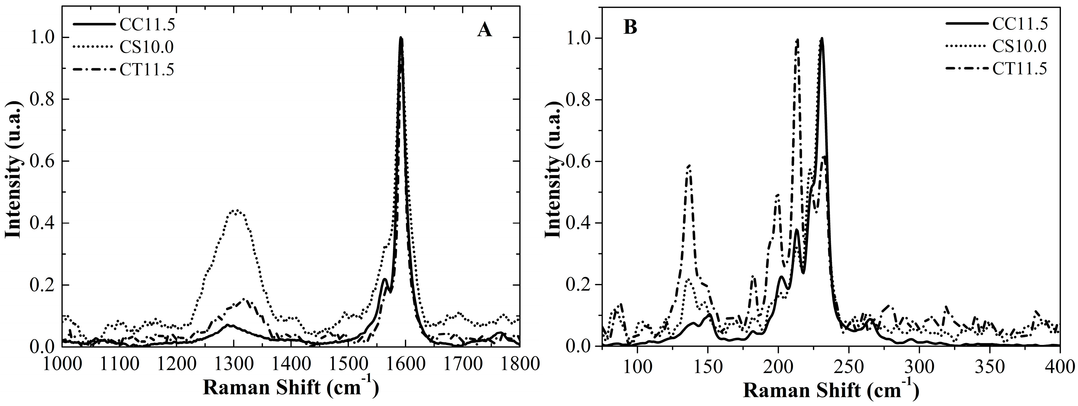
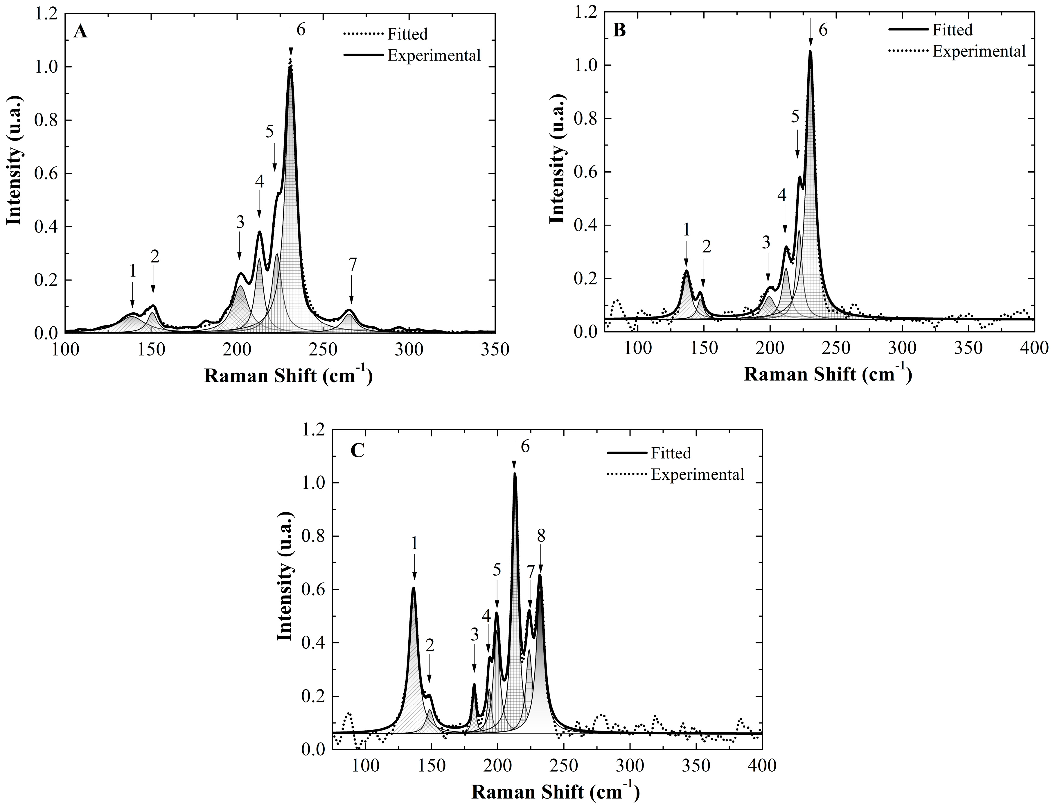
2.3. Catalyst Performance

The prepared catalysts were tested during the CCVD synthesis of SWCNT with methane as the carbon source under the same conditions: temperature, flow rate, and time. The bar diagram in Figure 8 depicts the total carbon yield. The highest carbon mass deposited was 3.5% for the CC11.5 catalyst after the reaction, while the carbon mass deposited by the other catalysts was not higher than 1.5%. According to the TPR results, each catalyst exhibited a different hydrogen-reduction profile. Among all the catalysts, CC11.5 showed the highest homogeneity in terms of the cobalt incorporation and one of the highest levels of cobalt content. The cobalt oxide and surface cobalt species exhibited low-temperature reduction behavior, and they were reduced earlier than the incorporated cobalt. As mentioned before, when this cobalt species was reduced, the large cobalt clusters lost their selectivity towards SWCNT. However, in the case of CC11.5, the catalyst did not show evidence of cobalt oxide. Therefore, CC11.5 presented the highest catalytic activity. Cobalt-incorporated MCM-41 using sodium silicate as the silica source was only active when the synthesis pH was 10.0, and a mesostructured catalyst was confirmed. CS11.5 showed a significant amount of cobalt oxide and did not exhibit a mesostructure or a high cobalt content according to TPR and N2-adsorption. This catalyst did not show any catalytic activity toward the SWCNT because the sintering process could not be controlled to avoid large particle sizes in the absence of mesoporosity to confine the cobalt clusters formed during the reduction step [7]. The CT10.0 and TEOS catalysts showed a low activity during SWCNT deposition. This behavior was attributed to the fact that the prereduction temperature was higher than the maximum reduction temperature. According to the TPR results, a large amount of reduced cobalt silicates formed during the prereduction process, leading to large particle sizes. Therefore, the activity was lost. CT11.5 had a higher reduction temperature than CT10.0. Hence, large particle sizes could be avoided during the prereduction process, leaving some cobalt inside of the silica framework to anchor the formed cobalt clusters and leading to a higher activity toward the SWCNT.
Figure 9 shows the Raman spectra of all carbon deposition over the catalysts without further purification. The Raman spectrum of the carbon nanotubes consists of three main bands. The G band at approximately 1580 cm−1 was attributed to the tangential vibration mode of benzene, such as the fused rings in the graphite sheet, and was directly related to the structural order in the carbon nanotubes. The D band appeared when there was partial or total destruction of the symmetry of benzene, such as fused rings, i.e., structural defects or the presence of amorphous carbon. This band is located at approximately 1350 cm−1. Finally, the most important band was the radial breathing mode (RBM) that is characteristic of SWCNT and is related to the SWCNT diameter. In addition, the wavelength of the apparition is inversely proportional to the diameter of the SWCNT. Thus, it is possible to determine the diameter distribution using a simple equation [28].
ω R B M = 234 ( cm 1   nm ) d t + 10   cm 1     Bundle   of   SWCNT
The ratio of intensity G/D is an important parameter that indicates the structural quality of graphitic materials, such as SWCNT. The higher the ratio of G/D, the higher is the structural order in the graphitic structure.
Only the carbon deposition over the CC11.5, CS11.5, and CT10.0 catalysts, which exhibited the highest content of carbon, were analyzed since the other catalysts did not show good Raman spectra Figure 9A shows the G and D bands. Notably, the carbon deposition over the CC11.5 catalyst showed a lower D band intensity and higher G band intensity; therefore, it presented the highest structural order among the other catalysts. In contrast, we found that catalyst CS10.0 also showed an intense D band, even though it showed a prominent G band. Then, the SWCNT produced with this catalyst exhibited larger structural disorder. It has been proven that the presence of sodium in Co-MCM-41 destroys its selectivity toward SWCNT deposition [25]. Finally, the CT11.5 catalyst also showed a prominent G band; however, there was a significant loss in the structural order as well. An examination of the radial breathing mode (RBM) zone, in Figure 9B, allows us to confirm the presence of SWCNT. The signals of the CC11.5 catalyst range from 175 cm−1 to 275 cm−1, while the other catalysts show distributions below 150 cm−1. The lower energy vibrations in the RBM zone are related to large-diameter SWCNT, even double-wall carbon nanotubes. Thus, CC11.5 has the highest activity and the narrowest diameter distribution.
A more detailed analysis of the RBM zone was made by converting the maximum intensity peak decomposition into Gaussian-like functions to estimate the SWCNT diameter distribution. Figure 10 shows the deconvolution of all spectra, and Table 4 summarizes the approximate populations calculated using the total area of the peaks within the radial breathing mode zone and each peak associated with each diameter of the SWCNT. From the obtained results, the SWCNT growth over the CC11.5 catalyst showed a high selectivity towards SWCNT with a diameter of 1.1 nm, as calculated with the previous equation. Approximately 60% of the diameters of the total SWCNT produced were close to 1.1 nm. Notably, approximately 89% of the total of SWCNT was within 0.9 nm and 1.1 nm, while 11% was within the diameter range between 1.7 nm and 1.8 nm. The CS10.0 catalyst showed a more disperse SWCNT diameter distribution than the SWNCTs deposited over the CC11.5 catalyst. In addition, the Raman spectrum did not show signals for SWCNT with diameters less than 1 nm, while that for the SWCNT grown over the CC11.5 catalyst did. The CT11.5 catalyst, unlike the other catalyst, showed even less uniformity in the diameter distribution; approximately 22% of the contribution of the SWCNT had diameters larger than 1.9 nm. The RBM deconvolution for CT11.5 deposition presented nonselectivity toward a narrow SWCNT diameter distribution. In summary, the CT11.5 catalyst is a proper material for growing SWCNT with a narrow diameter distribution with a selectivity toward diameters near 1.1 nm, which is a really close diameter for CCVD produced SWCNT.
Since a higher selectivity and yield of the CC11.5 catalyst was observed over the CT11.5 and CS10.0 toward SWCNT synthesis during the chemical vapor deposition of methane, it was chosen for transmission electron microscopy (TEM) analysis without purification. Figure 11 shows the TEM image of the obtained SWCNT. Clearly, multiwall carbon nanotubes, as structures with large diameters, can not be seen. The sample consisted of a few isolated SWCNT, but most of the sample showed bundles of SWCNT.

3. Materials and Methods

3.1. Co-MCM-41 Synthesis Using Colloidal Silica Cab-O-Sil as the Precursor (CC11.5)

The synthesis of the Co-MCM-41 catalyst was carried out by following the procedure described by Lim Sangyun et al. [29]. First, 2.50 g of colloidal silica Cab-O-Sil (99.5%) Sigma-Aldrich (St. Louis, MO, USA) and 10 mL of tetramethylammonium silicate Sigma-Aldrich (St. Louis, MO, USA) (15–20%) (TMASiO2) were stirred for 30 min in 50 mL of deionized water; then, the proper amount of the cobalt precursor [Co.(NO3)2.6H2O] Merck (Kenilworth, NJ, USA) (99.3%) was added to reach a 3% nominal mass of cobalt. The mixture was kept under constant stirring for 30 min, and then, two drops of antifoam A Sigma-Aldrich (St. Louis, MO, USA) and 28.79 g of cetyltrimethylammonium hydroxide (CTMAOH) were added. Next, the pH was adjusted to 11.5 using glacial acetic acid Merck (Kenilworth, NJ, USA) (99%). The CTMAOH was previously prepared using 20% cetyltrimethylammonium bromide Sigma-Aldrich (St. Louis, MO, USA) (CTMABr, 99%) and an ionic exchange resin, Ambersep 900® Sigma-Aldrich (St. Louis, MO, USA), in the proportion of 1 mmol CTMABr: 1 mL Ambersep 900®. Previous works have shown that both MCM-41 [20] and the Co-MCM-41 catalyst [30] have good thermal stability and pore uniformity when the synthesis is conducted under these conditions.

3.2. Co-MCM-41 Synthesis Using Sodium Silicate as the Precursor

Catalysts prepared using sodium silicate as silica source are named as CSX where C is for catalyst, S for silicate, and X is the synthesis pH. Co-MCM-41 catalyst synthesized at pH 10.0 (CS10.0) MCM-41 synthesized at pH 11.5 (CS11.5).
The synthesis of the catalysts using sodium silicate as the silica precursor was carried out by following the procedure described by Giraldo et al. [18]. First, 2.00 g of CTMABr was dissolved in 10 mL of 0.1 M HCl (Merck), then the proper amount of the cobalt precursor was added to reach a 3% nominal mass of cobalt in the silica support. Next, 6.00 g of a sodium silicate solution Sigma-Aldrich (St. Louis, MO, USA), (25.5–28.5% SiO2), previously dissolved in 30 mL of deionized water, was added and, the reaction was left under stirring for 30 min. Finally, the pH in the sol–gel process was adjusted to 10 and 11.5. This synthesis has the advantage of requiring a less expensive silica source.

3.3. Co-MCM-41 Synthesis Using TEOS as the Precursor

Catalysts prepared using TEOS as silica source are named as CTX where C is for catalyst, T for TEOS and X is the synthesis pH. Co-MCM-41 catalyst synthesized at pH 10.0 (CT10.0) MCM-41 synthesized at pH 11.5 (CT11.5)
The synthesis of catalysts using TEOS as the silica precursor was carried out following the procedure described by M. Grün, K. et al. [23]. First, 2.00 g of CTMABr were added in 50 mL of deionized water and maintained under magnetic stirring until reaching complete dissolution. The proper amount of the cobalt precursor [Co.(NO3)2.6H2O] to reach a 3% nominal mass of cobalt in the silica support was added to this solution, and then 8 mL ammonia (27% w/v) was incorporated. The mixture was left under magnetic stirring for 30 min. Then, 5.00 g of tetraethylortho silciate (TEOS) Sigma-Aldrich (St. Louis, MO, USA) (99%) was added dropwise to this solution, and the pH was adjusted to 10.0 (CT10.0) and 11.5 (CT11.5)
All syntheses were subjected to hydrothermal treatment in an autoclave for three days at 100 °C to promote silica polycondensation into siloxane networks around the surfactant aggregates. Once the hydrothermal treatment was completed, the obtained materials were calcined at 540 °C under air atmosphere.

3.4. MCM-41 Silica Synthesis

The mesoporous MCM-41 silica was synthesized following the procedures described above, except for the cobalt incorporation step, using the following silica precursors: sodium silicate, Cab-O-Sil and TEOS, MCM-41 sample names use similar acronyms as catalyst, XY, where X is C for Cab-O-Sil, T for TEOS and S for silicate and Y is for synthesis pH, thus, C11.5 is for MCM-41 Cab-O-Sil synthesized at pH 11.5, S10.0, and S11.5 for sodium silicate MCM-41 synthesized at pH 10.0 and 11.5 respectively, T10.0 and T11.5 for TEOS MCM-41 synthesized at pH 10.0 and 11.5 respectively.

3.5. Catalytic Performance Evaluation

Each catalyst was tested during the CCVD of methane to produce SWCNT. First, 200 mg of the catalyst was set into a 20 mm diameter circle on a fritted quartz disk inside of a 50 cm diameter quartz tube and placed into a vertical oven that was heated to 700 °C under a nitrogen flow rate of 50 cm3min−1 at 20 °C min−1. Then the nitrogen flux was replaced with a mixture of 150 cm3min−1: 50 cm3min−1 N2:H2 as a reducing agent for 30 min. Once the reduction was completed, the oven was rapidly heated to 800 °C under nitrogen flux; then, a mixture of 150 cm3min−1: 50 cm3min−1 CH4:N2 was used as a carbon source. The carbon deposition was carried out for a 30 min period, and finally, the methane and nitrogen mixture was switched to pure nitrogen. The oven was left to cool, and the blackish product was collected and characterized without any further purification.

3.6. Characterization of the Co-MCM-41 Catalysts

Nitrogen physisorption on MCM-41 and Co-MCM-41 was carried using a Micromeritics Accelerated Surface Area and Porosimetry System (ASAP) 2010 (Norcross, GA, USA) at the nitrogen normal boiling point (77K) to evaluate their adsorption–desorption isotherms, total surface area, and pore size distributions. Diffuse reflectance ultraviolet–visible spectroscopy (DRS–UVVis) measurements were conducted using a Perkin–Elmer Lambda 35 (‎Waltham, MA, USA) to determine the presence of cobalt in the catalysts [31]. Temperature programmed reduction (TPR) data were collected to examine the cobalt cation incorporation degree within the silica structures [26] using a Micromeritics AutoChem II 2920 (Norcross, GA, USA) chemisorption analyzer equipped with a thermal conductivity detector (TCD) using 50 mg of a degassed catalyst at 250 °C under 5% H2/Ar at a heat rate of 5 °C/min from atmosphere temperature to 1000 °C. The temperature was maintained for one hour to ensure total cobalt (II) and cobalt (III) reduction. The, catalysts and silica mesostructures were evaluated with X–ray diffraction measurements using a Siemens (Berlin, Germany) D5000 Cu–Kα (λα = 1.54 Å scanning 2θ from 0.7° to 10° step size 0.048°), and finally, the total cobalt amount was quantified by atomic absorption spectroscopy (AAS) Thermo Fisher Scientific (Waltham, MA, USA) Unicam 929 using a cobalt lamp and a cobalt (II) calibration curve from 1–5 mg/mL.

3.7. CCVD Deposited Products Characterization

The amount of carbon deposition was measured using the TGA technique with a TA Instruments (New Castle, DE, USA) thermogravimetric analyzer (Q500) that was heated at 10 °Cmin−1 from room temperature to 800 °C under an oxidant atmosphere. The structural quality of the SWCNT was investigated with Raman microscopy measurements using a Horiba (Kyoto, Kyoto Prefecture, Japan) Labram HR with a 732 nm excitation wavelength, spectral deconvolution was performed using Originlab with Lorentzian functions to determine the intensity maximum of each peak and area for population analysis. Transmission electron micrographs were collected with a Thermo Fisher Scientific (Waltham, MA, USA) Tecnai F20 200 KV, and the carbon deposition was characterized without any purification procedure.

4. Conclusions

In this work, we determined that Co. catalysts prepared with colloidal silica Cab-O-Si MCM-41 exhibit better cobalt incorporation capabilities within the siloxane network without significant loss in mesoporosity or the physical integrity of the support compared with the catalysts prepared using sodium silicate and TEOS as precursors under the same conditions. In addition, cobalt was successfully incorporated without forming cobalt oxide on the silica walls. When the catalytical properties were evaluated during SWCNT preparation, the CC11.5 catalyst exhibited the best performance and produced graphite-like materials with high structural regularity and the highest yield among all catalysts tested in this study. Moreover, the SWCNT growth on the CC11.5 catalyst showed a narrower diameter distribution among all the deposited materials on the several catalysts. From the TEM analysis, neither amorphous carbon nor multiwall carbon nanotubes were formed. In general, from this work, we can conclude that the Co-MCM-41 catalyst prepared using colloidal silica Cab-O-Sil as the precursor and methane as the carbon source is an economic alternative for producing SWCNT with good structural regularity. Nevertheless, the CO disproportion SWCNT synthesis offers higher yield (higher than 3.0% here attained) and therefore optimization of the methane CCVD synthesis over Cab-O-Sil based catalyst could be improved to reach higher yields.

Acknowledgments

Frank Ramírez Rodríguez thanks Colciencias Colombia for the program “Francisco José de Caldas Convocatoria Nacional para Estudios de Doctorado en Colombia” N° 511. The authors declare no conflict of interest.

Author Contributions

Luis Fernando Giraldo and Frank Ramírez Rodríguez designed the experiments; Frank Ramírez Rodríguez performed the experiments and data analysis; Luis Fernando Giraldo, Betty Lucy López and Frank Ramírez Rodríguez wrote the manuscript.

Conflicts of Interest

The authors declare no conflict of interest.

References

  1. Donohue, M.; Aranovich, G. Classification of Gibbs adsorption isotherms. Adv. Colloid Interface Sci. 1998, 76–77, 137–152. [Google Scholar] [CrossRef]
  2. Liu, Z.; Zhou, J.; Cao, K.; Yang, W.; Gao, H.; Wang, Y.; Li, H. Highly dispersed nickel loaded on mesoporous silica: One-spot synthesis strategy and high performance as catalysts for methane reforming with carbon dioxide. Appl. Catal. B Environ. 2012, 125, 324–330. [Google Scholar] [CrossRef]
  3. Iwamoto, M.; Kosugi, Y. Highly Selective Conversion of Ethene to Propene and Butenes on Nickel Ion-Loaded Mesoporous Silica Catalysts Highly Selective Conversion of Ethene to Propene and Butenes on Nickel Ion-Loaded Mesoporous Silica Catalysts. Society 2007, 13–15. [Google Scholar] [CrossRef]
  4. Guidotti, M.; Pirovano, C.; Ravasio, N.; Lázaro, B.; Fraile, J.M.; Mayoral, J.A.; Coq, B.; Galarneau, A.; Lazaro, B.; Fraile, J.M.; Mayoral, J.A.; et al. The use of H2O2 over titanium-grafted mesoporous silica catalysts: A step further towards sustainable epoxidation. Green Chem. 2009, 11, 1421. [Google Scholar] [CrossRef]
  5. Pal, N.; Bhaumik, A. Soft templating strategies for the synthesis of mesoporous materials: Inorganic, organic-inorganic hybrid and purely organic solids. Adv. Colloid Interface Sci. 2013, 189–190, 21–41. [Google Scholar] [CrossRef] [PubMed]
  6. Katok, K.V.; Tertykh, V.A.; Brichka, S.Y.; Prikhod’ko, G.P. Pyrolytic synthesis of carbon nanostructures on Ni, Co, Fe/MCM-41 catalysts. Mater. Chem. Phys. 2006, 96, 396–401. [Google Scholar] [CrossRef]
  7. Chen, Y.; Ciuparu, D.; Yang, Y.; Lim, S.; Wang, C.; Haller, G.L.; Pfefferle, L.D. Single-wall carbon nanotube synthesis by CO disproportionation on nickel-incorporated MCM-41. Nanotechnology 2005, 16, S476. [Google Scholar] [CrossRef] [PubMed]
  8. Chai, S.-P.; Zein, S.H.S.; Mohamed, A.R. Preparation of carbon nanotubes over cobalt-containing catalysts via catalytic decomposition of methane. Diam. Relat. Mater. 2007, 16, 1656–1664. [Google Scholar] [CrossRef]
  9. Pfefferle, L.; Haller, G.; Chen, Y.; Ciuparu, D.; Lim, S.; Yang, Y.H. Mechanism study on cobalt cluster size control in Co-MCM-41 during single wall carbon nanotubes synthesis by Co disproportionation. Abstr. Pap. Am. Chem. Soc. 2005, 229, 15565–15571. [Google Scholar] [CrossRef]
  10. Zoican Loebick, C.; Abanulo, D.; Majewska, M.; Haller, G.L.; Pfefferle, L.D. Effect of reaction temperature in the selective synthesis of single wall carbon nanotubes (SWNT) on a bimetallic CoCr-MCM-41 catalyst. Appl. Catal. A Gen. 2010, 374, 213–220. [Google Scholar] [CrossRef]
  11. Mizokawa, T.; Tjeng, L.H.; Steeneken, P.G.; Brookes, N.B.; Tsukada, I.; Yamamoto, T.; Uchinokura, K.; Burnus, T.; Hu, Z.; Hsieh, H.H.; et al. Relationship between the Structure/Composition of Co–Mo Catalysts and Their Ability to Produce Single-Walled Carbon Nanotubes by CO Disproportionation. Phys. Rev. B 2001, 108, 16201–16207. [Google Scholar] [CrossRef]
  12. Couteau, E.; Hernadi, K.; Seo, J.W.; Thiên-Nga, L.; Mikó, C.; Gaál, R.; Forró, L. CVD synthesis of high-purity multiwalled carbon nanotubes using CaCO3 catalyst support for large-scale production. Chem. Phys. Lett. 2003, 378, 9–17. [Google Scholar] [CrossRef]
  13. Li, W.; Bai, Y.; Zhang, Y.; Sun, M.; Cheng, R.; Xu, X.; Chen, Y.; Mo, Y. Effect of hydroxyl radical on the structure of multi-walled carbon nanotubes. Synth. Met. 2005, 155, 509–515. [Google Scholar] [CrossRef]
  14. Panpranot, J.; Kaewkun, S.; Praserthdam, P.; Goodwin, J.G. Effect of cobalt precursors on the dispersion of cobalt on MCM-41. Catal. Lett. 2003, 91, 95–102. [Google Scholar] [CrossRef]
  15. Peigney, A.; Coquay, P.; Flahaut, E.; Vandenberghe, R.E.; De Grave, E.; Laurent, C. A Study of the Formation of Single- and Double-Walled Carbon Nanotubes by a CVD Method. J. Phys. Chem. B 2001, 105, 9699–9710. [Google Scholar] [CrossRef] [Green Version]
  16. Ciuparu, D.; Chen, Y.; Lim, S.; Haller, G.L.; Pfefferle, L. Uniform-diameter single-walled carbon nanotubes catalytically grown in cobalt-incorporated MCM-41. J. Phys. Chem. B 2004, 108, 503–507. [Google Scholar] [CrossRef]
  17. Chen, Y.; Ciuparu, D.; Lim, S.; Yang, Y.; Haller, G.L.; Pfefferle, L. Synthesis of uniform diameter single-wall carbon nanotubes in Co-MCM-41: Effects of the catalyst prereduction and nanotube growth temperatures. J. Catal. 2004, 225, 453–465. [Google Scholar] [CrossRef]
  18. Giraldo, L.F.; Echeverri, M.; López, B.L. Reinforcement of polyamide 6 with nanoparticles. Macromol. Symp. 2007, 258, 119–128. [Google Scholar] [CrossRef]
  19. Kruk, M.; Jaroniec, M.; Sakamoto, Y.; Terasaki, O.; Ryoo, R.; Ko, C.H. Determination of Pore Size and Pore Wall Structure of MCM-41 by Using Nitrogen Adsorption, Transmission Electron Microscopy, and X-ray Diffraction. J. Phys. Chem. B 2000, 104, 292–301. [Google Scholar] [CrossRef]
  20. Amama, P.B.; Lim, S.; Ciuparu, D.; Pfefferle, L.; Haller, G.L. Hydrothermal synthesis of MCM-41 using different ratios of colloidal and soluble silica. Microporous Mesoporous Mater. 2005, 81, 191–200. [Google Scholar] [CrossRef]
  21. Ghampson, I.T.; Newman, C.; Kong, L.; Pier, E.; Hurley, K.D.; Pollock, R.A.; Walsh, B.R.; Goundie, B.; Wright, J.; Wheeler, M.C.; et al. Effects of pore diameter on particle size, phase, and turnover frequency in mesoporous silica supported cobalt Fischer–Tropsch catalysts. Appl. Catal. A Gen. 2010, 388, 57–67. [Google Scholar] [CrossRef]
  22. Voegtlin, A.C.; Matijasic, A.; Patarin, J.; Sauerland, C.; Grillet, Y.; Huve, L. Room-temperature synthesis of silicate mesoporous MCM-41-type materials: Influence of the synthesis pH on the porosity of the materials obtained. Microporous Mater. 1997, 10, 137–147. [Google Scholar] [CrossRef]
  23. Grün, M.; Unger, K.K.; Matsumoto, A.; Tsutsumi, K. Novel pathways for the preparation of mesoporous MCM-41 materials: Control of porosity and morphology. Microporous Mesoporous Mater. 1999, 27, 207–216. [Google Scholar] [CrossRef]
  24. Vrlstad, T.; Glomm, W.R.; Rønning, M.; Dathe, H.; Lercher, J.A.; Stcker, M.; Sjblom, J.; Vrålstad, T.; Sjo, J. Spectroscopic Characterization of Cobalt-Containing Mesoporous Materials Spectroscopic Characterization of Cobalt-Containing Mesoporous Materials. J. Phys. Chem. B 2006, 4, 5386–5394. [Google Scholar] [CrossRef] [PubMed]
  25. Herrera, J.E.; Resasco, D.E. Loss of single-walled carbon nanotubes selectivity by disruption of the Co-Mo interaction in the catalyst. J. Catal. 2004, 221, 354–364. [Google Scholar] [CrossRef]
  26. Lim, S.; Yang, Y.; Ciuparu, D.; Wang, C.; Chen, Y.; Pfefferle, L.; Haller, G.L. The effect of synthesis solution pH on the physicochemical properties of Co substituted MCM-41. Top. Catal. 2005, 34, 31–40. [Google Scholar] [CrossRef]
  27. Lim, S.; Wang, C.; Yang, Y.; Ciuparu, D.; Pfefferle, L.; Haller, G.L. Evidence for anchoring and partial occlusion of metallic clusters on the pore walls of MCM-41 and effect on the stability of the metallic clusters. Catal. Today 2007, 123, 122–132. [Google Scholar] [CrossRef]
  28. Belin, T.; Epron, F. Characterization methods of carbon nanotubes: A review. Mater. Sci. Eng. B Solid-State Mater. Adv. Technol. 2005, 119, 105–118. [Google Scholar] [CrossRef]
  29. Lim, S.; Ciuparu, D.; Pak, C.; Dobek, F.; Chen, Y.; Harding, D.; Pfefferle, L.; Haller, G. Synthesis and Characterization of Highly Ordered Co−MCM-41 for Production of Aligned Single Walled Carbon Nanotubes (SWNT). J. Phys. Chem. B 2003, 107, 11048–11056. [Google Scholar] [CrossRef]
  30. Lim, S.; Ciuparu, D.; Yang, Y.; Du, G.; Pfefferle, L.D.; Haller, G.L. Improved synthesis of highly ordered Co-MCM-41. Microporous Mesoporous Mater. 2007, 101, 200–206. [Google Scholar] [CrossRef]
  31. Lim, S.; Ciupani, D.; Chen, Y.; Pfefferle, L.; Haller, G.L. Effect of Co-MCM-41 conversion to cobalt silicate for catalytic growth of single wall carbon nanotubes. J. Phys. Chem. B 2004, 108, 20095–20101. [Google Scholar] [CrossRef]
Figure 1. (A) N2 adsorption isotherms of the silica supports; (B) Barrett-Joyner-Halenda (BJH) pore size distributions.
Carbon 04 00016 g001
Figure 2. X-ray diffraction (XRD) patterns of the silica supports.
Carbon 04 00016 g002
Figure 3. (A) Nitrogen adsorption isotherms. (B) BJH pore size distribution of the catalysts.
Carbon 04 00016 g003
Figure 4. XRD patterns of the catalysts.
Carbon 04 00016 g004
Figure 5. Diffuse reflectance UV-Vis spectra of the catalysts.
Carbon 04 00016 g005
Figure 6. Temperature programmed reduction (TPR) profiles of the Co-MCM-41 catalysts using (A) Cab-O-Sil (B) sodium silicate, and (C) tetraethylorthosilicate (TEOS) as precursors.
Carbon 04 00016 g006aCarbon 04 00016 g006b
Figure 7. (A) Cobalt cation interaction behavior prior to the polycondensation step. (B) Cobalt cation incorporation degree.
Carbon 04 00016 g007
Figure 8. Total carbon deposited over the catalysts.
Carbon 04 00016 g008
Figure 9. Raman spectra of the carbon depositions over the Co-MCM-41 catalysts: (A) D and G bands, (B) radial breathing mode zone.
Carbon 04 00016 g009
Figure 10. Radial breathing mode (RBM) deconvoluted spectra of the total deposited single-wall carbon nanotubes (SWCNT); (A): CC11.5, (B): CS10.0, and (C): CT11.5 catalysts.
Carbon 04 00016 g010
Figure 11. Transmission electron microscopy (TEM) images of the SWCNT growth on the CC11.5 catalyst.
Carbon 04 00016 g011
Table 1. Nitrogen physisorption results. FWHM: full width at maximum height.
SilicaSA (m2g−1)Dp (nm)DP FWMH (nm)
C11.51239.62.30.48
S10.01080.22.50.25
T10.0902.32.60.16
T11.5899.62.50.16
Table 2. Pore diameters, Bragg’s parameters, and wall thicknesses of the silica supports.
SilicaDp (nm)FWMH (nm)2Θ (°)d100 (nm)a0 (nm)Wt (nm)
C11.52.30.482.223.974.582.3
S10.02.510.252.453.64.161.7
T10.02.580.162.174.064.692.1
T11.52.490.162.154.104.742.2
Table 3. Surface area and pore size distributions of both the silica and catalysts.
CatalystCatalyst SA (m2g−1)∆SA (m2g−1)Silica Dp (nm)Catalyst Dp (nm)Co (%) #
CC11.51024.4215.22.292.512.02
CS10.0957.1123.12.492.461.66
CS11.5NANANANA1.90
CT10.0810.991.42.552.411.99
CT11.5990.2-90.62.452.392.18
# Final concentration of cobalt determined from atomic absorption data.
Table 4. Single-wall carbon nanotubes (SWCNT) diameters and populations.
Radial Breathing Mode (RBM) Peaks of the SWNCT Deposited on CC11.5
Peak NumberRaman Shift (cm−1)Tube Diameter (nm)Peak Area (cm−1. Intensity)Population (%)
1138.761.81.827.6
2150.671.70.823.4
3201.871.23.0612.8
4212.871.22.5310.6
5223.101.13.2213.4
6231.001.111.4547.7
7265.010.91.084.5
RBM peaks of the SWNCT deposited on CS10.0
Peak numberRaman shift (cm−1)Tube diameter (nm)Peak area (cm−1. Intensity)Population (%)
1136.861.82.109.9
2147.391.70.693.2
3199.391.21.487.0
4212.051.22.1410.0
5222.001.12.9613.9
6230.531.111.9056.0
RBM peaks of the SWNCT deposited on CT11.5
Peak numberRaman shift (cm−1)Tube diameter (nm)Peak area (cm−1. Intensity)Population (%)
1136.341.96.5922.2
2148.661.70.973.3
3182.191.40.762.6
4193.681.30.993.3
5199.241.23.5311.9
6213.131.28.1027.3
7223.751.12.9610.0
8232.001.15.7919.5

